Entryvue VD-950 User manual
- Category
- Door intercom systems
- Type
- User manual

Door Station A Door Station B Door Station C Door Station F Door Station G
The design and specications of this manual can be changed without notication
to the user. All copyrights and interpretation rights are reserved to Evervue.

1
2
ON
DPS
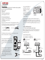
Basic instructions:
1. Check the contents of your order. To be able to set up a system,
you must have at least the following:
*One Door station
*One Monitor
*DPS Box (Power distributor Box)
*Power Supply (PS-50 or PS-55)
2. Recommended wires are:
*14 gauge 2 conductor stranded wire.
*CAT5 (MUST use a pair of wire for
each conductor)
Strip the ends of the wires about 1/3”. If using stranded wires or CAT5,
solder the ends to ensure a good connection. Do Not use wire nuts to
connect wires(wire nuts are for power and solids wires).
3. If multiple door stations and monitors are used, you can con nect
them in series (daisy chain) or in parallel.
4. Connect the wire to the BUS connection
on the Door Station ( 2 connections on the
left ). Then connect the other end of that
same wire to the left connectionon the DPS
box.
4.1 Connect the wire to the right side of
the DPS Box. Then connect the other
end of that same wire to the green plug
and then to the back of the monitor.
Make sure that these wires do not twist
too much, and that they are well isolated
from each other.
5. Door Strike/Magnetic lock
5.1 Door Lock controlled by Dry Contact:
If you have a large system, it is not recommended to have the Door
Station providing the power for the lock, so use a separate power
supply for the door lock.
The unlock setting on monitor:
8010 - lock mode to 0 - Normally open
8011 - lock mode to 1 - Normally closed
*Use Exit Bottom with magnetic lock only.
good
wrong
well twisted and soldered
Connect one lock
lock lock 1
lock 2
Remove jumper
Connect two locks
Remove jumper
*Exit Button
( Magnetic lock only )
*Exit Button
( Magnetic lock only )
Page 01
4.2. Connect the Red Wire of
the DPS Box to the Positive
(24V) of the power supply,
usually the
V+ or the Red connection. The
black wire should connect to the
V- or the black connection of
the power supply.
4.3. Plug in the power supply. Connect the terminal L and N to 110 -
240V input. This can be hardwired, or you can connect a cable w ith a
plug. If you have a PS-55, make sure that the voltage switch in the unit
is set to 110V or 220V before turning ON (depending the country you
live).

5.2 Door Lock controlled with Internal Power - Door strike:
Recommended only for 1 Door Station + 1 Monitor
-The door lock is limited to 12V, 250mA
-The Unlock Setting of monitor must be set to 0 (by default).
6. Ensure to set the Dip Switches of the Door Stations and Monitors
correctly. Refer to the next page.
7. Unlock Setting (set in monitor)
-You must connect the system correctly before programming the unlock
setting.
-It will be saved automatically, so you only need to set in one monitor.
1. Press the “EntryVue” logo located on the bottom left of the screen.
2. Press the screen for 3 seconds,then select “Installer’s Menu .”
3. Then enter one of the following codes:
8021# : 1 second
8022# : 2 seconds
8023# : 3 seconds
8024# : 4 seconds
8025# : 5 seconds
8026# : 6 seconds
8027# : 7 seconds
8028# : 8 seconds
8029# : 9 seconds
8.Innercall Feature;
There are 2 ways to set up the intercom function, and you need to decide
which one you want during the set up.
1. You can call a specic monitor. This is the standard defau lt.
2. You can innercall up to 4 monitors. In this case, you need t o set all 4
monitors with the same dip switches and one of them needs to be set as
“master”. The other 3 must be set as “slave” in the “Installer’ s Menu”
(Press the “EntryVue” logo located on the bottom left of the sc reen).
Jumper position in 1-2
Lock
9. Showing video on multiple monitors:
You can have up to 3 or 4 monitors (depending on the distance) showing
video when the door bell is pressed. Default setting is to one monitor
showing video.
On the monitor that you want to show video, press the “EntryVue” Logo,
then press the screen for 3 seconds, and then enter the code 8006#.
10. Maximum distance:
Wire used
CAT5 or CAT6
18/2 speake wire
(stranded,not
shielded)
14/2 speake wire
(stranded,not
shielded)
Maximum distance
between door station
and monitor
Use 1 pair for each
conductor. Solder
the ends of the
pair together
Solder connections
together. Set voltage
between 25-27 volt
(can be adjusted on
the power supply)
300 feet (100 meters)
Comment
300 feet (100 meters)
500 feet (150 meters)
Page 02

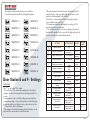
VD 950
Door Station
AC Input
2
2
2
2
2
2
POWER SUPPLY
PS-50/PS55
VD-950 WIRING DIAGRAM
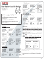
DIP SWITCHES SETTINGS OF DOOR STATION:
FIRST DOOR STATION
SECOND DOOR STATION
THIRD DOOR STATION
FOURTH DOOR STATION
MONITOR 1 MONITOR 9
MONITOR 13
MONITOR 14
MONITOR 12
MONITOR 11
MONITOR 15
MONITOR 16
MONITOR 10
MONITOR 7
MONITOR 8
MONITOR 6
MONITOR 5
MONITOR 4
MONITOR 3
MONITOR 2
DIP SWITCHES SETTINGS OF MONITOR:
There are 6 Dip Switches in total,and each monitor MUST be
set with the correct code.
If daisy chain connection used,dip switch # 6 should be set
ON only on the monitor is at the end of the line.
If parallel connection used, all monitors should have the dip
switch # 6 set ON.
DPS
Dip switches 3 and 4 are inactive, so set them OFF.
For Door Station Model B, please refer to Dip Switches 17-32
on the next page.
Page 03

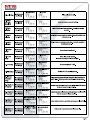
MONITOR 17 MONITOR 25
MONITOR 29
MONITOR 30
MONITOR 28
MONITOR 27
MONITOR 31
MONITOR 32
MONITOR 26
MONITOR 23
MONITOR 24
MONITOR 22
MONITOR 21
MONITOR 20
MONITOR 19
MONITOR 18
Page 04
If you have Door Station B, the monitors connected to the
second button must be set with the following Dip Switches:
Door Station E and F - Settings
Instructions:
* Use " * " to cancel, and "#" to conrm.
* You should press "#” to conrm after inputting the code numb er
each time, otherwise, the set up will be cancelled automatically in 10
seconds.
*. Input the master code to switch the setting mode, and input the
corresponding setting code to perform the function. After setting has
been saved, input the next setting code to continue the set up. Press
" * " at any time to exit the setting mode.
* Each setting is indicated by the lighting of the LED indicators on the
right side of the unit, and by the sound of the buzzer.
* When the registered code has been input on the keypad, the LED
indicator (Group 1: red, group 2: blue) lights up, the buzzer s ounds,
and the door strike/magnetic lock is unlocked.
*User Group 1 codes are linked to the rst lock, and User Group 2
codes are linked to the second lock.
* If you make a mistake when inputting the user code, press “#” to
cancel and input the user code again.
* If 10 continuous incorrect access codes are attempted, the release
function will be disabled for 60 seconds, the LED lights will stay on for
60 seconds, and the door station will beep 8 times.
SETTINGS SETTING RANGE DEFAULT
SETTING
CODE
1 Reset all settings 1,2,3,4 - 00
2 Setting the master code
1 – 12 digits
Valid keys: 0 - 9
1, 2, 3, 4 01
3 Setting the lighting time 10 to 99 seconds
10
seconds
02
4 Setting the unlock time 1 – 99 seconds 1 second 03
5 Setting the unlock mode
0: Open
1: Closed
Open 04
6 Keypad tone settings
0: On
1: Off
On 05
7 Reset code settings 1, 2, 3, 4 - 06
8 *and # settings
0: Normal
1: Reverse
Normal 07
9 Call tone settings
0: Enable
1: Disable
Enable 08
10
Interference resistant grade
settings
Valid Keys: 0 - 5 2 09
12
Setting the code for
Temporary 1
1 – 12 digits
Valid Keys: 0 - 9
- 18
13
Setting the code for
Temporary 2
1 – 12 digits
Valid Keys: 0 - 9
- 19
14
Setting the code for
User Group 1
1 – 12 digits
Number of codes: 40
Valid Keys: 0 - 9
- 20 – 59
15
Setting the code for
User Group 2
1 – 12 digits
Number of codes: 40
Valid Keys: 0 - 9
- 60 - 99


Page 06
Door Station G and H – Settings:
1. ID Card Registration:
Introduction:
1.1.4 Delete all user cards:
1.3 Authorize Master Cards:
When registering new master cards,
the old ones will be deactivated automatically.
*Up to 1000 user cards can be registered to the door station.
*Easy management with LED status and sound hints.
*There are two master cards, one MASTER CARD ADD, and one
MASTER CARD DELETE.
*Card reading distance is from 1 to 2 in (3 to 5 cm).
*The master cards are necessary when you add or delete user cards.
Please keep it for future use.
1.1 Add User Cards:
1.2 Delete User Cards:
1.1.3 Delete User Cards:
1.1.2 Control two locks:
2. Unlock Setting:
When holding the registered user card in front of the door statWhen holding the
lock: red, the second lock: blue) lights up, the buzzer sounds, and the door strike/
magnetic lock will be unlocked.
1 Lock: Show the user card to the ID card window to release the lock, Red LED
lights up;
2 Locks: Show the user card to the ID card window while in standby mode, the
press the CALL button to release the second lock.
Release the first lock Release the second lock
Red LED lights up
Red LED lights up
If 10 continuous unauthorized user cards are attempted, the release function will
bedisabled for 60 seconds.
If unauthorized user card is shown to the ID card window, the buzzer will beep
3 times.
MASTER
CARD
ADD
MASTER
CARD
DELETE
-
 1
1
-
 2
2
-
 3
3
-
 4
4
-
 5
5
-
 6
6
-
 7
7


Entryvue VD-950 User manual
- Category
- Door intercom systems
- Type
- User manual
Ask a question and I''ll find the answer in the document
Finding information in a document is now easier with AI
Related papers
Other documents
-
 Lenel OnGuard Hardware Installation Manual
-
 Schick Handel DMR18 User manual
-
V-Tec VT596/KP User manual
-
ACT ACTPRO 3000 ACCESS CONTROL UNITS Operating instructions
-
-
Videx DIGITAL VX2200 System Manual
-
Interlogix Alliance Builder User manual
-
 fortessa Analogue Door Entry User manual
-
 DMP Electronics SCS-1R User manual
-
Bosch 8500 User manual


