Page is loading ...

Installation Instructions 4-19-02
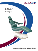
Model BDS-2530
Clesta Swing-Mount Light
Installation Time: Approximately 1 hour
Tools Needed:
Metric Allen Wrench Set
Phillips Head Screw Driver
Masking Tape
Attaching the Chair Mounting Plate
1. Plug chair into a 115 VAC outlet and raise seat.
2. Remove lower seat upholstery from chair.
3. Unplug chair from outlet.
4. Remove the four M4 x 10 Phillips head screws (B6204010) from the chair mounting
bracket and set aside.
5. Hold the chair mounting plate with the M4 x 10 threaded holes on bottom of mounting
plate, facing the floor.
6. Attach mounting plate to chair (Bel 20 or AcuTrac) using socket head bolts and spring
washers.
Attaching the Light Swing Arm
1. Insert four M10 x 20 (B7210020) leveling set screws into threaded holes on the top
side of the rotation bracket assembly while the arm assembly resting on the foam box
packing material.
2. Partially thread one M10 x 40 bolt (B8210040) and spring washer (BW2100SP) into a
threaded hole on top of the mounting bracket, toward the seat. This partially installed
bolt will be used to hold the rotation bracket/swing arm assembly in the next step.
1

3. Lift the swing arm assembly out of the foam packing and place the rotation bracket on
top of the chair mounting plate. Slide the rotation bracket toward the seat and align the
slots on the end of the bracket with the partially installed bolt and spring washer from
the previous step.
4. Insert two M10 x 40 bolts/spring washers into front holes that are recessed into the
top of the rotation bracket assembly and tighten.
• For AcuTrac: Tighten the remaining bolt/spring washer into the remaining hole at the
slotted end of the rotation bracket. Re-tighten all bolts.
• For Bel 20: Remove the partially installed M10 x 40 bolt and spring washer from the
slotted end of the rotation bracket. Place the bracket for umbilical hose (FATB45A0)
on top of the slotted area on the rotation bracket.
Insert the two remaining M10 x 40 bolts/ spring washers through the holes in
the hose bracket and tighten. Retighten all bolts.
5. Plug chair into the 115VAC outlet and lower the chair.
Unplug the chair before proceeding.
Assembling the Upper Clesta Light Post
1. Remove the AL-520X Clesta light assembly and L-Type Light Pole (FGAA14A0)
from the box. Remove the two white Allen cap head screws from the end of the
AL-520X light.
2. Remove plastic sleeve from the end of the upper wire harness (black) and wrap the
wire connectors sparingly with one wrap of masking tape to make insertion into the
swing arm easy. DO NOT OVERWRAP the end of the wire harness or it will not fit
inside swing arm.
3. Thread wire harness through the end of the L-Type Light Pole that has two holes on
top and push completely through the pole. Insert the end of the AL-520X light into
the end of the pole and align the two holes on top of the pole with the threaded holes
inside. Re-tighten white Allen cap head screws.
Attaching the Upper Clesta Light Post Assembly Onto The Light Swing Arm
1. Lift the Clesta light assembly and thread the wrapped end of the wire harness
completely through the lower swing arm assembly. Install Clesta light assembly onto
the swing arm.
2

2. In the small threaded hole at the base of the L-Type Light Pole, insert one brass brake
shoe (FAAA34A0) and set screw (B7206010) and tighten. Gently rotate the pole
back and forth and re-tighten set screw. This set screw will require re-tightening
periodically, especially during the first days of use. Extra brass brake shoes have been
included with the light for replacement of brake shoes as they wear out.
Leveling The Clesta Light Arm Assembly
1. Loosen the four M10 x 40 bolts that hold the rotation
bracket onto the chair mounting plate. Using the four M10 x 20 set screws on top of
the rotation bracket, level the light swing assembly. Re-tighten the M10 x 40 bolts
light has been leveled.
Unpacking The Transformer and Switch Box
1. Remove the Transformer and Switch Box (white) from the AL-520X packaging.
The Transformer should be placed on the floor, within the J-Box frame (for external
umbilical installation) or within the long pump cover of an AcuTrac chair.
2. Remove the cover from the Switch Box by unscrewing the two retaining screws on each side
side of the cover.
Lower Wire Harness (Gray) Installation
• For Bel 20 or AcuTrac with short pump cover/ external umbilical:
Thread the Gray wire harness through the umbilical hose assembly
(FGTA25A0/FGNA30A0) so the rectangular wire connectors can be
connected to the transformer on the floor. Clip the upper end of the umbilical
hose into the bracket (FATB45A0) on top of the rotation bracket.
• For AcuTrac with internal umbilical:
Remove two Phillips head screws from the sides of the metal lift arm covers
(near the chair base). Lift metal covers off of threaded studs to allow the
plastic safety shut off plate to fall flat against the chair base.
Insert the lower wire harness (Gray) with the transformer connectors through
the central rotation hub inside the chair seat area. The wire harness should be
pulled through the inside of the chair lift arm frame and through the area
between the pump and circuit board box on the chair base. The wire harness
can be loosely connected to the lift arm frame with one or two plastic cable ties.
3

Thread the upper end of the (Gray) wire harness underneath the springs and
Out of the seat through the hole in the plastic cover.
Re-fit the plastic safety shut-off plate inside the metal lift arm side covers and
replace and tighten the two Phillips Head screws.
Connecting the Upper and Lower Wire Harnesses to the Switch Box
1. Attach the connectors from both wire harnesses to the connector attached to the wire of
the same color.
Note: there are two dark blue wires to be connected inside the Switch Box. To avoid
installation errors, male and female plastic connectors have been attached to the ends of
the wires.
2. Secure the Gray wire harness inside the built-in strain relief clamps inside of the Switch
Box.
Slip both Black and Gray wire harnesses through the plastic retaining clip on the side of
the Switch Box housing.
Bundle all wires within the Switch Box enclosure and re-attach the cover using the two
screws.
3. Mount the Switch Box on the underside of the chair mounting plate using the four
M4 x 10 Phillips Head screws removed prior to attaching the chair mounting plate.
4. Retain both the Black and Gray wire harnesses to the rotation shaft on the Rotation
Bracket, using the C clamps provided.
Finishing Up
• Replace lower seat upholstery on the chair.
• Plug the Transformer into a 115 VAC outlet and verify that light is functioning
correctly.
• Plug in the chair.
4
/