Page is loading ...

colorCONTROL
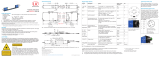
Angle Sensor ACS1
FCS-X-ACS1-45/0-38-XXXX
Mount the sensor to the three mounting holes. Use three cylinder head screws M4x45.
5
0
15 (.59)
23 (.91)
55 (2.17)
89 (3.50)
45°
Target
0
32 ±0.5 (1.26 ±.02)
105 ±1 (4.13 ±.04)
38 ±1 (1.50 ±.04)
23.5 ±0.5 (.93 ±.02)
40
(1.57)
Bending radius
fiber optics
greater than
70 mm (2.76 “)
Optimum
measuring
distance
65 ±1
(2.56 ±.04)
The receiver optics must be positioned vertically above the measurement object.
The optimum distance between measurement object and sensor is near the center of the working
range. Alternatively, use the web interface (Video/Spectrum program area) to set amplitude to
maximum.
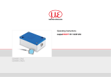
Controller
Place the controller on a level surface or install it for example in a switch cabinet using a DIN EN
60715 mounting rail (DIN rail TS35).
i
When attaching the controller, ensure that no connections, operating or display elements are
covered. Free space adjacent to the heat sink on the right side of the controller: min. 3 cm.
To remove the controller, push it upwards and pull it forwards.
120 (4.72)
211 (8.31)
123.80 (4.87)
(Feets can be removed)
76.2 (3.0)
81.2 (3.2)
appr.
63
DIN rail
fastener
R70
i
When connecting the optical fiber connectors, you need to ensure that the end points do not
touch any edges or surfaces to avoid damage.
Connect the sensor cable (thick strand, larger connector) to the controller.
Guide the coding keys upwards along the fiber connectors, until they fit into the controller’s
grooves. Carefully tighten the union nut by hand.
Connect the signal connector to the controller.
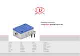
1
2
3
4
5
7
8
9
10
6
1 On/off switch 7 Ethernet / EtherCAT
2 Pushbutton, LED Teach color 8 Light source
3 Pushbutton, LED White reference 9 Sensor connector
4 Pushbutton, LED Dark reference
1
10 RS422, color, digital I/O and supply connectors
5 LED Measurement 1) Set to factory setting: Press the pushbuttons Dark
reference and Teach color approx. 10 s.
6 LED Status
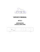
colorCONTROL
Angle Sensor ACS1
FCS-X-ACS1-30/0-50-XXXX
Mount the sensor to the three mounting holes. Use three cylinder head screws M4x45.
5
(.20 dia.)
0
17.5
±0.5 (.69 ±.02)
24.5 ±0.5 (.96 ±.02)
99 ±1 (3.90 ±.04)
0
20 (.79)
63.5 (2.5)
68
±1
(2.68 ±.04)
50 ±2 (1.97 ±.08)
Target
Optimum
measuring
distance
14 (.55)
40 (1.57)
30°
40
(1.57)
Bending radius
fiber optics
greater than
70 mm (2.76 “)
The receiver optics must be positioned vertically above the measurement object.
The optimum distance between measurement object and sensor is near the center of the working
range. Alternatively, use the web interface (Video/Spectrum program area) to set amplitude to
maximum.
Assembly Instructions
colorCONTROL ACS7000
Angle sensor ACS1
Circular sensor ACS2
Transmission sensor ACS3
Tactile adapter ACS1-30/0
Functions
- Noncontact online color measurement
- Color recognition from a taught reference list
- Triggering, synchronization
- Ethernet/EtherCAT, RS422, digital I/O
- Measurement frequency up to 2000 Hz
Warnings
Connect the power supply in accordance to the safety regulations for electrical equipment. The
power supply may not exceed the specified limits.
> Danger of injury, damage to or destruction of the system.
Protect the optical fiber ends from dirt and contamination, protect the cables from damage.
> Failure of the measurement device
Avoid shock and vibration to the controller or the sensor.
> Damage to or destruction of the system
Proper Environment
- Protection class: IP 40 (controller)
IP 64 (sensor)
- Operating temperature: 0 ... +45 °C (+32 ... +113 °F)
- Storage temperature: -20 ... 70 °C (-4 ... +158 °F)
For further informations about the system read the instruction manual.
MICRO-EPSILON Eltrotec GmbH
Manfred-Wörner-Straße 101 · 73037 Göppingen
www.micro-epsilon.com
X9771252.01-A021059HDR
*X9771252.01-A02*

colorCONTROL
Transmission sensor ACS3
FCS-X-ACS3-TRX-200-XXXX (Receiver)
FCS-X-ACS3-TT15-200-XXXX (Transmitter)
1200
1200 (47.2)
96 (3.78)
40 (1.57)
M30x1.5
Transmitter (TT)
Receiver (TR)
M18x1
L
37 (1.46)
49 (1.93)
23 (.91)
dR
15 (.59)
27
(1.06)
16 (.63)
5 (.20)
4
(.16)
0
50
17.3
70
0
50
63
FCS-ACS3 mounting adapter, standard
0
17.3
50
100
120
0
100
113
FCS-ACS3 mounting adapter 50 mm
FCS-X-ACS3-TR5-200-XXXX dR = 5 mm (.20 mm) L = max. 100 mm (3.94 mm)
FCS-X-ACS9-TR5-200-XXXX dR = 9 mm (.35 mm) L = max. 200 mm (7.87 mm)
30
19
ø4.5
316
0
10
40
60
90
110
140
150
160
190
254
284
300
50 ... 200
17.3
18
50
0
150
200
17.3
220
0
200
213
FCS-ACS3-200 mounting rail FCS-ACS3 mounting adapter 150 mm
FCS-ACS Adapter TT-TR
suitable for FCS-X-ACSX
Couples the ACS illumination (FA1 connector)
as alignment aid onto the ACS receiving fibers
(DIN connector).
Installation without mounting-rail
First step: Aligning the transmitter towards the receiver.
Connect the transmitter to the controller and switch on the light source.
Align the transmitter towards the receiver in such a way that the latter is in the center of the
illumination spot.
Second step: Aligning the receiver towards the transmitter.
Use the FCS-ACS adapter TT-TR in order to connect the receiver to the LED light source in
the controller.
FCS-ACS adapter TT-TR
Align the receiver in such a way that the transmitter is in the center of the light spot generated
by the receiver.
Remove the adapter. Connect the transmitter to the light source and the receiver to the spec-
trometer entrance.
colorCONTROL
Tactile Adapter
FCS-ACS1-30/0 Adapter tactile
for sensor FCS-X-ACS1-30/0-50-XXXX
NOTICE
Observe the sensor mounting instructions in the instruction manual,
see Chap. 4.5.
Procedure:
Move the sensor into the adapter until mechanical stop, see Figure A.
Mount the sensor in the adapter using the supplied screws.
52 (2.05)
101
0
18
152
101 (3.98)
22 (.87)
0
18
(.71)
152
(5.98)
2x Ø2 mm
2x Ø2 mm
The adapter enables it, to test
samples for the quality control
at a random check with defined
distance, angle and ambient
conditions.
Figure A
colorCONTROL
Circular sensor ACS2
FCS-X-ACS2-R45/0-28-XXXX
Attach the sensor either laterally to the two or from above to the four mounting holes.
Use cylinder head screws M3x18.
50 (1.97)
2 x M3
6
1200 (47.3)
0
24.8 (.98)
30 (1.18)
28 ±1
(1.10)
ø115
(4.53 dia.)
50 (1.97)
ø72 (2.83)
4 x M3
6
Optimum measuring
distance
Target
(25)
The receiver optics must be positioned vertically above the measurement object.
The optimum distance between measurement object and sensor is near the center of the working
range. Alternatively, use the web interface (Video/Spectrum program area) to set amplitude to
maximum.
/