MICRO-EPSILON capaNCDT 6110/6120 User manual
- Type
- User manual
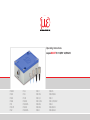
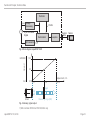
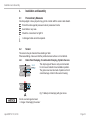
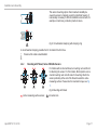
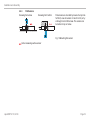
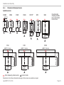
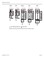
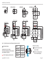
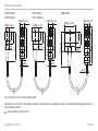
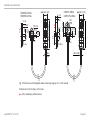
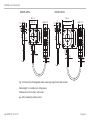
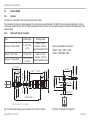
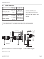
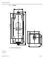
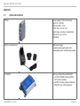
MICRO-EPSILON capaNCDT 6110/6120 is a non-contact capacitive displacement measuring system designed for industrial applications. It offers precise and reliable measurement of displacement, distance, thickness, and movement. The system consists of a sensor, sensor cable, and display/output device. The sensor is available in various sizes and shapes to suit different measurement requirements. It features a robust design and is suitable for use in harsh industrial environments.
MICRO-EPSILON capaNCDT 6110/6120 is a non-contact capacitive displacement measuring system designed for industrial applications. It offers precise and reliable measurement of displacement, distance, thickness, and movement. The system consists of a sensor, sensor cable, and display/output device. The sensor is available in various sizes and shapes to suit different measurement requirements. It features a robust design and is suitable for use in harsh industrial environments.


-
 1
1
-
 2
2
-
 3
3
-
 4
4
-
 5
5
-
 6
6
-
 7
7
-
 8
8
-
 9
9
-
 10
10
-
 11
11
-
 12
12
-
 13
13
-
 14
14
-
 15
15
-
 16
16
-
 17
17
-
 18
18
-
 19
19
-
 20
20
-
 21
21
-
 22
22
-
 23
23
-
 24
24
-
 25
25
-
 26
26
-
 27
27
-
 28
28
-
 29
29
-
 30
30
-
 31
31
-
 32
32
-
 33
33
-
 34
34
-
 35
35
-
 36
36
-
 37
37
-
 38
38
-
 39
39
-
 40
40
-
 41
41
-
 42
42
-
 43
43
-
 44
44
-
 45
45
-
 46
46


MICRO-EPSILON capaNCDT 6110/6120 User manual
- Type
- User manual
MICRO-EPSILON capaNCDT 6110/6120 is a non-contact capacitive displacement measuring system designed for industrial applications. It offers precise and reliable measurement of displacement, distance, thickness, and movement. The system consists of a sensor, sensor cable, and display/output device. The sensor is available in various sizes and shapes to suit different measurement requirements. It features a robust design and is suitable for use in harsh industrial environments.
Ask a question and I''ll find the answer in the document
Finding information in a document is now easier with AI
Related papers
-
MICRO-EPSILON CSE2-M16 Operating Instructions Manual
-
 MICRO-EPSILON capaNCDT 6222 User manual
-
 MICRO-EPSILON capaNCDT 6200 User manual
-
 MICRO-EPSILON DT6120/IP Quick Manual
-
 MICRO-EPSILON capaNCDT 6112 User manual
-
 MICRO-EPSILON capaNCDT 61x4 User manual
-
 MICRO-EPSILON IF1032/ETH User manual
-
 MICRO-EPSILON IF1032/ETH User manual
-
-
MICRO-EPSILON thermoMETER CS Assembly Instructions


Other documents
-
 Soundworld CS10 Quick start guide
-
Infinity IRS Epsilon Owner's manual
-
Crystorama 8854-PN User manual
-
-
 Mono Epsilon 400 Operating And Maintenance Manual
-
Cisco AIR-CT5500-RK-MNT Datasheet
-
Channel Plus 6110 Owner's manual
-
Chromalox CS3 User manual
-
G&D HardBoot CCX Installation and Operating Guide
-
 Air Techniques CamX Elara Intraoral Camera Owner's manual


