Page is loading ...

CSHA2FL-CRa5
CSHA2FL-CRa15
Operating Instructions
capaNCDT 6114/6124

MICRO-EPSILON
MESSTECHNIK
GmbH & Co. KG
Königbacher Straße 15
94496 Ortenburg / Deutschland
Tel. +49 (0) 8542 / 168-0
Fax +49 (0) 8542 / 168-90
e-mail info@micro-epsilon.de
www.micro-epsilon.com
Active capacitive measuring system
for long signal transmission paths

capaNCDT 61x4
Contents
1. Safety ........................................................................................................................................ 5
1.1 Symbols Used ................................................................................................................................................. 5
1.2 Warnings .......................................................................................................................................................... 5
1.3 Notes on CE Marking ...................................................................................................................................... 6
1.4 Intended Use ................................................................................................................................................... 6
1.5 Proper Environment ......................................................................................................................................... 7
2. Functional Principle, Technical Data ...................................................................................... 8
2.1 Measuring Principle ......................................................................................................................................... 8
2.2 Structure .......................................................................................................................................................... 9
2.2.1 Sensors ........................................................................................................................................ 11
2.2.2 Sensor Cable................................................................................................................................ 11
2.2.3 Controller ...................................................................................................................................... 12
2.3 Technical Data for Controllers ....................................................................................................................... 13
2.4 Technical Data for Sensors ............................................................................................................................ 14
3. Delivery .................................................................................................................................. 15
3.1 Unpacking/Included in Delivery .................................................................................................................... 15
3.2 Storage .......................................................................................................................................................... 15
4. Installation and Assembly ...................................................................................................... 16
4.1 Precautions .................................................................................................................................................... 16
4.2 Sensor ............................................................................................................................................................ 16
4.3 Sensor Cable ................................................................................................................................................. 17
4.4 Controller ....................................................................................................................................................... 18
4.5 Ground Connection, Grounding.................................................................................................................... 18
4.6 Power Supply, DT6114 Display/Output Device ............................................................................................. 19
4.7 Power Supply, DT6124 Display/Output Device ............................................................................................. 19
4.8 Sensor Connection ........................................................................................................................................ 20

capaNCDT 61x4
5. RS485 Interface ...................................................................................................................... 21
5.1 Hardware Interface ........................................................................................................................................ 21
5.2 Protocol .......................................................................................................................................................... 21
5.2.1 Reading Measurements ............................................................................................................... 22
5.2.2 Scaling of Measurements ............................................................................................................ 23
5.2.3 Example for Transmitting Measurements .................................................................................... 24
5.2.4 Setting the RS485 Address .......................................................................................................... 26
5.3 Commands and Settings ............................................................................................................................... 27
6. Operation ................................................................................................................................ 28
7. Maintenance ........................................................................................................................... 29
8. Liability for Material Defects .................................................................................................. 30
9. Decommissioning, Disposal .................................................................................................. 30
Appendix
A 1 Optional Accessories ............................................................................................................. 31
A 2 Effect of Capacitive Sensor Tilt ............................................................................................. 32
A 3 Measurement on Narrow Targets .......................................................................................... 33
A 4 Measurement on Spheres and Shafts ................................................................................... 34

Page 5
Safety
capaNCDT 61x4
1. Safety
System operation assumes knowledge of the operating instructions.
1.1 Symbols Used
The following symbols are used in these operating instructions:
Indicates a hazardous situation which, if not avoided, may result in minor or moderate injury.
Indicates a situation that may result in property damage if not avoided.
Indicates a user action.
i
Indicates a tip for users.
Measurement
Indicates hardware or a software button/menu.
1.2 Warnings
Connect the power supply and the display/output device according to the safety regulations for electrical
equipment.
> Risk of injury
> Damage to or destruction of the sensors and/or the controller
Disconnect the power supply before touching the sensor surface.
> Risk of injury
> Static discharge

Page 6
Safety
capaNCDT 61x4
The supply voltage must not exceed the specified limits.
> Damage to or destruction of the sensors and/or the controller
Avoid shocks and impacts to the sensor and the controller.
> Damage to or destruction of the sensors and/or the controller
Protect the sensor cable against damage.
> Destruction of the sensor
> Failure of the measuring system
1.3 Notes on CE Marking
The following apply to the capaNCDT CST61x4:
- EU Directive 2014/30/EU
- EU Directive 2011/65/EU
Products which carry the CE mark satisfy the requirements of the EU directives and the harmonized European standards (EN) listed
therein. The system is designed for use in industrial and laboratory environments and meets the requirements. The EU Declaration of
Conformity is available to the responsible authorities according to EU Directive, Article 10.
1.4 Intended Use
- The capaNCDT 61x4 is designed for use in an industrial environment. It is used for
displacement, distance and movement measurement, thickness measurement,
measuring the position of parts or machine components
- The measuring system must only be operated within the limits specified in the technical data, see Chap. 2.3.
The system must be used in such a way that no persons are endangered or machines and other material goods are damaged in the
event of malfunction or total failure of the system.
Take additional precautions for safety and damage prevention in case of safety-related applications.

Page 7
Safety
capaNCDT 61x4
1.5 Proper Environment
- Protection class: IP 40
- Temperature range (operation)
Sensor, sensor cable: -40 ... +80 °C
Controller: +10 ... +60 °C
- Temperature range (storage)
Sensor, sensor cable: -10 ... +75 °C
Controller: -10 ... +75 °C
- Humidity: 5 - 95% (non-condensing)
- Ambient pressure: Atmospheric pressure

Page 8
Functional Principle, Technical Data
capaNCDT 61x4
2. Functional Principle, Technical Data
2.1 Measuring Principle
The capacitive distance measuring principle of the capaNCDT system is based on the functioning of an ideal plate capacitor. In the
case of conductive targets, the sensor and the target located opposite form the two plate electrodes.
If a constant alternating current flows through the sensor capacitor, the amplitude of the alternating voltage at the sensor is directly
proportional to the distance between the capacitor electrodes. The alternating voltage is rectified, amplified and output as an analog
signal.
The capaNCDT system evaluates the reactance X
C
of the plate capacitor, which varies in strict proportion with the distance:
X = ; capacitance C = * *
c
1
j C
area
distance
r
o
i
A target that is too small and measured surfaces that are curved (uneven) also produce a non-linear characteristic curve.
This theoretical correlation is reproduced almost perfectly in practice
if the sensors are designed as guard ring capacitors.
A linear characteristic curve can be obtained without additional
electronic linearization for the measurement signal if targets consist-
ing of electrically conductive materials (metals) are measured. Minor
changes in the conductivity or magnetic properties do not affect the
sensitivity or linearity.
Electrical conductor
Ground
Screening electrode
Measuring electrode
Fig. 1 Structure of a capacitive sensor

Page 9
Functional Principle, Technical Data
capaNCDT 61x4
2.2 Structure
The non-contact single-channel measuring system of the capaNCDT 61x4 is accommodated in an aluminum housing and consists of the
following components:
- Controller
- Sensor
- Sensor cable
- Power supply and signal cable
The signal processing electronics with the oscillator and demodulator can be found in the controller
1
.
9...36 V
5 pol. connector
Signal
f
OSZ
31 kHz
Oscillator
Demodulator Preamplifier
Active
sensor
Sensor
cable
Voltage
processing
Fig. 2 Block diagram of capaNCDT 6114
1) DT6124 controller: Additionally includes an AD converter for conversion to an RS485 interface.

Page 10
Functional Principle, Technical Data
capaNCDT 61x4
9...36 V
6 pol. connector
Signal
f
OSZ
31 kHz
Oscillator
Demodulator Preamplifier
Active
sensor
Sensor
cable
Voltage
processing
A/D converter
Fig. 3 Block diagram of capaNCDT 6124
Sensor
10 V
5 V
0 V
Target
Measuring range (MR)
Displacement, mm
100 %0 % 50 %
0xF00000
0x0
RS485
1
Fig. 4 Term definition, signal output
1) Only in connection with DT6124 controller

Page 11
Functional Principle, Technical Data
capaNCDT 61x4
2.2.1 Sensors
Sensors with an integrated preamplifier can be used in the measuring
system.
Min. target
diameter
For accurate measurement results, keep the front of the sensor clean
and avoid damaging it.
The capacitive measuring method is area-based. A minimum area is re-
quired depending on the sensor model and measuring range, see Fig. 5.
Sensor model Measuring range, nominal Min. target diameter
CSHA2FL 2 mm 17 mm
Fig. 5 Sensors for electrically conductive targets (metals)
The preamplifier integrated in the sensor generates and amplifies the distance-dependent measurement signal.
2.2.2 Sensor Cable
The 5-pin sensor cable is firmly connected to the sensor. The robust sensor cable connects the sensor to the controller. It is suitable
for use in drag chains and robots, for example.
Switch off the controller when disconnecting or altering the cable connection.
Do nut crush the sensor cable. Do not make any changes to the sensor cable.
Loss of functionality!

Page 12
Functional Principle, Technical Data
capaNCDT 61x4
2.2.3 Controller
The DT61x4 controller contains a voltage processor, oscillator, demodulator and an output stage.
The voltage processor generates all required internal voltages from the supply voltage. The oscillator supplies the sensor with an
alternating voltage that has a constant frequency and amplitude. The frequency is 31 kHz. The demodulator and output stage trans-
form the measurement signal into a standardized voltage signal. The DT6124 controller also includes an analog-digital converter. This
converts the measurement signal and outputs it on the RS485 interface.
HINWEIS
The output voltage can reach a maximum value of 13 VDC if the sensor is unplugged or if the measuring range
is exceeded.
> Damage to downstream devices
Sensor
Supply/
Output
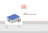
Fig. 6 DT6114 controller

Page 13
Functional Principle, Technical Data
capaNCDT 61x4
2.3 Technical Data for Controllers
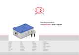
Model DT6114/5 DT6114/15 DT6124/5 DT6124/15
Resolution Static (2 Hz) 0.01% FSO
Dynamic (1 kHz) 0.015% FSO
Frequency response (-3dB) 1 kHz
Measuring rate - - Selectable: max.
2 kSa/s
Selectable: max.
2 kSa/s
Linearity
1
< ±0.1% FSO < ±0.25% FSO < ±0.1% FSO < ±0.25% FSO
Temperature stability < 100 ppm FSO/K
Sensitivity < ±0.2% FSO
Long-term stability < ±0.05% FSO/month
Synchronization no
Supply voltage 9 ... 36 V DC
Power consumption 1.32 W (24 V DC) 1.44 W (24 V DC)
Digital interface - - RS485; 24 bit; 230400 baud (adjustable)
Analog output 0 ... 10 V (short-circuit proof); optional: ± 5 V; 10 ... 0 V
Connection Sensor: 5-pin connector;
Supply/signal: 5-pin connector, SCAC3/5
connection cable included in delivery
Sensor: 5-pin connector;
Supply/signal: 6-pin connector,
SCAC3/6 connection cable included in delivery
Mounting 2 x through-bores for M4 screw
Temperature range Storage -10 ... +75 °C
Operation +10 ... +60 °C
Shock (DIN EN 60068-2-27) 20 g/5 ms, 6 axes, 1000 shocks each, criterion B
Vibration (DIN EN 60068-2-6) 10 Hz ... 49.8 Hz: 1 mm, 49.8 Hz ... 2000 Hz: 10 g, 3 axes 10 cycles each, criterion B
Protection class (DIN EN 60529) IP40
Weight Approx. 165 g
Compatibility Compatible with active CSHA sensors
FSO = Full Scale Output
1) Applies only to controller. The overall linearity of the measuring channel is given by adding up the values for the controller and the sensor.

Page 14
Functional Principle, Technical Data
capaNCDT 61x4
2.4 Technical Data for Sensors
Model CSHA2FL-CRa5 CSHA2FL-CRa15
Measuring range
Reduced 1 mm 1 mm
Nominal 2 mm 2 mm
Extended 4 mm 4 mm
Resolution
1
Industrial 300 nm 300 nm
Linearity
2
< ±2 µm < ±5 µm
Temperature stability
3
< 0.2 µm/K < 0.2 µm/K
Min. target size (flat) Ø 17 mm Ø 17 mm
Connection
Integrated cable, for use with drag chain;
length 5 m, minimum bending radius:
dynamic 60 mm (15 x Ø 4.0 mm)
Integrated cable, for use with drag chain;
length 15 m, minimum bending radius:
dynamic 60 mm (15 x Ø 4.0 mm)
Mounting 4 x through-bores for M2 screw
Temperature range
Storage -40 ... +80 °C
Operation -40 ... +80 °C
Humidity
4
0 … 95 % r.H.
Shock (DIN EN 60068-2-27) 50 g/5 ms, 6 axes 1000 shocks each
Vibration (DIN EN 60068-2-6) 10 Hz ... 46.15 Hz: 3.5 mm, 46.15 Hz ... 2000 Hz: 30 g, 3 axes 10 sweeps each, criterion B
Protection class (DIN EN 60529) IP40
Material 1.4104 (magn.)
Weight approx. 130 g (incl. cable) approx. 360 g (incl. cable)
Compatibility Compatible with capacitive controllers of DT61x4 series by Micro-Epsilon
1) Based on the nominal measuring range
2) Sensor linearity must be added to the controller linearity
3) In recommended mounting position
4) Non-condensing

Page 15
Delivery
capaNCDT 61x4
3. Delivery
3.1 Unpacking/Included in Delivery
1 Controller
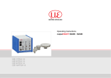
1 Power supply and output cable, SCAC3/5 (DT6114) or SCAC3/6 (DT6124)
1 Quick manual
Optional accessories:
1 Sensor with integrated sensor cable
1 IF1032/ETH interface converter from analog (DT6114) or RS485 Ethernet (DT6124) to Ethernet/EtherCAT
Other optional accessories
Carefully remove the components of the measuring system from the packaging and ensure that the goods are forwarded in such
a way that no damage can occur.
Check the delivery for completeness and shipping damage immediately after unpacking. If there is damage or parts are missing,
immediately contact the supplier.
3.2 Storage
- Storage temperature:
Sensor, sensor cable: -10 ... +75 °C
Controller: -10 ... +75 °C
- Humidity: 5 - 95 % r.H. (non-condensing)

Page 16
Installation and Assembly
capaNCDT 61x4
4. Installation and Assembly
4.1 Precautions
No sharp or heavy objects should be allowed to affect the cable sheath.
Protect the cable from compressive stress in regions exposed to higher pressure
Avoid folding the cables.
Check the plug connections for a tight fit.
4.2 Sensor
During installation, take care that the polished sensor front face is not scratched.
Screwed connection from top The flat sensors are mounted using a threaded bore for M2 (for 0.2
and 0.5 mm sensors) or using a through-hole for M2 screws. The
sensors can be screwed on from above or below.
Fig. 7 Installing the flat sensors
Sensor active measuring area

Page 17
Installation and Assembly
capaNCDT 61x4
15.5
15.5 (.61)
20 (.79)
20
9 (.35)
appr. 37 (1.46)
appr. 8.9
(.35)
Cable length 5 m or 15 m
ø2.2 (4x)
(.09 dia.)
1.6 (.06)
5
0
-0.03
ø4 (4x)
(.16 dia.)
Fig. 8 Dimensional drawing of CSHA2FL-CRAxx flat sensor with integrated cable, measuring range = 2 mm nominal, dimensions in mm
Cable length x = 5 or 15 m
Sensor active measuring area
4.3 Sensor Cable
The sensor is connected to the controller via the sensor cable provided.
This is done simply by plugging it in. The plug connection will lock automatically. You can check that the fit is tight by pulling on the
connector housing (cable socket). You can unlock and release the plug connection by pulling on the knurled housing sleeve of the
cable socket.

Page 18
Installation and Assembly
capaNCDT 61x4
4.4 Controller
12.0
(.47)
52.0 (2.05)
42.0 (1.65)
76.0 (2.99)
appr. 83 (3.27)
Mounting holes
for M4 screws
53.0 (2.09)
30.0 (1.18)
16.5 (.65)
Fig. 9 Dimensional drawing of controller
4.5 Ground Connection, Grounding
Ensure sufficient grounding of the target, for example by connecting it to the sensor or the power supply ground.

Page 19
Installation and Assembly
capaNCDT 61x4
4.6 Power Supply, DT6114 Display/Output Device
The power supply and signal output are provided via the 5-pin connector on the front of the controller.
Pin Wire color
SCAC3/5
Signal Description
View: Solder
side,
5-pin socket
Fig. 10 Supply voltage
connection
Fig. 11 SCAC3/5 power supply
and output cable
The SCAC3/5 is an assembled
supply and output cable that is
3 m long.
1 White +24 V +24 V supply
2 Gray GND Supply ground
3 Yellow - Not used
4 green AGND Analog ground
(for signal output)
5 Brown U-out Signal output
(load, min. 10 kOhm)
Shield Cable shield, housing
4.7 Power Supply, DT6124 Display/Output Device
The power supply and signal output are provided via the 6-pin connector on the front of the controller.
Pin Wire color
SCAC3/6
Signal Description
6
3
2
View: Solder
side,
6-pin socket
Fig. 12 Supply voltage
connection
Fig. 13 SCAC3/6 power supply and
output cable
The SCAC3/6 is an assembled
supply and output cable that is
3 m long.
1 White +24 V +24 V supply
2 Gray GND Supply ground
3 Pink RS485 + RS485 interface
4 Green AGND Analog ground
(for signal output)
5 Brown U-out Signal output
(load, min. 10 kOhm)
6 Blue RS485 - RS485, negated
Shield Cable shield, housing

Page 20
Installation and Assembly
capaNCDT 61x4
4.8 Sensor Connection
Fig. 14 Sensor cable connection
1/36