Page is loading ...

Modular Layer Manure Belt Cage
Installation & Operator’s Instruction Manual
ME1921ANovember 2006

Chore-Time Warranty
2
ME1921A
Chore-Time Equipment (“Chore-Time”) warrants each new Chore-Time product manufactured by it to be
free from defects in material or workmanship for one year from and after the date of initial installation by or
for the original purchaser. If such a defect is found by the Manufacturer to exist within the one-year period,
the Manufacturer will, at its option, (a) repair or replace such product free of charge, F.O.B. the factory of
manufacture, or (b) refund to the original purchaser the original purchase price, in lieu of such repair or
replacement. Labor costs associated with the replacement or repair of the product are not covered by the
Manufacturer.
Conditions and Limitations
1. The product must be installed by and operated in accordance with the instructions published by the
Manufacturer or Warranty will be void.
2. Warranty is void if all components of the system are not original equipment supplied by the Manufacturer.
3. This product must be purchased from and installed by an authorized distributor or certified representative
thereof or the Warranty will be void.
4. Malfunctions or failure resulting from misuse, abuse, negligence, alteration, accident, or lack of proper
maintenance shall not be considered defects under the Warranty.
5. This Warranty applies only to systems for the care of poultry and livestock. Other applications in industry
or commerce are not covered by this Warranty.
The Manufacturer shall not be liable for any Consequential or Special Damage which any purchaser may
suffer or claim to suffer as a result of any defect in the product. “Consequential” or “Special Damages” as
used herein include, but are not limited to, lost or damaged products or goods, costs of transportation, lost
sales, lost orders, lost income, increased overhead, labor and incidental costs and operational
inefficiencies.
THIS WARRANTY CONSTITUTES THE MANUFACTURER’S ENTIRE AND SOLE WARRANTY
AND THIS MANUFACTURER EXPRESSLY DISCLAIMS ANY AND ALL OTHER WARRANTIES,
INCLUDING, BUT NOT LIMITED TO, EXPRESS AND IMPLIED WARRANTIES AS TO
MERCHANTABILITY, FITNESS FOR PARTICULAR PURPOSES SOLD AND DESCRIPTION OR
QUALITY OF THE PRODUCT FURNISHED HEREUNDER.
Chore-Time Distributors are not authorized to modify or extend the terms and conditions of this Warranty
in any manner or to offer or grant any other warranties for Chore-Time products in addition to those terms
expressly stated above. An officer of CTB, Inc. must authorize any exceptions to this Warranty in writing.
The Manufacturer reserves the right to change models and specifications at any time without notice or
obligation to improve previous models.
Effective: November 2006
Chore-Time Equipment
A Division of CTB, Inc.
P.O. Box 2000 • Milford, Indiana 46542-2000 • U.S.A.
Phone (574) 658-4101 • Fax (877) 730-8825
Email: [email protected] • Internet: http//www.ctbinc.com
Chore-Time Warranty

Contents
Topic Page User
ME1921A
* Legend: C = Customer (end user), D = Distributor (sales), I = Installer of equipment
3
Chore-Time Warranty . . . . . . . . . . . . . . . . . . . . . . . . . . . . . . . . . . . . . . . . . . . . . . . . 2 C
About This Manual. . . . . . . . . . . . . . . . . . . . . . . . . . . . . . . . . . . . . . . . . . . . . . . . . . . 4 C,I,D
Safety Information . . . . . . . . . . . . . . . . . . . . . . . . . . . . . . . . . . . . . . . . . . . . . . . . . . . 4 C,I
Safety–Alert Symbol . . . . . . . . . . . . . . . . . . . . . . . . . . . . . . . . . . . . . . . . . . . . . . . . . . . . . . . . . 4
Understanding Signal Word. . . . . . . . . . . . . . . . . . . . . . . . . . . . . . . . . . . . . . . . . . . . . . . . . . . . 4
Follow Safety Instructions. . . . . . . . . . . . . . . . . . . . . . . . . . . . . . . . . . . . . . . . . . . . . . . . . . . . . 5
Decal Descriptions. . . . . . . . . . . . . . . . . . . . . . . . . . . . . . . . . . . . . . . . . . . . . . . . . . . . . . . . . . . 5
DANGER: Moving Auger. . . . . . . . . . . . . . . . . . . . . . . . . . . . . . . . . . . . . . . . . . . . . . . . . . . . . 5
DANGER: Electrical Hazard . . . . . . . . . . . . . . . . . . . . . . . . . . . . . . . . . . . . . . . . . . . . . . . . . . 5
Cage Layout . . . . . . . . . . . . . . . . . . . . . . . . . . . . . . . . . . . . . . . . . . . . . . . . . . . . . . . . 6 I
Placement of Drive Unit . . . . . . . . . . . . . . . . . . . . . . . . . . . . . . . . . . . . . . . . . . . . . . . . . . . . . . .6
Attaching End Rails. . . . . . . . . . . . . . . . . . . . . . . . . . . . . . . . . . . . . . . . . . . . . . . . . . . . . . . . . . 7
Bottom Tier Partition Assembly . . . . . . . . . . . . . . . . . . . . . . . . . . . . . . . . . . . . . . . . . . . . . . . . 8
Assembling the Bottom Tier . . . . . . . . . . . . . . . . . . . . . . . . . . . . . . . . . . . . . . . . . . . . . . . . . . . 9
Attaching Partitions at the end of Each Manure Belt Rail. . . . . . . . . . . . . . . . . . . . . . . . . . . . . 9
Mid Rail Partitions. . . . . . . . . . . . . . . . . . . . . . . . . . . . . . . . . . . . . . . . . . . . . . . . . . . . . . . . . . . 10
Cutting Rails at Idler end. . . . . . . . . . . . . . . . . . . . . . . . . . . . . . . . . . . . . . . . . . . . . . . . . . . . . . 11
Attaching the Idler . . . . . . . . . . . . . . . . . . . . . . . . . . . . . . . . . . . . . . . . . . . . . . . . . . . . . . . . . . . 12
Installing Manure Belt Backs. . . . . . . . . . . . . . . . . . . . . . . . . . . . . . . . . . . . . . . . . . . . . . . . . . . 13
Installing Water Lines . . . . . . . . . . . . . . . . . . . . . . . . . . . . . . . . . . . . . . . . . . . . . . . . . . . . . . . . 14
Installing Floor Supports . . . . . . . . . . . . . . . . . . . . . . . . . . . . . . . . . . . . . . . . . . . . . . . . . . . . . . 15
Assembling Even numbered Tiers (2,4,6,etc.). . . . . . . . . . . . . . . . . . . . . . . . . . . . . . . . . . . . . . 16
Assembling upper Partitions (Tier 2 and above) . . . . . . . . . . . . . . . . . . . . . . . . . . . . . . . . . . . . 16
Installing Even Tier Manure Belt Rails 17
Assembling Odd numbered Tiers (3,5,7,etc.) . . . . . . . . . . . . . . . . . . . . . . . . . . . . . . . . . . . . . . 18
Installing Odd Tier Manure Belt Rails. . . . . . . . . . . . . . . . . . . . . . . . . . . . . . . . . . . . . . . . . . . . 18
Installing Floor. . . . . . . . . . . . . . . . . . . . . . . . . . . . . . . . . . . . . . . . . . . . . . . . . . . . . . . . . . . . . . 19
Installing the Cage Tops . . . . . . . . . . . . . . . . . . . . . . . . . . . . . . . . . . . . . . . . . . . . . . . . . . . . . . 20
Installing Idler end Return Cross Brace. . . . . . . . . . . . . . . . . . . . . . . . . . . . . . . . . . . . . . . . . . . 20
Installing the Partition Braces . . . . . . . . . . . . . . . . . . . . . . . . . . . . . . . . . . . . . . . . . . . . . . . . . . 21
Installing Cable for Doors . . . . . . . . . . . . . . . . . . . . . . . . . . . . . . . . . . . . . . . . . . . . . . . . . . . . . 22
Installing the Litter Shield . . . . . . . . . . . . . . . . . . . . . . . . . . . . . . . . . . . . . . . . . . . . . . . . . . . . . 23
Installing Doors . . . . . . . . . . . . . . . . . . . . . . . . . . . . . . . . . . . . . . . . . . . . . . . . . . . . . . . . . . . . . 24
Installing Trough . . . . . . . . . . . . . . . . . . . . . . . . . . . . . . . . . . . . . . . . . . . . . . . . . . . . . . . . . . . . 25
Part Numbers . . . . . . . . . . . . . . . . . . . . . . . . . . . . . . . . . . . . . . . . . . . . . . . . . . . . . . . 26 I
Itemized Parts . . . . . . . . . . . . . . . . . . . . . . . . . . . . . . . . . . . . . . . . . . . . . . . . . . . . . . . 27 I

About This Manual
4
ME1921A
The intent of this manual is to help you in two ways. One is to follow step-by-step in the order of assembly
of your product. The other way is for easy reference if you have questions in a particular area.
Important ! Read ALL instructions carefully before starting construction.
Important ! Pay particular attention to all SAFETY information.
• Metric measurements are shown in millimeters and in brackets, unless otherwise
specified. “ " ” equals inches and “ ' ” equals feet in English measurements.
Examples:
1" [25.4]
4' [1 219]
• Optional equipment contains necessary instructions for assembly or operation.
• Major changes from the last printing will be listed on the back cover.
• This Planning Symbol is used in areas where planning needs to take place before
construction continues.
• Very small numbers near an illustration (i.e.,
1257-48) are identification of the graphic,
not a part number.
Caution, Warning and Danger Decals have been placed on the equipment to warn of potentially
dangerous situations. Care should be taken to keep this information intact and easy to read at all
times. Replace missing or damaged safety decals immediately.
Using the equipment for purposes other than specified in this manual may cause personal injury
and/or damage to the equipment.
Safety–Alert Symbol
This is a safety–alert symbol. When you see this symbol on your equipment, be alert to the
potential for personal injury. This equipment is designed to be installed and operated as safely as
possible...however, hazards do exist.
Understanding Signal Words
Signal words are used in conjunction with the safety–alert symbol to identify the severity of the
warning.
DANGER indicates an imminently hazardous situation which, if not avoided, WILL result in
death or serious injury.
WARNING indicates a potentially hazardous situation which, if not avoided, COULD result in
death or serious injury.
CAUTION indicates a hazardous situation which, if not avoided, MAY result in minor or
moderate injury.
About This Manual
Safety Information

Safety Information
ME1921A
5
Follow Safety Instructions
Carefully read all safety messages in this manual and on your equipment safety signs. Follow
recommended precautions and safe operating practices.
Keep safety signs in good condition. Replace missing or damaged safety signs.
Decal Descriptions
DANGER: Moving Auger
This decal is placed on the Panel Weldment.
Severe personal injury will result, if the electrical power is not disconnected, prior to servicing the
equipment.
DANGER: Electrical Hazard
Disconnect electrical power before inspecting or servicing equipment unless maintenance instructions
specifically state otherwise.
Ground all electrical equipment for safety.
All electrical wiring must be done by a qualified electrician in accordance with local and national electric
codes.
Ground all non-current carrying metal parts to guard against electrical shock.
With the exception of motor overload protection, electrical disconnects and over current protection are
not supplied with the equipment.
Safety Information

6
ME1921A
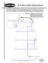
Cage Layout
Placement of Drive Unit
Cage Layout
E
G
G
C
O
N
V
E
Y
O
R
M
A
N
U
R
E
P
I
T
DRIVE UNIT
OVERLAP SHOULD BE
BETWEEN 1/4-1/2 OF THE
CONVEYOR WIDTH
DRIVE UNIT
SUPPORT BRACE
IDLER END
Figure 1. Drive Unit Placement

Cage Layout
7
Attaching End Rails
Thread a 1/2 HX Nut (Item 1, Figure 5) onto a 5/16-18 x 5.00 HH Bolt (Item 2) and attach it to the bottom of the Bottom Drive Unit (Item 3) as
shown. Attach each of the Drive Units together with 3/8 x .75 Cap Screws (Item 4) and 3/8-16 Hex Nuts (Item 5). Attach a Rail Brace (Item 6) to the
Bottom Drive Unit with 5/16-16 Cap Screws (Item 7) and Flange Nuts (Items 8). Attach the MMB Drive End Rail (Item 9) to the Bottom Rail Brace
with 1/4-20 Hardware as shown.
Item Description Part No.
1 1/2 HX Nut 2042
2 5/16-18 x 5.00 4412-14
3 Bottom Drive Unit Varies
4 3/8 x .75 HXHD Cap Screw 2182
5 3/8-16 Hx Nut 1549
6 Rail Brace 48254
7 5/16-18 HXHD Cap Screw 2046
8 5/16-18 HX Flange Nut 8490
9 MMB End Rail 48963
10 1/4-20 x .625 TH Screw 4305
11 1/4-20 Flange Nut 4646
8
9
5
4
1
2
10
6
11
7
Figure 2. Attaching Drive End Rails
3
6

8
ME1921A
Cage Layout
Bottom Tier Partition Assembly
Fasten Bolt Braces (Item 1, Figure 3) to each of the Bottom Manure Belt Legs (Item 2) using 1/4-20 TH Screws (Item 3) and 1/4-20 Flange Nuts
(Item 4) as shown. Thread 5/16" Flange Nuts (Item 5) onto 5/16-18 x 5.00 HH Bolts (Item 6). Insert the Bolts into each of the Bolt Braces and secure
with 5/16-18 Square Nuts (Item 7) as shown. These Bolts will be used to level the Cage Row. Attach a Leg to each end of a Partition (Item 8) by
inserting the partition wires into the Legs and bending the wires down as shown.
Figure 3. Bottom Partition Assembly
1
4
5
6
2
Bend Wires Down
Item Description Part No.
1 Bolt Brace 47587
2 Bottom Manure Belt Leg 50069
3 1/4-20 x .625 TH Screw 4305
4 1/4-20 Flange Nut 46460
5 5/16 Flange Nut 8490
6 5/16-18 x 5.00 HHFTHD Bolt 4412-14
7 5/16-18 Square Nut 39-20244
8 Partition Varies
3

Cage Layout
9
Assembling the Bottom Tier
Attaching Partitions at the end of Each Manure Belt Rail
Orient a Bottom Partition (Item 1, Figure 4) with the Horizontal wires toward the Drive Unit (See Figure). Obtain a Manure Belt Rail (Item 2) and
line up the holes in the end of it with the holes in the End Rail (Item 3) making sure to keep the Manure Belt Rail toward the inside of the End Rail as
shown. Line up the holes in the Leg of a Partition with the same holes, and while keeping the Leg outside of the End Rail, Fasten them all together
with 1/4-20 hardware; Do not tighten down hardware at this time. (See Figure). Attach only the Partitions at the end of each Manure Belt Rail at
this time. The Mid Rail Partitions will be added in the next step. Use the 5/16-18 x 5.00 Threaded Bolts (Item 4) in the Legs to level the Rails. as you
go. Once the 2nd Tier has been assembled, come back and tighten all of the hardware on the bottom Tier.
Figure 4. Attaching End of Rail Partitions
Item Description Part No.
1 Bottom Partition (Assembled in Figure 3)
2 Manure Belt Rail 50427
3 MMB Drive End Rail 48963
4 1/4-20 x .625 TH Screw 4305
5 1/4-20 Flange Nut 46460
6 5/16-18 x 5.00 HHFTHD Bolt 4412-14
Use Threaded Bolt to
Level the Rails
4
5
Do Not Tighten Hardware
Note: Horizontal Wires of Partition
to be toward Manure Drive Unit
4
until next Tier is installed
2
3
1

10
ME1921A
Cage Layout
Mid Rail Partitions
Once a Partition is attached at the end of a Rail, use 1/4-20 hardware to attach the remaining Partitions to that Rail every 24" as shown below. Adjust
each Leg adjustment bolt until it makes full contact with the floor to assure proper leveling. In order to get the exact Cage Row length that you need, it
may be necessary to cut the last Manure Belt Rail. (See next Page).
Figure 5. Attaching Mid-Rail Partitions
Note: the Position of
Horizontal and Vertical
Wires. Horizontal Wires
are to face Drive Unit
Do Not Tighten Hardware
until next Tier is installed
Lower Bolt until Firm
Contact with floor.
Drive Unit

Cage Layout
11
Cutting Rails at Idler end
Once the last Partition is installed, cut the last Manure Belt Rail (Item 1, Figure 6) Flush with the Bottom Leg (Item 2) as shown. De-burr the Rail edge
because it could come in contact with the belt. Cut the sharp corner off of the end of the Manure Belt Rail. De-burr the cut edge to avoid cutting the Belt
when it is installed. Repeat this procedure for each Manure Belt Rail on the other Tiers as they are assembled.
Cut Manure Belt Rail
Flush with outside
of Leg. De-burr edge.
Figure 6. Cutting Rails at Idler end
Item Description Part No.
1 Manure Belt Rail 50427
2 Manure Belt Bottom Leg 50069
This view shown from looking from inside
Use Threaded Bolt to
1
2
to more clearly show the Rail after being cut.
Cut Corner off at
a 45° angle and
De-burr edge.
Cut Rail
Flush with Leg
and De-burr.

12
ME1921A
Cage Layout
Attaching the Idler
Use 1/4-20 hardware to attach the Idler End Rail (Item 1, Figure 7) to the last Manure Belt Rail (Item 2) and the last Partition as shown. Note that the
Bolt Heads are toward the center of the Cage so when the Belt is installed it does not get caught up in the long end of the Bolts. Repeat the same steps to
attach the Idler End Rail on the other side. Choose the set of holes in the Idler Leg (Item 4) that best levels the Idler End Rail and attach it to the Idler
End Rail with 1/4-20 Hardware. Repeat for the other Cage side. The Idler Legs used will vary per the number of Tiers in Cage system (See in parts list).
Attach the Idler Back (Item 5) and Extension Leg (Item 6) to each Idler Leg with 5/16-18 Hardware as shown.
Figure 7. Cutting Rails at Idler end
Item Description Part No.
1 Idler End Rail 48962
2 Manure Belt Rail 48962
3 Last Partition
4 Idler Leg (3-high) 49476
4-high 49004-1
5-high 4192-1
6 high 49476
8 high 49411
5 Idler Back 48969
6 Extension Leg 48056-1,-2
1
2
3
4
5
6

Cage Layout
13
Installing Manure Belt Backs
Obtain a Manure Belt Back (Item 1, Figure 8) and, using the hooks (Item 2) at both ends, hang it at the exact center of two Partitions (Item 3) with the
top most wire resting on the third wire from the top of the Partitions (See Figure). Install the remaining Manure Belt Backs alternating the way in which
they overlap from left and right as shown.
Figure 8. Installing Manure Belt Backs
Item Description Part No.
1 Manure Belt Back 17333
2 Hook
3 Partition
1
2
3
3
Top View
Alternate Manure Belt Backs left and right
as you progress down cage row.
Side View
End View
3rd Wire from
top of Partition

14
ME1921A
Cage Layout
Installing Water Lines
Feed a Nipple Pipe Assembly (Item 1, Figure 9) through the wire square that is one right of the center wire, and at the top of each Partition (See Figure).
The Locator Block (Item 2) on the Nipple Pipe must be located such that it will lie on a horizontal Partition wire. Obtain a Locator Block Support (Item
3) and snap the Locator Block into it. With the Locator Block snapped in place, attach it onto the Partition wire. Attach the pipe to all of the remaining
Partitions with Non-Locator Block Supports (Item 4) (See Figure). Feed a second Nipple Pipe Assembly through the Partitions and insert it into the 1st
Nipple Pipe atleast 2". Attach it to the Partitions just as you did the 1st pipe. Continue with Pipe as needed to the end of the cage row. Be sure to completely
assemble all of the Pipe in a Tier before starting to assemble the next Tier. It is difficult to feed Pipe through the Partitions if the Tier above is in the way.
1
Partition Center Wire
2
3
4
Figure 9. Installing Water Lines
Item Description Part No.
1 Nipple Pipe Assembly
2 Locator Block
3 Locator Block Support 48162-2
4 Non-Locator Block
Support
48162-1
Insert Pipes together 2" [5.1 cm]

Cage Layout
15
Installing Floor Supports
The location of the Floor Supports (Item 1, Figure 10) depends on the Cage type. The correct locations of the Floor Supports for each Cage type is shown
below. Insert the Floor Supports into the proper Partition square, slide it through to the corresponding square on the second Partition, and hook the end
on the horizontal partition wire as shown. The Floor is shown in the Figure, but is not actually installed at this time.
1
Figure 10. Installing Floor Supports
Item Description Part No.
1 Floor Support
P4037-122
20 " Deep Cage with Air
22.34 " Deep Cage with Air
25.34 " Deep Cage with Air
22.34 " Deep Cage without Air
25.34 " Deep Cage without Air

16
ME1921A
Cage Layout
Assembling Even numbered Tiers (2,4,6,etc.)
Assembling upper Partitions (Tier 2 and above)
Attach a Manure Belt Top Leg (Item 1, Figure 11) to both ends of a Partition (Item 2) by inserting the partition wires into the Legs and bending the
them down as shown.
Figure 11. Upper Partition Assembly
Item Description Part No.
1 Manure Belt Top Leg 50068
2 Partition 4412-14

Cage Layout
17
Installing Even Tier Manure Belt Rails
Attach the 2nd Tier End Rail (Item 1, Figure 12) to the Drive Unit just like you did on the 1st Tier. In order to maintain a level cage row, the ends of
the Manure Belt Rails need to be staggered between each Tier. To achieve this, cut 47.9" [121.7cm] off the end of the 1st Manure Belt Rail (Item 2)
on all of the even numbered Tiers (Tier 2,4,6, etc.). Attach the newly cut Manure Belt Rail and a Manure Belt Top Leg (Item 3) to the End Rail using
a Leg Splice (Item 4) and 1/4-20 hardware as shown. Do not tighten the hardware at this time; once the tier that you are working on is completed,
tighten the hardware on the tier directly under it. Attach loosely the remaining Manure Belt Rails and Legs using leg splices and 1/4-20 hardware as
shown. Note: Manure Belt Rail must be toward the inside of the End Rail (See Figure).
Figure 12. Installing Even Tiers
Item Description Part No.
1 MMB Drive End Rail 48963
2 Manure Belt Rail 50427
3 Manure Belt Top Leg 50068
4 Leg Splice 47591
5 1/4-20 x .625 TH
Screw
4305
6 1/4-20 Flg. Nut 4646
1
Cut off and Discard 47.9" of
4
4
5
6
5
6
the 1st Manure Belt Rail on
all even number Tiers (2,4,6,etc.)
2
Manure Belt Rail towards
inside of End Rail
3
Do Not tighten hardware
until the next Tier is installed
Do Not tighten hardware until the next Tier is installed

18
ME1921A
Cage Layout
Assembling Odd numbered Tiers (3,5,7,etc.)
Installing Odd Tier Manure Belt Rails
Attach the odd tier End Rails (Tier 3,5,7,etc.) (Item 1, Figure 13) to the Drive Unit just like you did the other tiers. Attach a Manure Belt Rail (Item
2) and a Manure Belt Top Leg (Item 3) to the End Rail using a Leg Splice (Item 4) and 1/4-20 hardware as shown. Do not tighten the hardware at this
time; once the tier that you are working on is completed, tighten the hardware on the tier directly under it. Note: Manure Belt Rail must be toward the
inside of the End Rail (See Figure). Attach loosely the remaining Manure Belt Rails and Legs using leg splices and 1/4-20 hardware as shown.
Figure 13. Installing Odd Tiers
Item Description Part No.
1 MMB Drive End Rail 48963
2 Manure Belt Rail 50427
3 Manure Belt Top Leg 50068
4 Leg Splice 47591
5 1/4-20 x .625 TH
Screw
4305
6 1/4-20 Flg. Nut 4646
1
4
4
5
6
5
2
3
Full Length Manure Belt Rail
Manure Belt Rail towards
inside of End Rail
Do Not tighten hardware
Do Not tighten hardware
until the next Tier is installed
until the next Tier is installed
6

Cage Layout
19
Installing Floor
Insert Floor Bottoms (Item 1, Figure 14) from each side of the Cage on top of the Floor Supports as shown. Attach the two Floor Bottoms together at
the middle using a ring gun and Wire Rings (Item 2). Capture the end wires of the Floor Bottoms (Item 3) as well as the bottom wire of the Cage Back
(Item 4). Use 9 rings per Partition; one on every 3rd wire section of the Floor Bottoms. Install Edge Guard (Item 5) onto Cage Bottoms using Wire Rings
as shown.
1
Top View- To show Rings every 3rd wire section
2
2
3
Figure 14. Installing Floor
Item Description Part No.
1 Floor Bottom
17488GB
2Wire Ring
3 End Wire of Floor Bottom
4 Bottom Wire of Cage Back
5 Edge Guard E1810
1
1
4
2
5

20
ME1921A
Cage Layout
Installing the Cage Tops
On the Top Tier use a ring gun and Cage Rings to attach a Top (Item 1, Figure 15) per cage section. Use 10 Cage Rings (Item 2) per Partition
approximately 4" [10.2 cm] apart.
Installing Idler end Return Cross Brace
At the Idler end of the cage row attach a Return Cross Brace (Item 1, Figure 16) to the Bottom Manure Belt Legs (Item 2) with #10 Self Drilling Screws
(Item 3) as shown
Figure 15. Installing Tops
1
Approx. 4" [10.2 cm] Typical
2
Item Description Part No.
1 Top 17491
2 Cage Ring E2736
Item Description Part No.
1 Return Cross Brace 47670-X
2 #10 Self Drilling Screw 3037
2
2
1
1
Figure 16. Installing Return Cross Brace
/