Page is loading ...

K-Valve Cage Cup Watering Systems
Installation & Operator’s Instruction Manual
MW1504BMarch 1999

2
Chore-Time K-Valve Cage Cup Watering Systems
Chore-Time Warranty
Chore-Time Equipment warrants each new product manufactured by it to be free from defects in material
or workmanship for one year from the date of initial installation by the original purchaser. If such a defect
is found by Chore-Time to exist within the one year period, Chore-Time will, at its option, (a) repair or
replace such product free of charge, F.O.B. the factory of manufacture, or (b) refund to the original
purchaser the original purchase price, in lieu of such repair or replacement.
Conditions and limitations:
1. The product must be installed and operated in accordance with instructions published by Chore-Time
or warranty will be void.
2. Warranty is void if all components of a system are not supplied by Chore-Time.
3. This product must be purchased from and installed by an authorized Chore-Time dealer or certified
representative thereof, or the warranty will be void.
4. Malfunctions or failure resulting from misuse, abuse, negligence, alteration, accident, or lack of
proper maintenance shall not be considered defects under this warranty.
5. This warranty applies only to systems for the care of poultry and livestock. Other applications in
industry or commerce are not covered by this warranty.
Chore-Time shall not be liable for any Consequential or Special Damage which any purchaser may suffer
or claim to have suffered as a result of any defect in the product. “Consequential” or “Special Damages”
as used herein include, but are not limited to, lost or damaged products or goods, costs of transportation,
lost sales, lost orders, lost income, increased overhead, labor and incidental costs and operational
inefficiencies.
THIS WARRANTY CONSTITUTES CHORE-TIME’S ENTIRE AND SOLE WARRANTY AND
CHORE-TIME EXPRESSLY DISCLAIMS ANY AND ALL OTHER WARRANTIES, INCLUDING,
BUT NOT LIMITED TO, EXPRESS AND IMPLIED WARRANTIES AS TO MERCHANTABILITY,
FITNESS FOR PARTICULAR PURPOSE SOLD AND DESCRIPTION OR QUALITY OF THE
PRODUCT FURNISHED HEREUNDER.
Any exceptions to this warranty must be authorized in writing by an officer of the company. Chore-Time
reserves the right to change models and specifications at any time without notice or obligation to improve
previous models.
CHORE-TIME EQUIPMENT, A Division of CTB, Inc.
P.O. Box 2000
Milford, Indiana 46542-2000 U.S.A.

Table of Contents
Topic Page User*
*Legend: C = Customer (end user), D = Distributor (sales), I - Installer of equipment
Chore-Time Warranty . . . . . . . . . . . . . . . . . . . . . . . . . . . . . . . . . . . . . . . . . . . . . . . . 2 C,D
Support Information . . . . . . . . . . . . . . . . . . . . . . . . . . . . . . . . . . . . . . . . . . . . . . . . . 4 C,D
Distributor and Installer Information . . . . . . . . . . . . . . . . . . . . . . . . . . . . . . . . . . . 4 D,I
Safety Information . . . . . . . . . . . . . . . . . . . . . . . . . . . . . . . . . . . . . . . . . . . . . . . . . . . 5 C,D,I
Safety–Alert Symbol. . . . . . . . . . . . . . . . . . . . . . . . . . . . . . . . . . . . . . . . . . . . . . . . . . . . . . .5
Signal Words. . . . . . . . . . . . . . . . . . . . . . . . . . . . . . . . . . . . . . . . . . . . . . . . . . . . . . . . . . . . .5
Tools Required . . . . . . . . . . . . . . . . . . . . . . . . . . . . . . . . . . . . . . . . . . . . . . . . . . . . . . 5 I
Prior to Installation . . . . . . . . . . . . . . . . . . . . . . . . . . . . . . . . . . . . . . . . . . . . . . . . . . 6 C,D,I
Control Panel Installation . . . . . . . . . . . . . . . . . . . . . . . . . . . . . . . . . . . . . . . . . . . . . 7 I
9275 Control Panel . . . . . . . . . . . . . . . . . . . . . . . . . . . . . . . . . . . . . . . . . . . . . . . . . . . . . . . .7
36802-2 Flushable Filter Control Panel . . . . . . . . . . . . . . . . . . . . . . . . . . . . . . . . . . . . . . . .8
Install Supply Lines from the Control Panel to Manifolds. . . . . . . . . . . . . . . . . . . 8 I
Cage Manifold Installation . . . . . . . . . . . . . . . . . . . . . . . . . . . . . . . . . . . . . . . . . . . . 8 I
Cage rows over 600’ (183 m) . . . . . . . . . . . . . . . . . . . . . . . . . . . . . . . . . . . . . . . . . . . . . . . 10
Component Spacing Diagrams . . . . . . . . . . . . . . . . . . . . . . . . . . . . . . . . . . . . . . . . . 10 I
Waterer Line Installation . . . . . . . . . . . . . . . . . . . . . . . . . . . . . . . . . . . . . . . . . . . . . . . . . . 11
Outlet Drain Installation . . . . . . . . . . . . . . . . . . . . . . . . . . . . . . . . . . . . . . . . . . . . . . . . . . . 12
Installation of the CHORE-TIME K-Valve Cup. . . . . . . . . . . . . . . . . . . . . . . . . . .13 I
Chore-Time K-Valve Cup (No Spout) . . . . . . . . . . . . . . . . . . . . . . . . . . . . . . . . . . . . . . . . 13
Water Line Location. . . . . . . . . . . . . . . . . . . . . . . . . . . . . . . . . . . . . . . . . . . . . . . . . . . . . . 13
Cup Installation. . . . . . . . . . . . . . . . . . . . . . . . . . . . . . . . . . . . . . . . . . . . . . . . . . . . . . . . . . 14
Before Turning On The Water . . . . . . . . . . . . . . . . . . . . . . . . . . . . . . . . . . . . . . . . .16 C,I
Post Installation Check List . . . . . . . . . . . . . . . . . . . . . . . . . . . . . . . . . . . . . . . . . . . . . . . . 16
After turning on the water. . . . . . . . . . . . . . . . . . . . . . . . . . . . . . . . . . . . . . . . . . . . . . . . . . 16
Recommendations and Guidelines for Operation . . . . . . . . . . . . . . . . . . . . . . . . . .17 C,I
Cage Watering System Maintenance . . . . . . . . . . . . . . . . . . . . . . . . . . . . . . . . . . . . 18 C
General Maintenance . . . . . . . . . . . . . . . . . . . . . . . . . . . . . . . . . . . . . . . . . . . . . . . . . . . . . 18
Maintenance Between Flocks. . . . . . . . . . . . . . . . . . . . . . . . . . . . . . . . . . . . . . . . . . . . . . . 18
Chore-Time K-Valve Components. . . . . . . . . . . . . . . . . . . . . . . . . . . . . . . . . . . . . . . . . . . 19
Parts Listing . . . . . . . . . . . . . . . . . . . . . . . . . . . . . . . . . . . . . . . . . . . . . . . . . . . . . . . . 20 C,D,I
9275 Water Filter Control Panel. . . . . . . . . . . . . . . . . . . . . . . . . . . . . . . . . . . . . . . . . . . . . 20
36802-2 Flushable Filter Control Panel . . . . . . . . . . . . . . . . . . . . . . . . . . . . . . . . . . . . . . . 21
30135 K-Valve Inlet Assembly . . . . . . . . . . . . . . . . . . . . . . . . . . . . . . . . . . . . . . . . . . . . . 22
Inlet Manifold Kits for Cage Waterer Lines. . . . . . . . . . . . . . . . . . . . . . . . . . . . . . . . . . . . 23
Chore-Time K-Valve Cage Cup Line Components . . . . . . . . . . . . . . . . . . . . . . . . . . . . . . 24
Cup Assemblies for repair or replacement . . . . . . . . . . . . . . . . . . . . . . . . . . . . . . . . . . . . . 24
Chore-Time K-Valve . . . . . . . . . . . . . . . . . . . . . . . . . . . . . . . . . . . . . . . . . . . . . . . . . . . . . 25
Chore-Time Cage Cup Line Componenets. . . . . . . . . . . . . . . . . . . . . . . . . . . . . . . . . . . . . 25
Installation and Repair Parts for Optional Water Meter. . . . . . . . . . . . . . . . . . . .26 C,D,I
Water Meter and Connectors . . . . . . . . . . . . . . . . . . . . . . . . . . . . . . . . . . . . . . . . . . . . . . . 26
Trouble Shooting Guide. . . . . . . . . . . . . . . . . . . . . . . . . . . . . . . . . . . . . . . . . . . . . . . 27 C,I

4
Chore-Time K-Valve Cage Cup Watering Systems
Support Information
This manual is designed to provide comprehensive planning, installation, operation, and parts listing
information. The Table of Contents provides a convenient overview of the information in this manual. The
Table of Contents also specifies which pages contain information for the sales personnel, installer, and
consumer (end user).
IMPORTANT: CE stands for certified Europe. It is a standard which
equipment must meet or exceed in ordered to be sold in Europe. CE
provides a benchmark for safety and manufacturing issues. CE is
required only on equipment sold in Europe.
Chore-Time Equipment recognizes CE Mark and pursues compliance
in all applicable products. Fill in the CE-Mark serial number in the
blank space provided for future reference.
(CE-mark serial number)
Distributor and Installer Information
Please fill in the following information about your Product.
Keep this manual in a clean, dry place for future reference.
Distributor’s Name___________________________________________________
Distributor’s Address ________________________________________________
Distributor’s Phone _______________________ Date of Purchase ___________
Installer’s Name _____________________________________________________
Installer’s Address___________________________________________________
Installer’s Phone _______________________ Date of Installation ___________
System Specifications________________________________________________
___________________________________________________________________

Chore-Time K-Valve Cage Cup Watering Systems
5
Safety Information
Caution, Warning and Danger Decals have been placed on the equipment to warn of potentially
dangerous situations. Care should be taken to keep this information intact and easy to read at all times.
Replace missing or damaged safety signs.
Using the equipment for purposes other than specified in this manual may cause personal injury and or
damage to the equipment.
Safety–Alert Symbol
This is a safety–alert symbol. When you see this symbol on your equipment, be alert to
the potential for personal injury. This equipment is designed to be installed and operated
as safely as possible...however, hazards do exist.
Signal Words
Signal words are used in conjunction with the safety–alert symbol to
identify the severity of the warning.
DANGER........... indicates an imminently hazardous situation
which, if not avoided, WILL result in death
or serious injury.
WARNING........ indicates a potentially hazardous situation
which, if not avoided, COULD result in
death or serious injury.
CAUTION.......... indicates a hazardous situation which, if not
avoided, MAY result in minor or moderate
injury.
Tools Required
DANGER
WARNING
CAUTION
PVC Cement &
Cleaner
PVC Pipe Cutter Deburring Tool

6
Chore-Time K-Valve Cage Cup Watering Systems
Prior to Installation
Chore-Time recommends taking time to lay out the sections of water pipe and other large
components prior to beginning each installation step. Hardware, tools, and small components
(valves, etc.) may be conveniently carried in a carpenter’s apron.
It is very important to maintain good water quality with the cage watering system. Good water
quality maximizes performance and life of the equipment while minimizing maintenance and
repair.
Pump the well for two days prior to hookup of the system to remove sand, mud, and debris.
Chore-Time recommends a water test by a reputable water treatment company in the area. Water
treatment and/or extra filtration may be required, depending on the water test results.
Incoming pressure must be 40 p.s.i. (275 kPa) or higher for use with Chore-Time equipment.
Installation procedures will vary depending on such things as the model of cup used, the type of
cage, the type of house, whether it’s a new or existing cage system, and many other factors.
However, installation of Chore-Time Cage watering Systems can be broken down into the
following general steps:.
1. Installation of the Cups and miscellaneous accessories.
2. Installation of the water lines.
3. Control Panel installation
4. Installation of the supply line and Cage Manifold.
The first two steps are nearly the same for all cage systems. Differences for each cage system will
be pointed out in the installation procedure.
Detailed instructions for the installation of the water lines, cups, and miscellaneous accessories
are broken into sections that deal with each particular type of installation.
Repair parts information for Chore-Time Cage Watering Systems is available on pages 19 through
25. Keep this manual after installation for repair information. Also, the Maintenance and
Operation Guidelines and the Troubleshooting Guide can be used as aids in managing and
operating the system.
FOLLOW THE DIRECTIONS ON THE CONTAINER OF PVC CEMENT FOR
SAFE HANDLING AND BEST RESULTS.
1. Be sure pipe is cut off squarely. USE PIPE CUTTERS ONLY. Failure to use pipe
cutters voids the warranty.
2. Remove dirt and burrs from outside and inside of the pipe.
3. Dry fit all parts before cementing. Pipe should be fit into fittings without applying
excess force.
4. Surfaces to be joined should be clean--free from dirt, oil, and grease. Use PVC
Pipe Cleaner, as needed.
5. APPLY CEMENT TO BOTH SURFACES TO BE JOINED. Apply cement
sparingly, but evenly over the entire surface, leave no bare spots. Use a PVC
cement containing PVC resin (gray in color).
6. Quickly join the two PVC components, giving them a twisting motion to bring the
joint into alignment as the parts are pushed together.
7. Keep light pressure on the joint for a few seconds to allow the joint to harden.
PVC Cement Directions

Chore-Time K-Valve Cage Cup Watering Systems
7
Control Panel Installation
Install the Control Panel on a Wall or partition where can be conveniently adjusted
and serviced, but where it will not interfere with other equipment. The Control
Panel can accommodate up to 45,000 birds. However, Chore-Time recommends
one control panel per cage row to allow the best management of the system.
An incoming water pressure, between 40 p.s.i. (275 kPa) minimum and 125 p.s.i.
(860 kPa) maximum, is recommended for use with the control panel.
The maximum allowable water supply pressure to the inlet side of the regulators is
60 p.s.i. (413 kPa). For higher pressures a Step Down Regulator and Gauge
Assembly is available to reduce the supply pressure before the Filter Control
Panel. One Step Down Regulator is recommended for each Filter Control Panel.
REMEMBER: For every 28" (711 mm) change in height, water pressure fluctuates
1 p.s.i. (48 kPa).
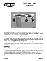
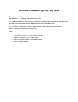
9275 Control Panel
The standard 9275 Filter Control Panel is shipped assembled as shown in Figure
1. The Inlet Elbow Assembly may be rotated up if the water supply is from above.
The Valve must be removed before rotating the assembly.
Figure 1
Key Part No. Description
1 35308 Step Down Regulator and Gauge Kit (shipped un-assembled)
2 9275 Filter Control Panel (shipped assembled)
1
2
MW1504-30 3/99

Chore-Time K-Valve Cage Cup Watering Systems
8
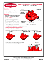
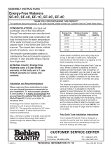
36802-2 Flushable Filter Control Panel
Figure 2
Install Supply Lines from the Control Panel to
Manifolds
Install the incoming water line from the control panel to the cage manifold.Water
can be supplied from above or below. 3/4" PVC pipe, ells, and couplers are
supplied to run a supply line to each manifold.
At least the first section of water line should be installed for each cage line before
installing the Cage Manifold.
Failure to use Pipe Cutters to cut pipes will void the warranty!
Cage Manifold Installation
The water supply line, pipes, couplers, gauges, etc. located at the inlet end of the
cage row are referred to as the cage manifold.
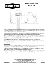
K-Valve installations: Figure 3 shows the recommended cage manifold assembly
and installation for systems up to 600 ft. (183 m). For systems over 600ft (183 m),
refer to Figure 4.
IMPORTANT: No more than two cage tiers per Pressure Regulator. Make
sure the Pressure Regulator is mounted high on the upper tier of the two cage
tiers that it is to regulate. For cage rows over 600 feet long use one regulator
per tier.
The water supply line is commonly located near the center of the cage bank. The
manifold may be installed directly against the end of the cage bank if it does not
interfere with the Dropping Board Scrapers, End Framing, etc. Some installations
may require the cage manifold being installed several inches (75 mm) from the end
of the cages.
Key Part No. Description
1 35308 Step Down Regulator and Gauge Kit (shipped un-assembled)
2 36802-2 Flushable Filter Control Panel (shipped assembled)
MW1504-31 3/99
2
1

Chore-Time K-Valve Cage Cup Watering Systems
9
Follow the instructions for safe use and handling of PVC cement and dry fit all parts before
cementing.
NOTE: A 3/4” Ball Valve, see Figure 3, must be installed in the supply line from filter control
panel BEFORE any cage lines are supplied with water. This valve will enable the water supply to
be shut off for an entire cage row. If optional gauges are to be used on each line, install as shown.
A pressure gauge is supplied with each Regulator Assembly. Locate the gauge and position it on
the top line of the two tiers being regulated (under 600 feet cage row length) where it can be read
conveniently.
NOTE: The manifold kit includes valves for use at the far end of the waterer lines. These allow
individual lines to be flushed or drained. These valves are to be installed after the waterer lines are
installed.
IMPORTANT: A Lever Handle Valve MUST be installed below each pressure gauge, see
Figure 3. Close Lever Handle Valve during high-pressure flushing. Any water pressure
above 15 psi applied to gauge will destroy the gauge.
Figure 3
Key Description Part No.
1 Low Pressure Water Gauge 27722
2 Lever Handle Valve 30137
3 3/4” x 1/4” Reducer Bushing 7789
4 3/4” x 1/2” PVC Ell 8074
5 3/4” PVC Pipe
6 Cage Bank
7 3/4” Ball Valve 34728
8 3/4” PVC Ell 8141
9 K-Valve Inlet Assembly 30135
10 3/4” PVC Street Ell 30138
11 1/2” x 3/4” PVC Ell 8074
12 1/2” PVC Pipe
13 1/2” Ball Valve 9254
14 Bottom Tier
15 Middle Tier
6
7
5
4
3
2
1
5
8
MW1504-28 3/99
12
11
13
14
15
5
9
10

10
Chore-Time K-Valve Cage Cup Watering Systems
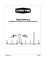
Cage rows over 600’ (183 m)
For cage rows over 600’ in length, install the manifold components as shown in Figure 4.
Notice the 3/4" supply line supplies the entire cage row, but water pressure is controlled by an
Inlet Assembly which supplies a maximum of one tier. A 3/4” Tee must be located after the Inlet
Assembly to supply both sides of each tier. Install a 1/2” Ball Valve on each water line.
Figure 4
Component Spacing Diagrams
Begin at the Manifold end of the cage row. DO NOT INCLUDE THE CONNECTION AT
THE MANIFOLD WHEN COUNTING PIPE JOINTS.
Key Description Part No.
1 Low Pressure Water Gauge 27722
2 Lever Handle Valve 30137
3 3/4” x 1/4” Reducer Bushing 7789
4 3/4” x 1/2” PVC Ell 8074
5 3/4” PVC Pipe
6 Cage Bank
7 3/4” Ball Valve 34728
8 3/4” PVC Ell 8141
9 3/4” PVC Cap 8050
10 K-Valve Inlet Assembly 30135
11 3/4” PVC Street Ell 30138
12 1/2” x 3/4” PVC Ell 8074
13 1/2” PVC Pipe
14 1/2” Ball Valve 9254
15 Bottom Tier
16 Middle Tier
Watering System Pipe Coupler Slip Connector Wire Tie
Chore-Time K-Valve
Cup (8’ pipes)
Locate at all pipe joints not
using a Slip Connector
Locate on 48 (14.6 m) foot centers
beginning at the 6
th
pipe joint
Locate at every
other partition
7
6
5
4
5
13
14
15
12
8
16
9
1
2
3
10
11
MW1504-29 3/99

Chore-Time K-Valve Cage Cup Watering Systems
11
Repeat the pattern specified above for the entire length of the cage row (on
each tier).
Waterer Line Installation
Water line locations and specific installation instructions for each watering system
are given in separate sections of this manual.
The following instructions apply to all systems.
Handle PVC waterer line carefully.
1. Distribute waterer lines along each cage row and place in the approximate
location where the line will be installed.
2. Install a coupling, as shown in Figure 5, at the FIRST (5) PIPE JOINTS from
the manifold end of the row.
Apply PVC cement to the outside of the pipe and the inside of the coupling to be joined.
See the directions on page 6 for instructions on proper use of PVC cement.
BE SURE THE PIPE SECTIONS ARE JOINED SO THAT THE HOSE BARBS ARE
ALL ORIENTED PROPERLY AND POINT IN THE SAME DIRECTION.
Figure 5
3. Install a slip connector, as shown in Figure 6, at the SIXTH PIPE JOINT. The
slip end of the connector should be closest to the manifold end of the house.
Glue the coupling to the water line coming from the manifold end. See directions on
page 6 for instructions for proper use of PVC cement.
Make sure that the indicator line on the Slip Connector is aligned with the edge of the
cap on the Slip Connector, as shown in Figure 6.
Align the next section of pipe and cut off to proper length as shown in Figure 6.
Glue the end of the pipe in the reducing fitting on the end of the Slip Connector.
K-VALVE CUP INSTALLATION: A slip connector should be located every 48 feet
(14.6 m).
4. Repeat steps 2 and 3 the entire length of the cage row.
5. Beginning at the manifold end of the cage row, use a nylon tie at every other
cage partition. Nylon ties should be spaced every 30" (76.2 cm) for 15" cages,
32” (81.3 cm) for 16” cages, or 48" (121.9 cm) for 12” and 24" cages.
NOTE: Do not exceed 48" (121.9 cm) spacing between nylon ties.
Key Description
1 Coupling
2 Pipe Sections
2
1
2
MW1504-7 4/97

Chore-Time K-Valve Cage Cup Watering Systems
12
Figure 6
Outlet Drain Installation
The Manifold Kit contains an outlet valve for each cage waterer line. This is used
when flushing or draining lines during required maintenance of the system.
At the far end of the cage house--opposite the control panel and manifold end--
install an outlet valve on each waterer line. Use the adapter supplied to install the
3/4" drain valve on the 1/2" PVC pipe as shown in Figure 7.
NOTE: Do not install the drain OVER, or IN FRONT OF, the cages.
Figure 7
Key Description
1 Coupling
2 Water Flow
3 Indicator Line
4 Reducing Fitting
5 Cut Pipe Section Here
Key Description
1 End of Water Line
2 Adapter
3 Drain Valve
MW1504-8 7/97
1
2
3
5
4
MW1504-9 4/97
1
2
3

Chore-Time K-Valve Cage Cup Watering Systems
13
Installation of the CHORE-TIME K-Valve Cup
Chore-Time K-Valve Cup (No Spout)
Figure 8
The Chore-Time K-Valve Cup System uses flexible hose to connect the K-Valve
Cup to the waterer line. This allows the Chore-Time K-Valve Cup to be used with
a variety of cage systems. The watering system is available with waterer lines that
have hose barb saddle assemblies at spacings corresponding to various cage
widths. Cups may be placed at every partition or at every other partition.
The cups must be located at recommended locations in the cage. It is very
important that the cups are located out of direct exposure to falling manure and
away from the feeder trough.
Several hose lengths are available to allow the cups to be positioned as needed.
Cups are available with and without spouts. Cups with spouts are available to help
direct water away from the feeder trough.
Consult your Chore-Time Cage Distributor for recommended cup locations for
your system.
Water Line Location
The waterer lines should be installed on top of the cages, in front of the cage legs.
The water line should be located to prevent manure build-up on the pipes.
Note: Waterer line must be located so that the hose can be properly routed when
the cups are installed.
Key Description
1 Cup
2 K-Valve
3 Clamp
4 Tubing
MW1504-3 7/97
2
3
4
1

Chore-Time K-Valve Cage Cup Watering Systems
14
Cup Installation
Refer to the Cage Notching Instructions to determine the exact cup locations.
1. Place the Cup and Hose Assembly into the cage partition opening as shown in
Figure 9. Snap the cup into place as shown in Figure 10. If the cup has a
spout, it must direct water away from the feed trough.
2. Thread the hose through the partition as shown in Figure11. This will prevent
the birds from stepping on or getting caught in the hoses.
DO NOT KINK THE HOSE.
Figure 11
Key Description
1 Thread Hose Through Partition
MW1504-17 8/97
CAGE FRONT
CAGE FRONT
MW1504-18 8/97
Figure 9 Figure 10
MW1504-5 8/97
1

Chore-Time K-Valve Cage Cup Watering Systems
15
3. Slide the end of the hose over the hose barb on the pipe and secure with the
hose clamp. See Figure 12.
Figure 12
In cold weather the cup and tubing assembly must be kept warm until they are
installed or the tubing may have to be warmed to enable the hose to slide over the
barb.
Key Description
1 Hose Barb
2 Hose Clamp
3 Hose
4 Slide hose onto the barb, liquid soap will
help the hose slide easier on barb
5 Slide hose clamp into place, position
midway on hose barb
1
3
2
MW1504-10 4/97
4
5

Chore-Time K-Valve Cage Cup Watering Systems
16
Before Turning On The Water . . . . . . .
Post Installation Check List
-clean all dirt out of cups,
-flush all lines at maximum pressure (1 min per 100’ of cage row length) to remove all
air and any foreign objects that may be inside the system from the installation (be
sure lever handle valve is closed to protect pressure gauge),
-be sure filters are installed correctly and contain a filter cartridge,
-make sure that the cups are fastened to the partitions properly,
After turning on the water
-make sure regulators are set to proper pressures
-check for any leaking or dripping pipe connections,
-check valves,
-maintain house temperature above freezing

Chore-Time K-Valve Cage Cup Watering Systems
17
Recommendations and Guidelines for
Operation
The Chore-Time Cage Watering System requires a minimum incoming water
pressure of 40 p.s.i. (275 kPa) to the control panel. THIS IS THE MINIMUM
ALLOWABLE WATER PRESSURE. Recommended pressure is 40 to 60 p.s.i.
(275 kPa to 413 kPa).
For best operation, maintain water pressure at 1.5 to 2.0 p.s.i. (10.3-13.8 kPa).
Check the pressure gauge at the manifold to see that this pressure is achieved at the
cage bank. Elevation differences between the two locations may require
adjustment of the control panel pressure setting to achieve the desired pressure at
the cage waterer lines.
Water Quality
Water quality is very important for proper operation of the system. Consider the
following:
HARDNESS (Calcium and Magnesium) above 14 GPG (grains per gallon) a water
softener should be used.
PH under 6.5 a neutralizing filter is recommended.
IRON above 0.5 ppm (parts per million) should be treated with a water softener, a
mechanical filtration system, or chlorination, depending on raw water hardness.
Precautions
1. Do not over chlorinate. The maximum concentration is 2 ppm for extended
periods and 5 ppm for flushing only. Do not chlorinate 2 days before or after
medication is used.
To Chlorinate: Mix a stock solution of 3/4 ounces of household chlorine bleach (5.25%
Sodium Hypochlorite) per gallon of water or 5.9 ml of bleach per liter of water. Set the
proportioned to dispense at a rate of one ounce per gallon or 7.8 ml per liter.
2. Some vitamins and medication are syrup type liquids or are sugar based. Avoid
these types of compounds. These compounds may leave a slimy deposit on the
valve seals preventing them from sealing properly. Flush line at high pressure
(incoming line pressure) to remove deposits.
3. Some pumps and/or special purpose gas injectors may add excessive air to the
water supply. For proper operation of the system in these cases, an Air
Remover Kit is recommended to remove the excessive air from the system.
Contact your local Chore-Time distributor.
FAILURE TO FOLLOW THESE PRECAUTIONS WILL VOID THE WARRANTY
ON THE CHORE-TIME WATERING SYSTEM.

Chore-Time K-Valve Cage Cup Watering Systems
18
Cage Watering System Maintenance
General Maintenance
Chore-Time Cage Watering System components require very little maintenance;
the various components are designed and molded from chemical resistant plastic
compounds to provide maximum service with minimal maintenance. Routine
maintenance, however, will help guarantee good service and prolong the life of the
equipment.
When the system is new, monitor water pressure closely. This will be helpful in
determining whether dirt particles, sand, or other particles are present in the water
supply. It will also help determine frequency of filter cartridge cleaning and/or
replacement.
Check the water filter periodically and clean as necessary. Use the pressure gauges
on the control panel as guidelines. When the pressure drops across the filter, it’s
time to clean or replace the filter cartridge. It’s a good idea to keep an extra filter
cartridge on hand.
Chore-Time recommends a 20 micron cartridge. Replacement cartridges for the
9275 Filter Control Panel are available from Chore-Time under part number 7723.
Replacement cartridges for the 36802-2 Flushable Filter Control Panel are
available from Chore-Time under part number 36806.
While in operation, flush the water system thoroughly every 4 weeks (minimum)
to remove algae or trash that builds up in the lines.
NOTE: THIS IS MINIMUM! Some installations may require more frequent
maintenance.
If algae growth becomes a problem, Chore-Time recommends use of a bleach
solution. See "Recommendations and Guidelines" for additional details.
For additional information, see the “Operator’s Troubleshooting Guide" in this
manual.
Maintenance Between Flocks
Flush all air out of the lines.
Flush each line at full pressure for approximately 1 minute per 100’ of cage row
length to remove deposits and sediments.
Check pressure drop across water filter and clean or replace if necessary.
Check pressure gauges, regulators, and shut off valves for proper operation.
Maintain house temperatures above freezing between flocks.
It is strongly recommended that the water remains on between flocks.

Chore-Time K-Valve Cage Cup Watering Systems
19
Chore-Time K-Valve Components
Chore-Time does not recommend servicing K-Valve Assemblies due to potential
damage to components during disassembly and reassembly.
Chore-Time recommends replacing any malfunctioning K-Valve that cannot be
corrected by flushing the lines or triggering the K-Valve.
Figure 13
Important: Installation seating torque is 15 in. lbs. (38 cm. kg). Use only
enough pressure to seat the Valve Body shoulder firmly against the bottom of
the cup. DO NOT overtighten the K-Valves when installing into the cups!
Overtightening may result in damage to the valve body or the cup.
Figure 14
Key Description
1 Deflector
2 Valve Pin
3 Valve Sleeve
4 K-Valve Body
5 Spring
6 Retaining Washer
5
6
MW1504-11 4/97
2
4
3
1
MW1504-12 8/97

Chore-Time K-Valve Cage Cup Watering Systems
20
Parts Listing
9275 Water Filter Control Panel
*These items may be ordered as an assembly under Part Number 9275.
**These items may be ordered as an assembly under Part Number 35803.
Key Description Part No.
1* 3/4" PP Valve 36720
2* Filter Inlet Assembly 35306
3* Water Filter 35309
4* High Pressure Water Gauge 7718
5* Filter Mounting Bracket 35302
6* Filter Outlet Assembly 35304
7* Medicator Outlet Assembly 35305
8* Standoff Block 35300
9* 3/4" Plastic Conduit Clamp 35301
10* 3/4" Nylon Adapter 7543
11* Medicator Connector Brace 35307
12* Filter Cartridge 7723
13* 3/4" PVC Male Adapter 9229
14** Regulator 29951
15** High Pressure Water Gauge 7718
16** 3/4 x 1/4 Reducer Bushing 7789
17** 3/4” PVC Tee 7538
18** 3/4” Threaded PVC Nipple 7531-1
19** 3/4” PVC Street Ell 30138
--* Union 8137
MW1504-23 9/97
15
14
17
16
10
19
18
3
12
13
1
2
4
3
5
4
6
1011
1
1
8
1
7
9
/