Page is loading ...

Vike Aviary System Watering
Installation and Operators Instruction Manual
For additional parts and information, contact your nearest Chore-Time distributor or representative.
Find your nearest distributor at: www.choretime.com/contacts
MW2480AMarch 2019
Installation and Operators Manual
Installation and Operators Manual

Contents
Topic Page
MW2480A
2
Chore-Time Limited Warranty. . . . . . . . . . . . . . . . . . . . . . . . . . . . . . . . . . . . . . . . . . . . . . . . . . . . . 3
Safety Information . . . . . . . . . . . . . . . . . . . . . . . . . . . . . . . . . . . . . . . . . . . . . . . . . . . . . . . . . . . . . . . 4
Follow Safety Instructions . . . . . . . . . . . . . . . . . . . . . . . . . . . . . . . . . . . . . . . . . . . . . . . . . . . . . . . . . . . . . . 4
Decal Descriptions . . . . . . . . . . . . . . . . . . . . . . . . . . . . . . . . . . . . . . . . . . . . . . . . . . . . . . . . . . . . . . . . . . . . 4
DANGER : Moving Auger . . . . . . . . . . . . . . . . . . . . . . . . . . . . . . . . . . . . . . . . . . . . . . . . . . . . . . . . . . 4
DANGER: Electrical Hazard . . . . . . . . . . . . . . . . . . . . . . . . . . . . . . . . . . . . . . . . . . . . . . . . . . . . . . . . 4
Introduction. . . . . . . . . . . . . . . . . . . . . . . . . . . . . . . . . . . . . . . . . . . . . . . . . . . . . . . . . . . . . . . . . . . . . 5
Filtration . . . . . . . . . . . . . . . . . . . . . . . . . . . . . . . . . . . . . . . . . . . . . . . . . . . . . . . . . . . . . . . . . . . . . . . . . . . . 5
Incoming Pressure. . . . . . . . . . . . . . . . . . . . . . . . . . . . . . . . . . . . . . . . . . . . . . . . . . . . . . . . . . . . . . . . . . . . . 5
Planning. . . . . . . . . . . . . . . . . . . . . . . . . . . . . . . . . . . . . . . . . . . . . . . . . . . . . . . . . . . . . . . . . . . . . . . . 6
Tools Required . . . . . . . . . . . . . . . . . . . . . . . . . . . . . . . . . . . . . . . . . . . . . . . . . . . . . . . . . . . . . . . . . . 6
Installation. . . . . . . . . . . . . . . . . . . . . . . . . . . . . . . . . . . . . . . . . . . . . . . . . . . . . . . . . . . . . . . . . . . . . . 7
Raise the suspension to a convenient working height.. . . . . . . . . . . . . . . . . . . . . . . . . . . . . . . . . . . 7
Proper Pipe Cutting and use of PVC Cement . . . . . . . . . . . . . . . . . . . . . . . . . . . . . . . . . . . . . . . . . . . . . . . . 7
Lubrication . . . . . . . . . . . . . . . . . . . . . . . . . . . . . . . . . . . . . . . . . . . . . . . . . . . . . . . . . . . . . . . . . . . . . . . . . . 7
Acceptable Lubrication:. . . . . . . . . . . . . . . . . . . . . . . . . . . . . . . . . . . . . . . . . . . . . . . . . . . . . . . . . . . . . 7
Unacceptable Lubrication:. . . . . . . . . . . . . . . . . . . . . . . . . . . . . . . . . . . . . . . . . . . . . . . . . . . . . . . . . . . 7
Water Line Installation . . . . . . . . . . . . . . . . . . . . . . . . . . . . . . . . . . . . . . . . . . . . . . . . . . . . . . . . . . . . . . . . . 8
Bottom Tier Starter Pipe at the Regulator End . . . . . . . . . . . . . . . . . . . . . . . . . . . . . . . . . . . . . . . . . . . 8
Second Tier Starter Pipe at Water Regulator End . . . . . . . . . . . . . . . . . . . . . . . . . . . . . . . . . . . . . . . . . 9
Regulator Installation . . . . . . . . . . . . . . . . . . . . . . . . . . . . . . . . . . . . . . . . . . . . . . . . . . . . . . . . . . . . . . . . . .10
Regulator Support Assembly. . . . . . . . . . . . . . . . . . . . . . . . . . . . . . . . . . . . . . . . . . . . . . . . . . . . . . . . .10
Attaching Regulators . . . . . . . . . . . . . . . . . . . . . . . . . . . . . . . . . . . . . . . . . . . . . . . . . . . . . . . . . . . . . . .10
Plumbing Regulators to Starter Pipe . . . . . . . . . . . . . . . . . . . . . . . . . . . . . . . . . . . . . . . . . . . . . . . . . . .11
Mid-line Stand Tube Installation. . . . . . . . . . . . . . . . . . . . . . . . . . . . . . . . . . . . . . . . . . . . . . . . . . . . . .12
Drain Line (Flush End) Assembly. . . . . . . . . . . . . . . . . . . . . . . . . . . . . . . . . . . . . . . . . . . . . . . . . . . . .13
Bottom Tier Drain Plumbing. . . . . . . . . . . . . . . . . . . . . . . . . . . . . . . . . . . . . . . . . . . . . . . . . . . . . . . . .14
Second Tier Drain Plumbing . . . . . . . . . . . . . . . . . . . . . . . . . . . . . . . . . . . . . . . . . . . . . . . . . . . . . . . . . . . .15
Filter Control Panel Installation . . . . . . . . . . . . . . . . . . . . . . . . . . . . . . . . . . . . . . . . . . . . . . . . . . . 16
Flushable Filter Control Panel Installation . . . . . . . . . . . . . . . . . . . . . . . . . . . . . . . . . . . . . . . . . . 17
Maintenance . . . . . . . . . . . . . . . . . . . . . . . . . . . . . . . . . . . . . . . . . . . . . . . . . . . . . . . . . . . . . . . . . . . 18
Regulator Seat Replacement. . . . . . . . . . . . . . . . . . . . . . . . . . . . . . . . . . . . . . . . . . . . . . . . . . . . . . . . . . . . .18
Parts Listing . . . . . . . . . . . . . . . . . . . . . . . . . . . . . . . . . . . . . . . . . . . . . . . . . . . . . . . . . . . . . . . . . . . 20
Waterline Parts . . . . . . . . . . . . . . . . . . . . . . . . . . . . . . . . . . . . . . . . . . . . . . . . . . . . . . . . . . . . . . . . . . . . . . .20
Water Regulator Kit (54536) . . . . . . . . . . . . . . . . . . . . . . . . . . . . . . . . . . . . . . . . . . . . . . . . . . . . . . . . . . . .23
Filter Control Panel with Step Regulator . . . . . . . . . . . . . . . . . . . . . . . . . . . . . . . . . . . . . . . . . . . . . . .24
Flush able Filter Control Panel (36802-1 and 36802-2) . . . . . . . . . . . . . . . . . . . . . . . . . . . . . . . . . . . .25
Pulse Water Meter (54579) . . . . . . . . . . . . . . . . . . . . . . . . . . . . . . . . . . . . . . . . . . . . . . . . . . . . . . . . . .26
Slope Compensator (54035) . . . . . . . . . . . . . . . . . . . . . . . . . . . . . . . . . . . . . . . . . . . . . . . . . . . . . . . . .26
Regulator Assembly (55476-4, and 55476-5) . . . . . . . . . . . . . . . . . . . . . . . . . . . . . . . . . . . . . . . . . . . .28
Misc. Components List . . . . . . . . . . . . . . . . . . . . . . . . . . . . . . . . . . . . . . . . . . . . . . . . . . . . . . . . . . . . .31

Vike Aviary System Watering Chore-Time Limited Warranty
3
MW2480A
Chore-Time Group, a division of CTB, Inc. (“Chore-Time”) warrants the new CHORE-TIME Watering products
manufactured by Chore-Time to be free from defects in material or workmanship under normal usage and conditions, for One
(1) year from the date of installation by the original purchaser (“Warranty”). Chore-Time provides for an extension of the
aforementioned Warranty period (“Extended Warranty Period”) with respect to certain Product parts (“Component Part”) as
set forth in the table below. If such a defect is determined by Chore-Time to exist within the applicable period, Chore-Time
will, at its option, (a) repair the Product or Component Part free of charge, F.O.B. the factory of manufacture or (b) replace the
Product or Component Part free of charge, F.O.B. the factory of manufacture. This Warranty is not transferable, and applies
only to the original purchaser of the Product.
CONDITIONS AND LIMITATIONS
THIS WARRANTY CONSTITUTES CHORE-TIME’S ENTIRE AND SOLE WARRANTY AND CHORE-TIME
EXPRESSLY DISCLAIMS ANY AND ALL OTHER WARRANTIES, INCLUDING, BUT NOT LIMITED TO, EXPRESS
AND IMPLIED WARRANTIES, INCLUDING, WIHTOUT LIMITATION, WARRANTIES AS TO MERCHANTABILITY
OR FITNESS FOR PARTICULAR PURPOSES. CHORE-TIME shall not be liable for any direct, indirect, incidental,
consequential or special damages which any purchaser may suffer or claim to suffer as a result of any defect in the Product.
Consequential or Special Damages as used herein include, but are not limited to, lost or damaged products or goods, costs of
transportation, lost sales, lost orders, lost income, increased overhead, labor and incidental costs, and operational
inefficiencies. Some jurisdictions prohibit limitations on implied warranties and/or the exclusion or limitation of such
damages, so these limitations and exclusions may not apply to you. This warranty gives the original purchaser specific legal
rights. You may also have other rights based upon your specific jurisdiction.
Compliance with federal, state and local rules which apply to the location, installation and use of the Product are the
responsibility of the original purchaser, and CHORE-TIME shall not be liable for any damages which may result from non-
compliance with such rules.
The following circumstances shall render this Warranty void:
• Modifications made to the Product not specifically delineated in the Product manual.
• Product not installed and/or operated in accordance with the instructions published by the CHORE-TIME.
• All components of the Product are not original equipment supplied by CHORE-TIME.
• Product was not purchased from and/or installed by a CHORE-TIME authorized distributor or certified representative.
• Product experienced malfunction or failure resulting from misuse, abuse, mismanagement, negligence, alteration, acci-
dent, or lack of proper maintenance, or from lightning strikes, electrical power surges or interruption of electricity.
• Product experienced corrosion, material deterioration and/or equipment malfunction caused by or consistent with the
application of chemicals, minerals, sediments or other foreign elements.
• Product was used for any purpose other than for the care of poultry and livestock.
The Warranty and Extended Warranty may only be modified in writing by an officer of CHORE-TIME. CHORE-TIME shall
have no obligation or responsibility for any representations or warranties made by or on behalf of any distributor, dealer, agent
or certified representative.
Effective: April, 2014
Chore-Time Limited Warranty
Component Part Extended Warranty Period
RXL Fan (except motors and bearings)
Three (3) Years
TURBO® Fan (except motors and bearings) Three (3) Years
TURBO® Fan fiberglass housing, polyethylene cone, and cast aluminum blade. Lifetime of Product
TURBO® fan motor and bearings. Two (2) Years
Chore-Time® Poultry Feeder Pan Three (3) Years
Chore-Time® Rotating Centerless Augers (except where used in applications involving high
moisture feed stuffs exceeding 17%)
Ten (10) Years
Chore-Time Steel Auger Tubes Ten (10) Years
ULTRAFLO® Breeder Feeding System auger and feed trough. Five (5) Years
ULTRAPAN® Feeding System augers. Five (5) Years

Safety Information Vike Aviary System Watering
4
MW2480A
Caution, Warning and Danger Decals have been placed on the equipment to warn of potentially dangerous
situations. Care should be taken to keep this information intact and easy to read at all times. Replace missing or
damaged safety decals immediately.
Safety–Alert Symbol
This is a safety–alert symbol. When you see this symbol on your equipment, be alert to the potential
for personal injury. This equipment is designed to be installed and operated as safely as
possible...however, hazards do exist.
Understanding Signal Words
Signal words are used in conjunction with the safety–alert symbol to identify the severity of the warning.
DANGER indicates an imminently hazardous situation which, if not avoided, WILL result in death or
serious injury.
WARNING indicates a potentially hazardous situation which, if not avoided, COULD result in death or
serious injury.
CAUTION indicates a hazardous situation which, if not avoided, MAY result in minor or moderate
injury.
Follow Safety Instructions
Carefully read all safety messages in this manual and on your equipment safety signs. Follow recommended
precautions and safe operating practices.
Keep safety signs in good condition. Replace missing or damaged safety signs.
Decal Descriptions
DANGER : Moving Auger
This decal is placed on the End Cap Weldment and Clean-out
cover. Severe personal injury will result, if the electrical
power is not disconnected, prior to servicing the equipment.
DANGER: Electrical Hazard
Disconnect electrical power before inspecting or servicing equipment unless
maintenance instructions specifically state otherwise.
Ground all electrical equipment for safety.
All electrical wiring must be done by a qualified electrician in accordance with
local and national electric codes.
Ground all non-current carrying metal parts to guard against electrical shock.
Electrical disconnects and over current protection are not supplied with the
equipment.
Safety Information

Vike Aviary System Watering Introduction
5
MW2480A
Filtration
Good water quality maximizes performance of the equipment, minimizes maintenance and repair, and increases
the life of the system.
Pump the well prior to hookup of the system to clear sand, mud, or debris. CHORE-TIME recommends a water
test by a reputable water treatment company in the area. Water treatment and/or extra filtration may be required,
depending on the water test results.
A minimum of 1, 140 mesh filter is recommended. For systems with high sand/silt levels a secondary, more
aggressive, filter should be placed down stream of the 140 mesh filter.
Incoming Pressure
CHORE-TIME recommends a minimum incoming water pressure of 3 psi [21 kPa] for gravity feed systems. To
obtain this minimum pressure the water level in the water tank should be maintained 8’ [2.4 m] above the nipple
line. CHORE-TIME recommends a Maximum line length of 250’ [76 m] for a gravity feed system.
For every 28" [711 mm] of water column, water pressure increases one pound. Measure the operating pressure at
bottom of the water pipe.
Incoming water supply should be at least a 1" [25 mm] diameter incoming line (preferably PVC) from a single
well. If there are two or more supply wells, the supply line should be larger. Other factors such as, the distance
from the well(s) to the filter control panel and other equipment which requires water could demand larger lines.
Each pressure regulator is capable of supplying one tier (two lines) up to 600 feet (182.8 meters). Systems over
600 feet (182.8 meters) require two inlet assemblies per tier (one per line).
Introduction
Filter Control Panels Regulators
Part Number 36802-1 9275/36802-2 All
Incoming Pressure 3-11 psi 11-35 psi* 3-35 psi
For incoming pressure between 35 and 125 psi use the 35308
pressure step down assembly with the filter control panel.

Planning Vike Aviary System Watering
6
MW2480A
Chore-Time recommends taking time to lay out the sections of water pipe and other large components prior to
beginning each installation step. Hardware, tools, and small components (valves, etc.) may be conveniently
carried in a carpenter’s apron.
It may speed up installation, if you assemble sub-assemblies prior to the nipple water installation. Assembly
instructions are included in this manual for the stand tube sub-assemblies.
Installation of Chore-Time Cage Watering System can be broken down into the following general steps:
•Installation of the water lines and accessories.
•Installation of the Regulator.
•Installation of the Stand Tubes.
•Installation of the Drain/Overflow Pipes.
Notes:
1.On the Bottom Tiers only install Watering Lines every other Cage Row.
2.Incoming water line (before Water Regulator) is not supplied.
Tools needed to install your nipple water system include:
Planning
Tools Required
• Regular Screwdriver • Bolt cutters or Hack Saw
• Locking Pliers • PVC Cleaning Solvent
• File • Electric Drill and Drill Bits
• Saw top cut PVC tube • De-Burring tool
• Screw-Hook Driver

Vike Aviary System Watering Installation
7
MW2480A
Raise the suspension to a convenient working height.
Proper Pipe Cutting and use of PVC Cement
FOLLOW THE DIRECTIONS ON THE
CONTAINER OF PVC CEMENT FOR SAFE
HANDLING AND BEST RESULTS.
1.Be sure pipe is cut off squarely. USE PIPE CUTTERS ONLY.
Failure to use pipe cutters voids the warranty.
2.Remove dirt and burrs from outside and inside of the pipe.
3.Dry fit all parts before cementing. Pipe should be fit into fittings
without applying excess force.
4.Surfaces to be joined should be clean--free from dirt, oil, and grease. Use PVC Pipe Cleaner, as needed.
5.Apply PVC cement to both surfaces to be joined. Apply cement sparingly, but evenly over the entire surface,
leave no bare spots.
Lubrication
Acceptable Lubrication:
•Plain water or light dish soap and
water mixture may be used to
lubricate the inside of the coupling, mid
line air breather or slope compensator
assemblies.
•Silicone oil based Parker Super O-
Lube (available through Chore-Time
part number 45911) may be used to
lubricate the inside of the coupling, mid
line air breather or slope compensator
assemblies. Note: Very little (thin film) of this product is needed to provide necessary lubrication.
Unacceptable Lubrication:
•DO NOT use petroleum based Parker O-Lube Product! Only the Parker Silicone oil based Parker Super
O-Lube is acceptable.
•DO NOT
use silicone spray! These may have petroleum based properties that may damage water line
components.
•DO NOT
use any petroleum based product! This would include, but is not limited to, items such as
Vaseline, WD 40, motor oil, ect.
•DO NOT
use vegetable or any other similar oil! This would include, but is not limited to, sunflower oil,
peanut oil, coconut oil, linseed oil, corn oil, ect.
Important!
Use of any lubricant during installation, other than those approved by Chore-Time, will void the
manufactures warranty.
Installation
Figure 1.PVC Cement (Part No. 6303-4)
Important!
Figure 2.Lubrication
Air Breather/Slope
compensator
Coupling
Pipe Assembly

Raise the suspension to a convenient working height. Vike Aviary System Watering
8
MW2480A
Water Line Installation
Note: Only install bottom tier watering lines every other Cage Row.
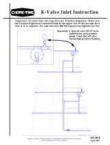
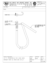
Bottom Tier Starter Pipe at the Regulator End
Figure 3.Bottom Tier Starter Pipe
Item Description
1 Water Pipe Assembly (8 Nipples) 56176-2
2 Locater Block 35706
3 Watering Bottom Bracket 562031
4 5/16-18 x 1/2 Hx WH SFTP Screw 56177
5 Catch Cup 36591
6 Coupling Assembly 35763
8 Nipples
1
Water Regulator End
2
4x
4
3
4x
4
Snap Catch Cups in
place if required.
5
2
Locater Block Centered
4x
4
Locater Block Centered
3
6
3
(56177)
5/16-18x1/2 Screw
Full Scale
Triangular
Top

Vike Aviary System Watering Raise the suspension to a convenient working height.
9
MW2480A
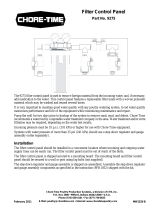
Second Tier Starter Pipe at Water Regulator End
Figure 4.Starter Pipe (Second Tier)
Center Locater Block
on Watering Bracket
Item Description Part No.
1 Water Pipe Assembly (12 Nipples) 56176-1
2 Locater Block 35706
3 Watering Hanger 56175
4 Watering Pipe Wire Clip 56277
5 5/16-18 x 1/2 Hx WH SFTP Screw 56177
6 Coupling Assembly 35763
12 Nipples
1
Water Inlet End
2
5
Snap Catch Cups in place
if required.
5
4
5
3
Center of Locater Block
3
Center of Locater Block
4
2
6
(56177)
5/16-18x1/2 Screw
Full Scale
Triangular
Top

Raise the suspension to a convenient working height. Vike Aviary System Watering
10
MW2480A
Regulator Installation
Regulator Support Assembly
Attaching Regulators
Figure 5.Regulator Support Assembly
Item Description Part No.
1 Regulator Assembly 52280-0
2 Regulator Support 54424
3 Regulator Clamp 53862
4 1/4-20 Carriage Bolt 7550-1
5 1/4-20 Flange Nut 46460
3 4
1
5
2
(7550-1)
1/4-20 Car. Bolt
(46460)
1/4-20 Flg. Nut
Hardware Full Scale
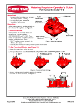
Figure 6.Attaching Regulators
Item Description Part No.
1 Idler Leg 101301
2 1/4-20 x 1 Bolt 2029
3 1/4-20 Ser. Flg. Nut 46460
4 Starter Pipe (Inlet End) Varies
4
Regulators level with or
slightly above Nipple
Water Lines.
3
2
One Regulator per Tier
1
(46460) 1/4-20 Flg. Nut
(2029) 1/4-20 x1.0 Bolt
Hardware Full Scale
1

Vike Aviary System Watering Raise the suspension to a convenient working height.
11
MW2480A
Plumbing Regulators to Starter Pipe
See “Proper Pipe Cutting and use of PVC Cement” on page 7 for proper cutting and gluing instructions.
Item Description
7 3/4" x 1/2" PVC Ell 8074
8 .75-11.5 NH Male Adapter Fitting 25098
9 3/4 Female Swivel Fitting 50401
10 3/4" I.D. Rubber Hose 47820-X
11 3/4" PVC SXSXS Tee 7538
12 3/4" PVC Female Adapter 8160
Item Description
1 Stand Tube Assembly 54517-4
2 Pipe (Cut to length) 8083-10
3 Union 8137
4 .75 PVC ST Ell 30138
5 .75 PVC SxS Ell 8141
6 Adjustable Hose Clamp 7187
5
4
3
2
7
6
6
12
Not required on Bottom Tier
5
11
1
8
10
2
5
2
9
Figure 7.Inlet End Plumbing

Raise the suspension to a convenient working height. Vike Aviary System Watering
12
MW2480A
Mid-line Stand Tube Installation
1.Install Mid-Line Stand Tubes on each Water Line as shown in plumbing diagrams below.
2.Be sure to properly deburr the end of the pipes to prevent damage.
Figure 8.Mid-Line Stand-Tube Installation
Drain End
Inlet (Regulator End)
1
Center Locater Block on Hanger
Item Description
1 Mid-Line Stand Tube Assembly 54517-6
2 3/4" PVC SXSXS Tee 7538
3 3/4" PVC ST Ell 30138
4 Pipe cut to length
Long enough to clear framing
8083-10
5 3/4" PVC SxS Ell 7558
2
3
4
1
Center of Cage Row
(Mid-line)
Bottom Tier
Water Line
Top Tier
Water Line
Cut to length
Stand Tubes slightly offset
Top Tier (Both Sides)
Bottom Tier
Cut to length
Center Locater Block on Hanger
5
3
4
1
2
1
5

Vike Aviary System Watering Raise the suspension to a convenient working height.
13
MW2480A
Drain Line (Flush End) Assembly
Parts are provided for proper draining of the system as shown. See Figure 10. on page 14 & Figure 11. on page
15 for details.
Figure 9.Drain Line (Flush End)
Item Description
1 1.5" x 10’ PVC Pipe 38296
2 1.5" SxSxS PVC Tee 38618
3 1.5" PVC Cross 38295
4 Watering Drain Pipe Plate 56384
5 #10 x 1/2 Self Drilling Screw 3037
6 1.5" Plastic Conduit Clamp 35301-1
7 3/4 PVC Clear Pipe 29153-4
8 1.5" PVC Cap 38498
Stagger Stand Tubes
for easier viewing.
5
1
Level with 1st tier
Nipple Water Line
64
7
Angled to clear Second Tier
Level with 2nd tier
Nipple Water Line
High enough to avoid
Manure Drive Parts.
Top View
Parts shown transparent
so Stand Tube is visible.
2
3
Drill four 1/4" [6mm] Holes in the
1-1/2" Cap (Item8)
8
5
(3037) #10 x 1/2" Screw
Hardware Full Scale

Raise the suspension to a convenient working height. Vike Aviary System Watering
14
MW2480A
Bottom Tier Drain Plumbing
1.See “Proper Pipe Cutting and use of PVC Cement” on page 7 for proper cutting and gluing instructions.
2.Install a Nipple Line End Section (Item 1) with the Locater Block centered on the last Bottom Bracket (Item
2) as shown. Cut the Nipple Line End off and install a Cap (Item 3).
3.Install a 3/4" Clear Pipe (Item 8), 3/4" PVC Union (Item 11) and 3/4" Ball Valve (Item 7) as shown.
Item Description
1 Nipple Line End Section 51796-1
2 Volito
TM
Watering Bottom Bracket 56203
3 3/4" PVC Cap 8050
4 3/4 PVC Pipe (cut to desired length) 8083-10
5 3/4" PVC SXSXS Tee 7538
6 .75 PVC SxS Ell 8141
7 3/4 Ball Valve 34728
8 3/4 PVC Clear Pipe 29153-4
9 1-1/2" PVC Tee 38618
10 Reducer Bushing 36808
11 3/4" PVC SxS Union 8137
6
7
1
Center Locater Block
on Bottom Bracket
2
3
14
13
5
4
11
6
9
10
Figure 10.Bottom Tier Drain Plumbing
8
Cut Wire for clearance

Vike Aviary System Watering Raise the suspension to a convenient working height.
15
MW2480A
Second Tier Drain Plumbing
See “Proper Pipe Cutting and use of PVC Cement” on page 7 for proper cutting and gluing instructions.
1.Install Nipple Line End Sections (Item 1) using Watering Pipe Wire Clips (Item 2) while centering Locater
Blocks on Watering Hangers (Item 4) as shown.
2.Install a 3/4" Ball Valve (Item 5), 3/4" PVC Coupling (Item 10), and 3/4" Clear Pipe (Item 9) for each
Nipple Water Line as shown.
Figure 11.Second Tier Drain Plumbing
5
3
10
6
7
6
7
9
Cut Pipe and
Channel
Center Locater
Block on Bottom
Watering Hanger
1
2
4
Cut Off
Centered
7
10
9
7
Outside View
7
Cut Off
Pipe through
Hole in Drive
Leg.
11
4
1
2
Cut Off
High enough to clear Manure
Drive Components
8
Item Description
1 Nipple Line End Section 51796-1
2 Watering Pipe Wire Clip 56277
3 5/16-18 x 1/2 Hx WH Bolt 56177
4 Watering Hanger 56175
5 3/4 Ball Valve 34728
6 3/4" PVC SXSXS Tee 7538
Item Description
7 .75 PVC SxS Ell 8141
8 Pipe cut to length
Long enough to clear framing
8083-10
9 3/4 PVC Clear Pipe 29153-4
10 3/4" PVC SxS Union 8137
11 3/4" PVC Coupling S x S 7775
(56177)
5/16-18x1/2 Screw
Full Scale

Filter Control Panel Installation Vike Aviary System Watering
16
MW2480A
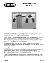
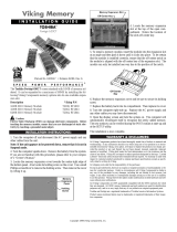
The filter control panel is used to remove foreign material from the incoming water, and, if necessary, add
medication to the water.
The step down regulator and gauge assembly is used to reduce the water pressure supplying the filter control panel.
The filter control panel and step down regulator should be installed in a convenient location where incoming and
outgoing water supply lines can be easily run. The control panel must be out of the reach of birds.
The filter control panel is shipped secured to a mounting board. The mounting board and filter control panel should
be secured to wall or post using lag bolts (not supplied).
The step down regulator and gauge assembly is shipped un-assembled. Assemble the step down regulator and
gauge assembly components as specified in the instruction (MW1052) shipped with the kit.
Connect the step down regulator and gauge assembly to the filter control panel, as shown in Figure 17.
Filter Control Panel Installation
Filter Control Panel
Part Number 9275
Step Down Regulator
and Gauge Kit
Part Number 35308
Figure 12. 9275 Control Panel

Vike Aviary System Watering Flushable Filter Control Panel Installation
17
MW2480A
(Optional alternative to the standard filter control panel)
The flushable filter control panel is used to remove foreign material from the incoming water, and, if necessary,
add medication to the water. This control panel features a filter that may be flushed, removed, cleaned, then
reinstalled.
Two versions of the filter control panel are available.
The low pressure version is designed to accommodate gravity flow systems with 5 - 10 p.s.i [34.5 - 69.0 kPa]. Do
not exceed 15 p.s.i. [103.4 kPa] with this control panel, or damage will occur to the gauges.
Systems with 11+ p.s.i. [75.8+ kPa] should use the high pressure control panel. For systems above 35 psi, order
a step down regulator.
The filter control panel should be installed in a convenient location where incoming and outgoing water supply
lines can be easily run. The control panel must be out of the reach of birds.
The filter control panel is shipped secured to a mounting board. The mounting board and filter control panel should
be secured to wall or post using lag bolts (not supplied).
The gauge assembly is shipped un-assembled. Assemble the gauge assembly components as specified in the
instruction (MW1052) shipped with the kit.
Flushable Filter Control Panel Installation
Low Pressure Control Panel
Part Number 36802-1
(5-10 p.s.i. [34.5 - 69.0 kPa])
High Pressure Control Panel
Part Number 36802-2
(11+ p.s.i. [75.8+ kPa]
Figure 13. Optional Control Panels

Maintenance Vike Aviary System Watering
18
MW2480A
Regulator Seat Replacement
Follow the procedures below to replace the regulator seat.
1.Shut off water to the regulator and remove it from the nipple line.
2.Remove the screw holding the shroud. Also remove the shroud, selector knob,
quad ring, and inlet orifice.
3.Screw barrel all the way down.
4.Pry off seat and seat cup then remove from the regulator body.
5.Assemble new seat into seat cup.
Seat face direction does not matter.
6.Use the Chore-Time seat
installation tool to position the new
seat assembly on top of the seat
holder.
7.Press up on the seat holder and use
the seat installation tool (48688) to
push the new seat assembly onto
the end of the seat holder until it
snaps in place. Push only on the
seat cup to prevent damage to the
seat. Make sure the seat assembly
is properly seated onto the seat
holder.
8.Reassemble the regulator:
•Assemble quad ring on the
housing shoulder. Turn the barrel
up until it is flush with the top of
the housing.The barrel must be
flush with the top before
replacing the selector knob or the
regulator will not function
properly.
•Replace the selector knob by
lining up the wide tab in the
barrel with the wide groove
inside the selector knob.
•Make sure the o-ring is in place
and reinstall the inlet into the
regulator housing.
•Use Parker Hannifin Super o-lube
(45911) to lube o-rings if needed.
•Replace the shroud and shroud
screw.
•The regulator is now ready to be put back into service.
Maintenance
1
Shroud
Selector
Knob
Quad Ring
Inlet
2
3
4
5 6
7
Barrel
Seat
Seat Cup
Seat
(48688)
Shroud
Screw
8
Barrel Wide
Quad
Ring
Barrel
Flush
Tab
Selector
Wide Groove


/