Page is loading ...

ULTRAFLO
®
Cage Feeding Systems
for Brood Grow & Layer Installations
Installation and Operators
Instruction Manual
For additional parts and information, contact your nearest Chore-Time distributor or representative.
Find your nearest distributor at: www.choretime.com/contacts
MC656PNovember 2018
Installation and Operators Manual
Installation and Operators Manual

Limited Warranty ULTRAFLO
®
Cage Feeding Systems for Brood Grow & Layer Installations
2
MC656P
Chore-Time Group, a division of CTB, Inc. (“Chore-Time”) warrants new CHORE-TIME Cage and Cage
Components manufactured by Chore-Time to be free from defects in material or workmanship under
normal usage and conditions, for One (1) year from the date of installation by the original purchaser
(“Warranty”). If such a defect is determined by Chore-Time to exist within the applicable period, Chore-
Time will, at its option, (a) repair the Product or Component Part free of charge, F.O.B. the factory of
manufacture or (b) replace the Product or Component Part free of charge, F.O.B. the factory of
manufacture. This Warranty is not transferable, and applies only to the original purchaser of the Product.
CONDITIONS AND LIMITATIONS
THIS WARRANTY CONSTITUTES CHORE-TIME’S ENTIRE AND SOLE WARRANTY AND
CHORE-TIME EXPRESSLY DISCLAIMS ANY AND ALL OTHER WARRANTIES, INCLUDING,
BUT NOT LIMITED TO, EXPRESS AND IMPLIED WARRANTIES, INCLUDING, WITHOUT
LIMITATION, WARRANTIES AS TO MERCHANTABILITY OR FITNESS FOR PARTICULAR
PURPOSES. CHORE-TIME shall not be liable for any direct, indirect, incidental, consequential or
special damages which any purchaser may suffer or claim to suffer as a result of any defect in the Product.
Consequential or Special Damages as used herein include, but are not limited to, lost or damaged products
or goods, costs of transportation, lost sales, lost orders, lost income, increased overhead, labor and
incidental costs, and operational inefficiencies. Some jurisdictions prohibit limitations on implied
warranties and/or the exclusion or limitation of such damages, so these limitations and exclusions may
not apply to you. This warranty gives the original purchaser specific legal rights. You may also have other
rights based upon your specific jurisdiction.
Compliance with federal, state and local rules which apply to the location, installation and use of the
Product are the responsibility of the original purchaser, and CHORE-TIME shall not be liable for any
damages which may result from non-compliance with such rules.
The following circumstances shall render this Warranty void:
· Modifications made to the Product not specifically delineated in the Product manual.
· Product not installed and/or operated in accordance with the instructions published by the
CHORE-TIME.
· All components of the Product are not original equipment supplied by CHORE-TIME.
· Product was not purchased from and/or installed by a CHORE-TIME authorized distributor or
certified representative.
· Product experienced malfunction or failure resulting from misuse, abuse, mismanagement,
negligence, alteration, accident, or lack of proper maintenance, or from lightning strikes,
electrical power surges or interruption of electricity.
· Product experienced corrosion, material deterioration and/or equipment malfunction caused by
or consistent with the application of chemicals, minerals, sediments or other foreign elements.
· Product was used for any purpose other than for the care of poultry and livestock.
The Warranty and Extended Warranty may only be modified in writing by an officer of CHORE-TIME.
CHORE-TIME shall have no obligation or responsibility for any representations or warranties made by or
on behalf of any distributor, dealer, agent or certified representative.
Effective: April, 2014
Limited Warranty

Contents
Topic Page
MC656P
3
Limited Warranty. . . . . . . . . . . . . . . . . . . . . . . . . . . . . . . . . . . . . . . . . . . . . . . . . . . . . . . . . . . . . . . . 2
Safety and General Information . . . . . . . . . . . . . . . . . . . . . . . . . . . . . . . . . . . . . . . . . . . . . . . . . . . . 5
Follow Safety Instructions . . . . . . . . . . . . . . . . . . . . . . . . . . . . . . . . . . . . . . . . . . . . . . . . . . . . . . . . . . . . . . 5
Decal Descriptions . . . . . . . . . . . . . . . . . . . . . . . . . . . . . . . . . . . . . . . . . . . . . . . . . . . . . . . . . . . . . . . . . . . . 5
DANGER: Moving Auger. . . . . . . . . . . . . . . . . . . . . . . . . . . . . . . . . . . . . . . . . . . . . . . . . . . . . . . . . . . 5
DANGER: Electrical Hazard . . . . . . . . . . . . . . . . . . . . . . . . . . . . . . . . . . . . . . . . . . . . . . . . . . . . . . . . 5
Planning the Installation . . . . . . . . . . . . . . . . . . . . . . . . . . . . . . . . . . . . . . . . . . . . . . . . . . . . . . . . . . 6
Power Unit Requirements. . . . . . . . . . . . . . . . . . . . . . . . . . . . . . . . . . . . . . . . . . . . . . . . . . . . . . . . . . . . . . . 6
Hanger Requirements . . . . . . . . . . . . . . . . . . . . . . . . . . . . . . . . . . . . . . . . . . . . . . . . . . . . . . . . . . . . . . . . . . 6
Additional Manuals. . . . . . . . . . . . . . . . . . . . . . . . . . . . . . . . . . . . . . . . . . . . . . . . . . . . . . . . . . . . . . . . . . . . 6
ULTRAFLO® Hanger Chart . . . . . . . . . . . . . . . . . . . . . . . . . . . . . . . . . . . . . . . . . . . . . . . . . . . . . . . . . . . . 7
Installation for Brood-Grow Cage Systems Only . . . . . . . . . . . . . . . . . . . . . . . . . . . . . . . . . . . . . . 8
Power Unit Location. . . . . . . . . . . . . . . . . . . . . . . . . . . . . . . . . . . . . . . . . . . . . . . . . . . . . . . . . . . . . . . . . . . 8
Single Power Unit System. . . . . . . . . . . . . . . . . . . . . . . . . . . . . . . . . . . . . . . . . . . . . . . . . . . . . . . . . . . 8
Two Power Unit System . . . . . . . . . . . . . . . . . . . . . . . . . . . . . . . . . . . . . . . . . . . . . . . . . . . . . . . . . . . . 8
Three Power Unit System . . . . . . . . . . . . . . . . . . . . . . . . . . . . . . . . . . . . . . . . . . . . . . . . . . . . . . . . . . . 9
Four Power Unit Assembly . . . . . . . . . . . . . . . . . . . . . . . . . . . . . . . . . . . . . . . . . . . . . . . . . . . . . . . . . . 9
Trough Installation . . . . . . . . . . . . . . . . . . . . . . . . . . . . . . . . . . . . . . . . . . . . . . . . . . . . . . . . . . . . . . . . . . . .10
Trough Support . . . . . . . . . . . . . . . . . . . . . . . . . . . . . . . . . . . . . . . . . . . . . . . . . . . . . . . . . . . . . . . . . . .10
Trough . . . . . . . . . . . . . . . . . . . . . . . . . . . . . . . . . . . . . . . . . . . . . . . . . . . . . . . . . . . . . . . . . . . . . . . . . .11
Trough Installation (continued) . . . . . . . . . . . . . . . . . . . . . . . . . . . . . . . . . . . . . . . . . . . . . . . . . . . . . . . . . .13
Installation for Layer Cage Systems Only . . . . . . . . . . . . . . . . . . . . . . . . . . . . . . . . . . . . . . . . . . . 14
Power Unit Location. . . . . . . . . . . . . . . . . . . . . . . . . . . . . . . . . . . . . . . . . . . . . . . . . . . . . . . . . . . . . . . . . . .14
Single Power Unit System. . . . . . . . . . . . . . . . . . . . . . . . . . . . . . . . . . . . . . . . . . . . . . . . . . . . . . . . . . .14
Two Power Unit System . . . . . . . . . . . . . . . . . . . . . . . . . . . . . . . . . . . . . . . . . . . . . . . . . . . . . . . . . . . .14
Three Power Unit System . . . . . . . . . . . . . . . . . . . . . . . . . . . . . . . . . . . . . . . . . . . . . . . . . . . . . . . . . . .15
Four Power Unit System . . . . . . . . . . . . . . . . . . . . . . . . . . . . . . . . . . . . . . . . . . . . . . . . . . . . . . . . . . . .15
Trough Installation . . . . . . . . . . . . . . . . . . . . . . . . . . . . . . . . . . . . . . . . . . . . . . . . . . . . . . . . . . . . . . . . . . . .16
Trough Hangers . . . . . . . . . . . . . . . . . . . . . . . . . . . . . . . . . . . . . . . . . . . . . . . . . . . . . . . . . . . . . . . . . . .16
Trough . . . . . . . . . . . . . . . . . . . . . . . . . . . . . . . . . . . . . . . . . . . . . . . . . . . . . . . . . . . . . . . . . . . . . . . . . .17
Retainer Wire Installation (for SSS & ST-2 Only) . . . . . . . . . . . . . . . . . . . . . . . . . . . . . . . . . . . . . . . .19
Trough Clip and Wire Installation (for DURATM Systems Only). . . . . . . . . . . . . . . . . . . . . . . . . . . .19
MMB® Trough Hanger and Trough Installation . . . . . . . . . . . . . . . . . . . . . . . . . . . . . . . . . . . . . . . . .20
Versa Plus Trough Hanger and Trough Installation . . . . . . . . . . . . . . . . . . . . . . . . . . . . . . . . . . . . . . .21
Versa Trough Hanger and Trough Installation . . . . . . . . . . . . . . . . . . . . . . . . . . . . . . . . . . . . . . . . . . .21
Power Unit Installation . . . . . . . . . . . . . . . . . . . . . . . . . . . . . . . . . . . . . . . . . . . . . . . . . . . . . . . . . . . . . . . . .23
End Components Installation . . . . . . . . . . . . . . . . . . . . . . . . . . . . . . . . . . . . . . . . . . . . . . . . . . . . . . . . . . . .25
Intake Cup Installation. . . . . . . . . . . . . . . . . . . . . . . . . . . . . . . . . . . . . . . . . . . . . . . . . . . . . . . . . . . . . .25
Intake Cover Installation—Covers Included. . . . . . . . . . . . . . . . . . . . . . . . . . . . . . . . . . . . . . . . . . .25
Clean-Out Section Installation. . . . . . . . . . . . . . . . . . . . . . . . . . . . . . . . . . . . . . . . . . . . . . . . . . . . . . . .25
Elbow Installation . . . . . . . . . . . . . . . . . . . . . . . . . . . . . . . . . . . . . . . . . . . . . . . . . . . . . . . . . . . . . . . . . . . . .26
ULTRAFLO® Auger Installation. . . . . . . . . . . . . . . . . . . . . . . . . . . . . . . . . . . . . . . . . . . . . . . . . . . . . . . . .26
Auger Connector (50479) Installation. . . . . . . . . . . . . . . . . . . . . . . . . . . . . . . . . . . . . . . . . . . . . . . . . .28
Control Panel Installation . . . . . . . . . . . . . . . . . . . . . . . . . . . . . . . . . . . . . . . . . . . . . . . . . . . . . . . . . . . . . . .29
Part Numbers . . . . . . . . . . . . . . . . . . . . . . . . . . . . . . . . . . . . . . . . . . . . . . . . . . . . . . . . . . . . . . . . . . 33
Intake Cup #48224 . . . . . . . . . . . . . . . . . . . . . . . . . . . . . . . . . . . . . . . . . . . . . . . . . . . . . . . . . . . . . . . . . . . .33
Power Unit and Driver Assembly Part Number . . . . . . . . . . . . . . . . . . . . . . . . . . . . . . . . . . . . . . . . . . . . . .34
Power Unit & Driver Assembly Part Numbers . . . . . . . . . . . . . . . . . . . . . . . . . . . . . . . . . . . . . . . . . . .35
ULTRAFLO® Feeder End Caps Part Number. . . . . . . . . . . . . . . . . . . . . . . . . . . . . . . . . . . . . . . . . . . . . . .36
Brood Grow Applications . . . . . . . . . . . . . . . . . . . . . . . . . . . . . . . . . . . . . . . . . . . . . . . . . . . . . . . . . . .36

Contents - continued
Topic Page
4
MC656P
Layer Applications . . . . . . . . . . . . . . . . . . . . . . . . . . . . . . . . . . . . . . . . . . . . . . . . . . . . . . . . . . . . . . . . 36
Feeder Line Component Diagram . . . . . . . . . . . . . . . . . . . . . . . . . . . . . . . . . . . . . . . . . . . . . . . . . . . . . . . . 37
Feeder Line Component Part Numbers . . . . . . . . . . . . . . . . . . . . . . . . . . . . . . . . . . . . . . . . . . . . . . . . . . . . 38
Elbow Brace Kit Number. . . . . . . . . . . . . . . . . . . . . . . . . . . . . . . . . . . . . . . . . . . . . . . . . . . . . . . . . . . . . . . 39
Clean-Out Assembly (13405) . . . . . . . . . . . . . . . . . . . . . . . . . . . . . . . . . . . . . . . . . . . . . . . . . . . . . . . . . . . 40
50479 Standard Auger Connector (2 per pack) . . . . . . . . . . . . . . . . . . . . . . . . . . . . . . . . . . . . . . . . . . . . . . 40
48401 Optional Auger Connector (2 per pack) . . . . . . . . . . . . . . . . . . . . . . . . . . . . . . . . . . . . . . . . . . . . . . 40
Maintenance. . . . . . . . . . . . . . . . . . . . . . . . . . . . . . . . . . . . . . . . . . . . . . . . . . . . . . . . . . . . . . . . . . . . 41
Feeder and Fill System Maintenance Schedule . . . . . . . . . . . . . . . . . . . . . . . . . . . . . . . . . . . . . . . . . . . . . . 41
Initial Start Up Procedure . . . . . . . . . . . . . . . . . . . . . . . . . . . . . . . . . . . . . . . . . . . . . . . . . . . . . . . . 42
Troubleshooting. . . . . . . . . . . . . . . . . . . . . . . . . . . . . . . . . . . . . . . . . . . . . . . . . . . . . . . . . . . . . . . . . 43
One loop not running, motors overloaded. . . . . . . . . . . . . . . . . . . . . . . . . . . . . . . . . . . . . . . . . . . . . . . . . . 43
One Loop frequently overloads . . . . . . . . . . . . . . . . . . . . . . . . . . . . . . . . . . . . . . . . . . . . . . . . . . . . . . . . . . 44
Auger comes out of trough. . . . . . . . . . . . . . . . . . . . . . . . . . . . . . . . . . . . . . . . . . . . . . . . . . . . . . . . . . . . . . 44
One or more loops without feed. . . . . . . . . . . . . . . . . . . . . . . . . . . . . . . . . . . . . . . . . . . . . . . . . . . . . . . . . . 44

ULTRAFLO
®
Cage Feeding Systems for Brood Grow & Layer Installations Safety and General Information
5
MC656P
Caution, Warning and Danger Decals have been placed on the equipment to warn of potentially dangerous
situations. Care should be taken to keep this information intact and easy to read at all times. Replace missing or
damaged safety decals immediately.
Safety–Alert Symbol
This is a safety–alert symbol. When you see this symbol on your equipment, be alert to the potential
for personal injury. This equipment is designed to be installed and operated as safely as
possible...however, hazards do exist.
Understanding Signal Words
Signal words are used in conjunction with the safety–alert symbol to identify the severity of the warning.
DANGER indicates an imminently hazardous situation which, if not avoided, WILL result in death or
serious injury.
WARNING indicates a potentially hazardous situation which, if not avoided, COULD result in death or
serious injury.
CAUTION indicates a hazardous situation which, if not avoided, MAY result in minor or moderate
injury.
Follow Safety Instructions
Carefully read all safety messages in this manual and on your equipment safety signs. Follow recommended
precautions and safe operating practices.
Keep safety signs in good condition. Replace missing or damaged safety signs.
Decal Descriptions
DANGER: Moving Auger
This decal is placed on the End Cap Weldment and Clean-out
cover.
Severe personal injury will result, if the electrical power is
not disconnected, prior to servicing the equipment.
DANGER: Electrical Hazard
Disconnect electrical power before inspecting or servicing equipment unless
maintenance instructions specifically state otherwise.
Ground all electrical equipment for safety.
All electrical wiring must be done by a qualified electrician in accordance with
local and national electric codes.
Ground all non-current carrying metal parts to guard against electrical shock.
Electrical disconnects and over current protection are not supplied with the
equipment.
Safety and General Information

Planning the Installation ULTRAFLO
®
Cage Feeding Systems for Brood Grow & Layer Installations
6
MC656P
• Careful planning is required to insure an easy installation and proper operation of the equipment.
• Prior to beginning the installation, read the installation instructions that apply to your equipment.
This will save time and help avoid confusion.
Important: Due to the complexity of the equipment, make certain you are installing it properly as you
go.
Note: Different cage systems require different installation procedures for installing Power
Units, Troughs, and some Hangers. Be careful to refer to the appropriate section when
installing this equipment. The rest of the installation instructions for the different cage
systems are the same, except where noted.
Power Unit Requirements
Use the chart below to determine the required number of Power Units for each ULTRAFLO
®
loop in
your installation. The chart applies to layer and brood-grow cage styles.
Note: 208 volt power will require a 20% reduction in line length recommendations.
Hanger Requirements
Refer to the ULTRAFLO
®
Hanger Chart on page 10 to help determine which Hangers are required
for your installation. The ULTRAFLO
®
Hanger Chart also specifies the distance between Hangers.
Additional Manuals
Refer to the following manuals as required for related equipment installation instructions.
• Model 55, 75, 90, & HMC FLEX-AUGER Fill System Manual MA1000
• Model 108 FLEX-AUGER Fill System Manual MA1032
• Model 90, 108, & Dual 90 Feed Screener Manual MC1033
• Feeder and Fill System Maintenance Schedule MC821
• ULTRAFLO
®
Loop Fill System Manual MC1191
• Dead End Fill System Manual MC1190
• 3 & 4 Output Control Instructions MC832
Note: Some of the instructions listed above are available in various languages. Contact your
CHORE-TIME Distributor for additional manuals.
Planning the Installation
Cage Row Length
for 60 Hz. Systems
(230 volts at Power Units)
Cage Row Length
for 50 Hz. Systems
(230 volts at Power Units)
Number of Power
Units Required
Up to 120' (36 m) Up to 96' (29 m) 1
121' (37 m) to 448' (137 m) 97' (30 m) to 358' (109 m) 2
449' (137 m) to 505' (154 m) 359' (109 m) to 404' (123 m) 3
over 505'(154 m) 404' (123 m) to 600' (183 m) 4

ULTRAFLO
®
Cage Feeding Systems for Brood Grow & Layer Installations Planning the Installation
7
MC656P
ULTRAFLO
®
Hanger Chart
Cage Sizes
Part No. Description 12" WIDE 15" WIDE 16" WIDE 24" WIDE 30" WIDE
Distance Between Trough Supporting Components
Dura-Cage
TM
, Dura
TM
II
14660 Hanger (Stand) 96" 120" 96" 96"
28616 Wire Retainer 24" 30" 32" 24"
27947 Trough Clip 24" 30" 32" --
Dura-Trim
TM
14660 Hanger (Stand) 96" 120" 96" 96"
28616 Wire Retainer 24" 30" 32" 24"
27947 Trough Clip 24" 30" 32" --
Dura-Trim
TM
DBS & Layer Manure Belt, VDBS
14660 Hanger (Stand) 96" 120" 96" 96"
28616 Wire Retainer 24" 15" 16" 24"
27947 Trough Clip 24" -- -- --
Dura
TM
-Step & DuraMid
TM
25388 Hanger (Stand) 96" 120" 96" 96"
28616 Wire Retainer 24" 30" 32" 24"
27947 Trough Clip 24" 30" 32" --
SSS & ST.
9401 Hanger 48" 45" 48" 48"
15347 Wire Retainer 48" 45" 48" 48"
BEC
14431 Trough Retainer 20"
Salmet
35168 Hanger 1 meter
29241 Wire Retainer 1 meter
13166 Trough Clip 1 meter
Facco
28669 Hanger 1 meter Bottom Tier Only
All Tiers Except Bottom Tier
28269 Trough Hanger 1 meter
24689 Wire Retainer 4 meter
24" Wide 30" Wide
Brood-Grow (DBS, Seaboard, Curtain Back, Manure Belt, 2+2 Manure Belt
27107 Lower Level Hanger 24" 30" All Tiers
16204 Hanger (Stand) 120" All Tiers
39486 Trough Wire 120" All Tiers
Brood-Grow (2+2)
37111 Hold Down Hanger 48" 60" Tiers 1 & 3
14729 Upper Level Hanger 24" 30" Tiers 1 & 3
27107 Lower Level Hanger 24" 30" Tiers 2 & 4
16204 Hanger (Stand) 120" Tiers 2 & 4
39486 Trough Wire 120" Tiers 2 & 4
Brood-Grow (Stacked)
37111 Hold Down Hanger 48" 60" All Tiers Except Bottom Tier
27107 Lower Level Hanger 24" 30" Bottom Tier Only
14729 Upper Level Hanger 24" 30" All Tiers Except Bottom Tier
16204 Hanger (stand) 120" 120" Bottom Tier Only
39486 Trough Wire 120" 120" Bottom Tier Only
Modular Manure Belt & Modular Vertical DBS
47654 Trough Hanger 48"
50546 Hi-Lip Trough Hanger 24 or 48"
Versa
®
53022
Trough Hanger
48"
50456
Trough Support
24"/48"
Versa
®
Plus
53022 Trough Hanger 60"
50456 Trough Support 30"/60"

Installation for Brood-Grow Cage Systems Only ULTRAFLO
®
Cage Feeding Systems for Brood Grow & Layer Installations
8
MC656P
Power Unit Location
Determine where the power units should be located. See Figures 1 Through Figure 4 to determine
Power Unit placement.
One and three Motor Systems: A Motor Support Floor Stand should have been installed at each Power
Unit location during the installation of the cages. See Figure 1 and Figure 3. If the Motor Support Stand
is not present, install it according to the instructions packed with the Motor Support Floor Stand.
Two and four Motor Systems: A Space equal to one vertical row of cages should have been left at each
motor location for motor installation. If cages were installed, it will be necessary to remove one set of
cages and install a second main frame a minimum of one (1) cage width 24" – 30" (610 – 760 mm) from
the existing mainframe. See Figure 2 andFigure 4. Refer to instruction MD785 for additional
installation information.
Single Power Unit System
Two Power Unit System
Installation for Brood-Grow Cage Systems Only
MC656-8 10/97
1
3
4
5
6
2
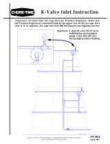
Key Description
1 Auger Direction
2 Intake Cup
3 Cage Floor Support
4 Motor Support Stand
5 Locate the Power Unit in the
center of the cage row.
6 Clean-Out (typical location)
Figure 1. Power Unit Location Diagram for Single Power Unit Systems (top view)
MC656-9 10/97
1
2
3
4
5
Key Description
1 Locate the Power Unit in the
center of the cage row.
2 Intake Cup
3 Cage Floor Support or Motor
Support
4 Auger Direction
5 Clean-Out (typical location)
Figure 2. Power Unit Location Diagram for two Power Unit Systems (top view)

ULTRAFLO
®
Cage Feeding Systems for Brood Grow & Layer Installations Installation for Brood-Grow Cage Systems Only
9
MC656P
Three Power Unit System
Four Power Unit Assembly
If cages are to be removed to allow space for Power Units, cut the Grill, Cage Front,
and Feed Trough Shield from the front of the cage next to a Cage Floor Support
where the Power Unit is to be located. Remove the Top Fronts from this cage also
(See Figure 5.).
5
2
1
5
3
4
4
3
3
6
7
MC656-22 10\97
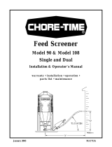
Key Description
1 Locate the Power Unit in the center of
the cage row.
2 Intake Cup
3 Motor Support Stand
4 Cage Floor Support
5 64’ (19.5 m)
6 Auger Direction
7 Clean-Out (typical location)
Figure 3. Power Unit Location Diagram for three Power Unit Systems (top view)
Key Description
1 Intake Cup
2 Cage Floor Stand or Motor Support
3 Systems up to:
500’ (152 m): 80’ (24 m)
500’- 600' (152-183 m): 120’ (37 m)
over 600’ (183 m): 152’ (46 m)
4 Auger Direction
5Clean-Out (typical location)
Figure 4. Power Unit Location Diagram for Four Power Unit Systems (top view)
Key Description
1 Partition
2 Remove the Rings along
the top and bottom
3 Cut wires along the Partition
Figure 5. Modify cage for Power Unit

Installation for Brood-Grow Cage Systems Only ULTRAFLO
®
Cage Feeding Systems for Brood Grow & Layer Installations
10
MC656P
Trough Installation
Trough Support
Note: Refer to the appropriate section for your
cage style.
All Brood-Grow Cage Styles when Step Rail
Brackets are used: Install a Trough Support on each
Cage Floor Support--on the bottom tier (only). (See
Figure 6.)
D.B.S. & Curtain-Backed Brood-Grow Systems ONLY (w/o Step Rail Brackets): Install a
Trough Support on each Cage Floor Support --on all tiers (See Figure 7.).
Do not install Trough Supports on Intermediate Legs.
2 + 2 Brood-Grow Systems ONLY (w/o Step Rail Brackets): Install a Trough Support on each
Cage Floor Support--on tiers #2 and #4 only (See Figure 7.).
Do not install Trough Supports on Intermediate Legs.
Stacked Brood-Grow Systems ONLY (w/o Step Rail Brackets): Install a Trough Support
bottom on tier only (See Figure 7.).
MC656-15 8/95
1
2
Figure 6.
Key Description
1 Trough Support
2 Floor Support
Key Description
1 Trough Support
2 Floor Support
1
2
MC656-46 8/95
Figure 7.

ULTRAFLO
®
Cage Feeding Systems for Brood Grow & Layer Installations Installation for Brood-Grow Cage Systems Only
11
MC656P
Trough
Note: It is very important that the Trough installation be started correctly. When properly
installed, the trough joint will be approximately 8" (20 cm) to the right of the Floor Support.
Refer to Figure 8. when determining trough starting locations, Power Unit-to-Trough
connections, etc.
• Always work from left to right when installing trough.
Trough Sections are shipped in ten foot (3 m) lengths. Four special 11' (3.35 m) Starter Trough
Sections are shipped with each line to be used where needed for proper trough alignment. See
Figures 8 through 13 for Trough Installation.
Various Hangers are used to hold the Trough in place. Refer to Figure 9, 10, or 11 (depending on
your cage style) for identification and correct installation of Hangers.
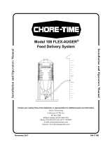
Key Description
1 Standard Trough
2 Standard Trough: Cut off expanded end as required.
3 10' Cage Sections: Use 11' Starter Trough.
8' Cage Sections: Use 9' Starter Trough.
4 Start here.
5Cage Row End
6Cage Row
7 Auger Direction
8 Motor Support Stand
9Clean Out
10 4" (100 mm)
11 Elbow
12 Tube Clamp
13 End Cap
14 Hangers may be installed here on 16" cages.
15 Power Unit Base Connector
16 Mainframe
5
6
2
13
12
11
10
3
16
14
14
2
10
8
4
5
6
6
6
6
5
3
2
3
8
9
2
2
1
2
3
7
1
3
2
3
7
15
1
MC656-81 11/97
Figure 8. Power Unit and Elbow Installation Diagram (top view)

Installation for Brood-Grow Cage Systems Only ULTRAFLO
®
Cage Feeding Systems for Brood Grow & Layer Installations
12
MC656P
Bottom Tier of All Brood-Grow Systems (with Step Rail Brackets)
D.B.S. & Curtain-Backed Brood-Grow Systems
(no Step Rail Brackets)
2 + 2 Brood-Grow & Stacked Brood-Grow (no Step Rail Brackets)
Key Description Part No. Location
1 Wireform Hanger 27107 Install at every partition on
tiers with Feed Trough
Supports.
2 Hold Down Hanger 37111 Install at every partition with
Feed Trough Support.
3 Feed Trough Support 15568 See Trough Support
Installation on page 10.
1
2
3
MC656-68 3/00
Figure 9.Hanger Installation Diagram for Brood-Grow with Step Rail Brackets
(side view)
Key Description part No. Location
1 Wireform 27107 Install at every partition.
2 Feed Trough Support 16204 See Trough Support
Installation on page 10.
3 Trough Wire 39486 See Trough Support
Installation on page 10.
1
3
2
Figure 10.Hanger Installation Diagram for D.B.S. & Curtain-Backed Brood-Grow
(side view)
1
2
3
5
4
Key Description Part No. Location
1 Upper Levels
Hanger
14729 Install at every partition on
all tiers without Feed Trough
Supports.
2 Hold Down
Hanger
37111 Install at every other Cage
Partition.
3 Wireform Hanger 27107 Install at every partition on
tiers with Feed Trough
Supports.
4 Feed Trough
Support
16204 See “Trough Installation”
on page 10.
5 Trough Wire 39486 See “Trough Installation”
on page 10..
Figure 11.Hanger Installation Diagram for 2 + 2 Brood-Grow (side view)

ULTRAFLO
®
Cage Feeding Systems for Brood Grow & Layer Installations Installation for Brood-Grow Cage Systems Only
13
MC656P
Trough Installation (continued)
1. Fasten an End Cap to the end of one of the special 11' (3.35 m) Starter Trough Sections with
self-drilling screws. Begin w/self taper at bulb and work upward
(See Figure 12.).
2. Position the End Cap so that it sticks out 4" (100 mm) past the end of the Cage Row.
(See Figure 12.)
3. Secure the Trough Section to the cages with the Hangers. See Figures 9 Through Figure 11
4. Overlap the straight end of the next Trough Section about 1/4 inch (6 mm) over the expanded
end of the installed Trough. Snap it down into the installed Trough and then slide them together
(See Figure 13.). Fasten the Troughs together with self-drilling screws at the first two joints at
each end of the Cage Row.
5. Continue installing Trough Sections until a location for a Power Unit is reached. Then cut off
a ten foot (3 m) Trough Section as shown in Figure 8. For Power unit installation see “Power
Unit Installation” on page 23 of this manual.
6. After installing the Power Unit, continue installing Trough Sections until another Power Unit
location or the end of the Cage Row is reached.
7. At the end of the Cage Row, cut the Trough so that it sticks out past the end of the Cage Row
4" (100 mm).
8. Slide the End Cap over the cut end of the Trough and fasten with self drilling screws
(See Figure 12.).
MC656-19 8/95
1
4
3
5
2
Key Description
1 4" (100 mm)
2Cages
3 Trough
4 End Cap
5 Self-Drilling Screw
Figure 12.End Cap Installation (top view).
1
2
3
4
MC656-20 10/95
Key Description
1 1/4" (6 mm) Gap
2Snap Down
3 Slide straight end of Trough into belled end of
the next Trough.
4 A self-drilling screw should be installed in this
area on the first two trough joints from both ends.
Figure 13.Trough Connection Diagram (side view).

Installation for Layer Cage Systems Only ULTRAFLO
®
Cage Feeding Systems for Brood Grow & Layer Installations
14
MC656P
Power Unit Location
Determine where the Power Units should be located. Refer Figures 14 through 17 to determine Power
Unit placement.
If the Motor Support Stand is not present as shown, it must be installed according to the instructions
shipped. Refer to instruction MD785 for additional information.
One Power Unit Systems: Place the Power Unit in the center of the cage row (See Figure 14.).
Two Power Unit Systems: The Power Units should be placed in the center of the cage row on opposite
sides of the cage row (See Figure 15.).
Three Power Unit Systems: Three Power Unit Systems require two Power Units on one side and one
on the other side of the Cage Row. The two on the same side should be approximately 64' (19.5 m) from
the ends of the Cage Row. The single Power Unit should be spaced in the center of the Cage Row, on
the opposite side (See Figure 16.).
Four Power Unit Systems: Place the Power Units 80' or 120' (24 or 37 m) from each end of the Cage
Row, depending on the length of the Cage Row (See Figure 17.).
For cage rows with 12" cages, space equal to two vertical rows of cages should be left out at each motor
location for motor installation. If cages were installed, it will be necessary to remove two sets of cages
and install a bolt together Motor Stand 24" (61 cm) from the existing mainframe.
For cages with 16" & 24" cages, space equal to one vertical row of cages should be left out at each motor
location for motor installation. If cages were installed, it will be necessary to remove one set of cages
and install a bolt together Motor Stand 16" (41 cm) or 24" (61 cm) from the existing mainframe
Single Power Unit System.
Two Power Unit System
Installation for Layer Cage Systems Only
Key Description
1 Auger Direction
2 Intake Cup
3 Cage Floor Support
4 Motor Support Stand
5 Locate the Power Unit in the center of
the cage row.
6 Clean-Out (typical location)
MC656-8 10/97
1
3
4
5
6
2
Figure 14.Power Unit Location Diagram for Single Power Unit Systems (top view)
MC656-9 10/97
1
2
3
4
5
Key Description
1 Locate the Power Unit in the
center of the cage row.
2 Intake Cup
3 Cage Floor Support or Motor
Support Stand
4 Auger Direction
5 Clean Out (typical location)
Figure 15.Power Unit Location Diagram for two Power Unit Systems (top view)

ULTRAFLO
®
Cage Feeding Systems for Brood Grow & Layer Installations Installation for Layer Cage Systems Only
15
MC656P
Three Power Unit System
Four Power Unit System
If cages are to be removed to allow space for Power Units, cut the cage front wires shown in Figure
18. to allow room for the Power Unit to be installed.
5
2
1
5
3
4
4
3
3
6
7
MC656-22 10\97
Key Description
1 Locate the Power Unit in the
center of the cage row.
2 Intake Cup
3 Motor Support Stand
4 Cage Floor Support
5 64' (19.5 m)
6 Auger Direction
7 Clean Out (typical location)
Figure 16.Power Unit Location Diagram for Three Power Unit Systems (top view)
Key Description
1 Intake Cup
2 Cage Floor Stand or Motor Support Stand
3 Systems up to 500' (152 m): 80' (24 m)
Systems over 500' (152 m): 120' (37 m)
Systems over 600' (198 m): 152' (46 m)
4 Auger Direction
5 Clean-Out (typical location)
Figure 17.Power Unit Location Diagram for Four Power Unit Systems (top view)
MC656-14 8/95
1
2
2
Key Description
1 Cut out these cage front wires to
allow for motor installation.
2 Cut here.
Figure 18.Modify cage for Power Unit Installation (front view).

Installation for Layer Cage Systems Only ULTRAFLO
®
Cage Feeding Systems for Brood Grow & Layer Installations
16
MC656P
Trough Installation
Trough Hangers
SSS & ST-2 Cage Systems ONLY: Trough Hangers should be hooked on the cages every 4' (1.2
m), beginning at the first “A” frame (See Figure 19.). The last Trough Hanger should be placed
at the end of the cage row, even if the distance from the previous hanger is not 4' (1.2 m).
DURA-CAGE
TM
, DURA-TRIM
TM
, DURA
TM
-STEP, DURA
TM
II, & DURAMID
TM
Cage
Systems ONLY: Install the appropriate style of Hanger in the Cage Floor Supports as shown in
(See Figure 20.) A Trough Hanger should be installed on each side of the Power Units.
Note: At the Power Unit locations, the Hangers for the 15" & 16" cages support the Trough at the
End Cap. The Hangers (with extruded lip) support the Trough several inches from the End Cap.
MC656-41 8/95
1
2
3
4
5
6
Key Description
1 Partition Wire
2 Upper Line Wire
3 Middle Line Wire
4 Litter Shield
5Lower Line Wire
6 Trough Hanger
Figure 19.Trough Hanger Installation for SSE & ST-2 Cage Systems only
MC656-24 10/95
1
23
1
Key Description
1Leg
2 Hanger @ Motor Stand
3 Hanger — for all Cages
Figure 20.Trough Hanger Installation for DURA
TM
Series Cage Systems only (side view).

ULTRAFLO
®
Cage Feeding Systems for Brood Grow & Layer Installations Installation for Layer Cage Systems Only
17
MC656P
Trough
Note: It is very important that the Trough installation be started correctly.
When properly installed, the trough joint will be approximately 8" (20 cm) to the right of
the Cage Support—This dimension should not exceed 12" on Trough Systems. Refer to
Figure 8 when determining trough starting locations, Power Unit-to-Trough connections,
etc.
• Always work from left to right when installing trough.
• On All cage systems with swing down doors, install the cage doors prior to installing the trough.
• The ULTRAFLO
®
Trough is available in 8' (2.4 m) or 10' (3 m) sections (depending on your
cage system). Longer pieces of trough, referred to as Starter Trough (9' or 11'), are sent with
each feeder line (See Figure 21.)
1.Begin at left end of the Cage Row. Install a starter trough to extend 4" (100 mm) past the end
of the cage row and 8" (20 cm) past the Cage Stand (See Figure 22.)
.
2.Attach an End Cap to the Starter Trough Section with self-drilling screws. Begin
w/self tapper at trough bulb and work upward. NOTE: Never lay trough in egg tray. (See
Figure 22.)
3.Position the End Cap so that it sticks out past the end of the Cage Row 4" (100 mm). See
Figure 21 and Figure 22.
Key Description
1 8" (20 cm)
2 Starter Trough
3 4" (100 mm)
4Start Here
5Cage Row End
6 Cage Floor Stand
Figure 21.Starter Trough Location Diagram (top view).
MC656-19 8/95
1
4
3
5
2
Key Description
1 4" (100 mm)
2 Cages
3 Trough
4End Cap
5 Self-Drilling Screw
Figure 22.End Cap Installation (top view).

Installation for Layer Cage Systems Only ULTRAFLO
®
Cage Feeding Systems for Brood Grow & Layer Installations
18
MC656P
4.Overlap the straight end of the next Trough Section over the expanded end of the installed
trough approximately 1/4" (6 mm). Snap it down on the installed trough and slide the
Trough Sections together (See Figure 23.).
5.At the first two joints from each end of the Cage Row, fasten the trough joints together with
self-drilling screws (See Figure 24.).
6.Continue installing Trough Sections until a Power Unit location is reached.
7.See “Power Unit Installation” on page 23, of this manual, for power unit installation
instructions. Then, continue installing Trough Sections until another Power Unit location or
the end of the Cage Row is reached.
8.At the end of the Cage Row, cut the trough so that it extends past the end of the cage row 4"
(100 mm).
9.Slide an End Cap onto the Trough and fasten with self-drilling screws.
1
2
3
MC656-69 10/95
Key Description
1 1/4" (6 mm) Gap
2 Snap Down
3 Slide straight end of Trough into
belled end of the next Trough.
Figure 23.Trough Connection Diagram (side view).
MC656-32 9/9
0
1
Key Description
1 A self-drilling screw should
be installed in this area on the
first two trough joints from
both ends.
Figure 24.Trough Fastening Diagram (side view).

ULTRAFLO
®
Cage Feeding Systems for Brood Grow & Layer Installations Installation for Layer Cage Systems Only
19
MC656P
Retainer Wire Installation (for SSS & ST-2 Only)
Install the Retainer Wire every 4' (1.2 m), beginning one partition beyond the first Floor Support,
as shown in Figure 25.
Trough Clip and Wire Installation (for DURA
TM
Systems Only)
After the Trough has been installed and correctly positioned on the Trough Hanger, install the
Trough Clips as shown in Figure 26. Trough Clips should be located at every other partition,
beginning one partition from the Cage Floor Support and 2" from partition. Crimp the Trough Clips
securely.
Note: Trough Clips are not required on 24" (610 mm) cages and DURA-TRIM
TM
DBS
cages, MANURE BELT cages and VERTICAL DROPPING BOARD SCRAPER CAGES.
MC656-57 8/95
1
3
2
ire
Key Description
1 Litter Shield
2 Layer Trough
3 Retainer Wire
Figure 25.Retainer Wire Installation (side view).
1
2
MC656-38 8/95
Key Description
1 Trough
2 Trough Clip
Figure 26.Trough Clip Installation.

Installation for Layer Cage Systems Only ULTRAFLO
®
Cage Feeding Systems for Brood Grow & Layer Installations
20
MC656P
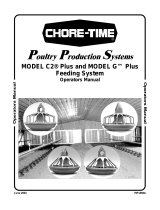
10.Install Trough Wires at every other partition, as shown in Figure 27.
Note: On 24" (610 mm) and 16" (406 mm) DURA-TRIM
TM
DBS & Manure Belt Cages,
install the Trough Wires at every partition.
11.Install the Cage Support Rod, as shown in Figure 27, at each Trough Wire, except at Cage
Floor Supports.
MMB
®
Trough Hanger and Trough Installation
5
4
3
1
2
7
6
MC656-76 8/00
Hook on left side
of partition
Key Description
1 Cage Support Rod
2 This end of Cage Support Rod should hook on
Left side of partition, top, and back wires.
3 This end of Cage Support Rod should hook
over trough and be located between partition
wire and Trough Wire.
4 Hook top of Trough Wire to partition under
line wire.
5Line wire
6 Trough Wire
7 Partition
Figure 27.Trough Wire Installation
Item Description Part No.
1 10-16 x .5 Screw 3037
2 Trough Support 50456
3 Trough Hanger 47654
4 Trough 25399-X
1
2
3
Figure 28.Trough Hanger and Trough (MMB
®
Systems)
4
/