12400 Earl Jones Way, Louisville, KY 40299
(800) 626-1126 | www.rev-a-shelf.com
INSTRUCCIONES
DE INSTALACIÓN
TOOLS REQUIRED:
ESTIMATED ASSEMBLY
TIME:
30 MIN
CARE AND
MAINTENANCE:
Clean with a damp cloth
and wipe parts dry.
30
HERRAMIENTAS
REQUERIDAS:
TIEMPO ESTIMADO CUIDADO Y
MANTENIMIENTO:
LIMPIE CON UN PAÑO HÚMEDO Y
SEQUE BIEN LAS PARTES.
Nota: Antes de iniciar, supervise y asegúrese de que usted tenga todas las partes que aquí se incluyen y la herramienta necesaria para la
instalación. Dependiendo de la construcción de su gabinete, estas instrucciones serán altamente exitosas si usted las sigue paso a paso.
2) Quite el panel (paneles) frontal del fregadero.
1) Usando un lápiz, desde la parte interior del gabinete, trace alrededor del perímetro del marco
de la parte frontal del panel del fregadero. Marque una “T” pequeña en el centro para indicar la
parte superior del fregadero del panel frontal.
Nota: Si va a instalar esto en un lugar donde ya existe un fregadero de cocina, utilice un lápiz pequeño o una puntilla ya que esto le
ayudará a trazar alrededor en espacios ajustados.
Nota: La construcción del gabinete puede variar en diferentes formas, encuentre la mejor manera para quitar el panel frontal del
fregadero a n de no lastimarlo.
Vista interior del gabinete
T
4) Utilizando la plantilla de la extensión que aquí se incluye, cuidadosamente quítela de la
plantilla de la bisagra. Alinee la esquina de la extensión de la plantilla hacia la esquina derecha
del panel frontal del fregadero. Utilizado un lápiz, marque los oricios de ubicación y repita para
el lado izquierdo del panel frontal del fregadero. Si usted tiene otro panel frontal del fregadero,
repita nuevamente el paso número 4.
Panel frontal inferior derecho e izquierdo del fregadero
3) Utilizando la plantilla de la bisagra que aquí se incluye, colóquela en el marco del gabinete
como se muestra y marque dos oricios parapre-taladrar. Repita para el otro lado (pre taladre
utilizado una cabeza de taladro de 3/32”). Esto es altamente recomendado para después
poder tener una instalación sencilla.
5) Ahora tome la plantilla de la bisagra y voltéela en su lado. Utilizando un lápiz, marque el lado
superior derecho e izquierdo de los márgenes. Esto ubicará el lugar en donde las bandejas deben
ser montadas.
Parte superior del panel
6) Deje una de las bandejas en el panel del fregadero asegurándose de que la parte superior de
la bandeja se alinea con las dos marcas que usted hizo en el paso número 5. Una vez alineado,
utilizando un lápiz, marque el centro del oricio como se muestra.
Parte superior del panel
7) Ahora que todos los oricios están marcados, utilizando una cabeza de tornillo de 3/32”,
cuidadosamente taladre todas las marcas de las ubicaciones. Sea muy cuidadoso de NO taladrar a
través del panel.
Dessus du Panneau
8) Utilizando los cuatro tornillos de cabeza de cruz, sujete la bisagra al panel frontal de la tarjeta,
poniendo atención de que hay una bisagra derecha e izquierda. Repita si usted tiene otro panel
frontal del fregadero.
NOTE: las bisagras tienen oricios con ranuras en caso de que usted necesite hacer un ajuste pequeño del panel izquierdo o
derecho del fregadero.
11) Repita para el otro lado de la parte frontal del fregadero y nalmente sujete las bandejas y
apriételas.
9) Utilizando los dos tornillos de cabeza de cruz, sujete como se muestra pero no apriete
totalmente, ya que usted necesitará sujetar la bandeja o bandejas del fregadero a estas tuercas.
10) Tome toda la parte frontal del fregadero y alinéela con la apertura del gabinete mientras se
extiende la bisagra. Sujete la bisagra al marco utilizando los tornillos de cabeza plana que aquí se
incluyen.
Nota: Se recomienda utilizar un desarmador pero utilizar un taladro es mejor si los oricios han sido propiamente pre taladrados.
3/32''
DE LAS BISAGRAS SELFHOLDIN’
ET 45 SOFTCLOSE
DE LAS BISAGRAS EURO:
I-TIPOUT-0415I-TIPOUT-0415I-TIPOUT-0415
equired:
Screw Driver
rill and 3/32" Drill Bit
Saw
ood
nstallation see Steps 1 thru 4 for
’ or Euro hinges and Figures A & B.
CUSTOM POLYMER TRAY INSTALLATION
For Hinge installation see Step 1 thru 4 for Self Holdin; or
Euro hinges and Figure A & B.
Tray Assembly and Installation:
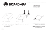
Step 7: The 36” tray in most applications will have to be cut to the
proper length. To obtain proper length, measure the opening
width, then subtract 1-1/2” from the opening width and cut
tray accordingly.
A ne tooth saw is recommended for best results, along with a block of wood
immediately adjacent to cut o point for support as shown in Figure C. Remove any burr
from tray ends.
Step 8: With adhesive provided (please read warnings and directions on adhesive tube), apply
all the way around the inside of the end cap channels, which should suciently hold the
end caps in place.
Step 9: After adhesive has set, locate on end
caps as shown in Figure D mark panel,
drill and mount screws to sucient
depth to allow removal of the tray for
future cleaning.
WARNING: If tray is to be shipped
installed in cabinet “tape
securely to panel.”
Refer to preceding note and helpful hints
for easier installation.
Figure B
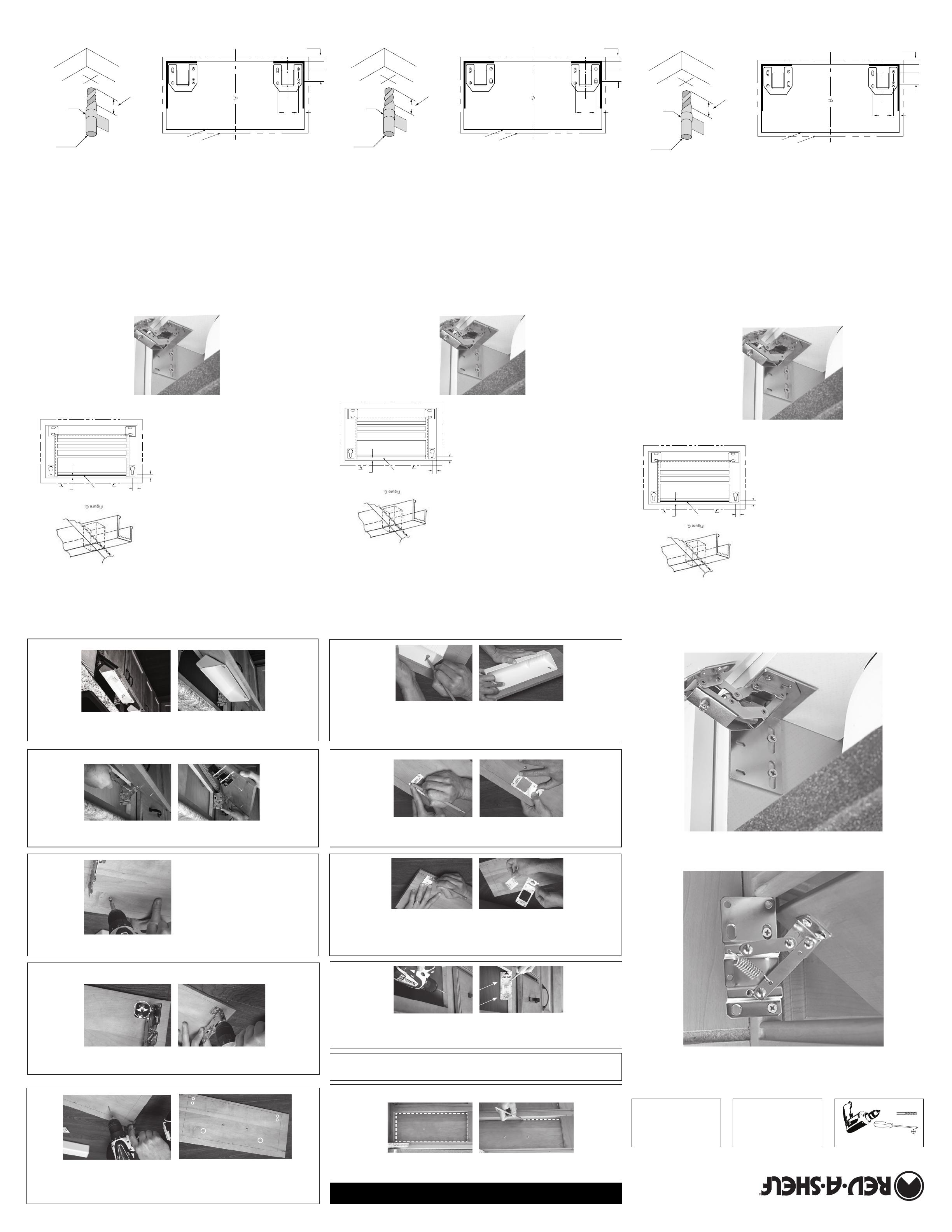
Self-Holdin’ Hinge Installation:
Step 1: Remove front panel or panels from sink cabinet.
Step 2: Install the hinges to both sides of the cabinet as shown in
Figure A. Locate the front edge of the hinges ush with the
outside of the cabinet and install the at head screws
provided in the approximate middle of the elongated holes.
this will allow for a future “up and down” adjustment of ⁄”.
Step 3: Mark the back of the panel with the cabinet opening less
the ⁄”, distances shown in Figure B. Both marks should be
equal from the sides.
Step 4: Measure the height of he elongated slots using the original
panel position as your reference point mark the panel. Install
the panel to the hinges using the Truss Head Screws provided.
Euro Hinge Installation:
Step 1: Remove front panel or panels from sink cabinet.
Step 2: Install the hinges to both sides of the Cabinet as shown
in Figure A. -Locate the front edge of the out side of the
cabinet and install the at head screws provided in the
approximate middle of the elongated holes. this will allow
for a future “up & down” adjustment of ⁄”.
St
ep 3: Mark the back of the panel with the cabinet opening less
⁄”, distances shown in Figure B. Both marks should be
equal from the sides.
Step 4: Measure the height of the elongated slots using the
original panel position as your reference point Mark the
panel. Install the panel to the hinges using the
Truss Head Screws provided.
CHOOSE YOUR HINGE TYPE:
Figure A
The adjustment
screw sets the
desired opening
angle between
45 and 90.
Tools required:
#2 Phillips Screw Driver
Optional Drill and ⁄” drill bit
Fine Tooth Saw (For Custom Trays)
Block of Wood (For Custom Trays)
Helpful Hints
A. A small amount of bar soap on the screw threads will reduce the
initial installation eort.
B. Pre-installation of the screws or pre threading into holes will also
ease nal installation.
C. Your new trays are made from a Hi-Impact Polymer and may be
cleaned using mild soap and water. Avoid scalding water, harsh
abrasives and dishwashers.
POLYMER TRAY (STANDARD & ACCESSORY), STAINLESS, AND SLIM
SERIES TRAY INSTALLATION:
Step 5: Close the panel, reach inside the cabinet and draw a line across the top of the frame
opening on the back of the panel. Open the hinged panel and draw another line
⁄ inch below the top of the Tip-Out Tray.
Step 6: Place the top of the tray against your gaging line, centered between the hinges, and
mark the center of the top portion of the mounting holes. Apply the screws of
sucient depth to allow removal of tray for future cleaning.
Note: In most cases it is easier to remove the panel from the hinges for tray installation,
reinstall and adjust the panel and then slip the tray on the screws.
TIP-OUT TRAY SYSTEM
INSTALLATION INSTRUCTIONS
If you have any questions
please contact a customer
service representative at
1-800-762-9030.
Tools Required:
#2 Phillips Screw Driver
Optional Drill and 3/32" Drill Bit
Fine Tooth Saw
Block of Wood
For Hinge installation see Steps 1 thru 4 for Self
Holdin’ or Euro hinges and Figures A & B.
CUS O S S S
INSTALLATION:
CUSTOM SLIM SERIES TRAY INSTALLATION:
For Hinge installation see Step 1
thru 4 for Self Holdin’ or
Euro hinges and Figure A & B.
Tray Assembly and Installation:
Step 7: The 36” tray in most applications will have to be cut to the
proper length. To obtain proper length, measure the
opening width, then subtract1-1/2” from the opening width
and cut tray accordingly.
Step 8: With adhesive provided (please read warnings and directions on
adhesive tube), apply all the way around the inside of the end cap channels,
which should suciently hold the end caps in place.
Step 9: After adhesive has set, locate tabs on end caps as shown in gure D, mark panel, drill and
mount screws to sucient depth to allow removal of tray for future cleaning.
WARNING: If tray is to be shipped installed in cabinet “Tape securely to panel.”
Refer to preceding note and helpful hints for easier installation.
Rev-A-Shelf, L.L.C.
12400 Earl Jones Way Louisville, KY 40299 • (800) 626-1126 • www.rev-a-shelf.com
3/8"
equired:
Screw Driver
rill and 3/32" Drill Bit
Saw
ood
nstallation see Steps 1 thru 4 for
’ or Euro hinges and Figures A & B.
CUSTOM POLYMER TRAY INSTALLATION
For Hinge installation see Step 1 thru 4 for Self Holdin; or
Euro hinges and Figure A & B.
Tray Assembly and Installation:
Step 7: The 36” tray in most applications will have to be cut to the
proper length. To obtain proper length, measure the opening
width, then subtract 1-1/2” from the opening width and cut
tray accordingly.
A ne tooth saw is recommended for best results, along with a block of wood
immediately adjacent to cut o point for support as shown in Figure C. Remove any burr
from tray ends.
Step 8: With adhesive provided (please read warnings and directions on adhesive tube), apply
all the way around the inside of the end cap channels, which should suciently hold the
end caps in place.
Step 9: After adhesive has set, locate on end
caps as shown in Figure D mark panel,
drill and mount screws to sucient
depth to allow removal of the tray for
future cleaning.
WARNING: If tray is to be shipped
installed in cabinet “tape
securely to panel.”
Refer to preceding note and helpful hints
for easier installation.
Figure B
Self-Holdin’ Hinge Installation:
Step 1: Remove front panel or panels from sink cabinet.
Step 2: Install the hinges to both sides of the cabinet as shown in
Figure A. Locate the front edge of the hinges ush with the
outside of the cabinet and install the at head screws
provided in the approximate middle of the elongated holes.
this will allow for a future “up and down” adjustment of ⁄”.
Step 3: Mark the back of the panel with the cabinet opening less
the ⁄”, distances shown in Figure B. Both marks should be
equal from the sides.
Step 4: Measure the height of he elongated slots using the original
panel position as your reference point mark the panel. Install
the panel to the hinges using the Truss Head Screws provided.
Euro Hinge Installation:
Step 1: Remove front panel or panels from sink cabinet.
Step 2: Install the hinges to both sides of the Cabinet as shown
in Figure A. -Locate the front edge of the out side of the
cabinet and install the at head screws provided in the
approximate middle of the elongated holes. this will allow
for a future “up & down” adjustment of ⁄”.
St
ep 3: Mark the back of the panel with the cabinet opening less
⁄”, distances shown in Figure B. Both marks should be
equal from the sides.
Step 4: Measure the height of the elongated slots using the
original panel position as your reference point Mark the
panel. Install the panel to the hinges using the
Truss Head Screws provided.
CHOOSE YOUR HINGE TYPE:
Figure A
The adjustment
screw sets the
desired opening
angle between
45 and 90.
Tools required:
#2 Phillips Screw Driver
Optional Drill and ⁄” drill bit
Fine Tooth Saw (For Custom Trays)
Block of Wood (For Custom Trays)
Helpful Hints
A. A small amount of bar soap on the screw threads will reduce the
initial installation eort.
B. Pre-installation of the screws or pre threading into holes will also
ease nal installation.
C. Your new trays are made from a Hi-Impact Polymer and may be
cleaned using mild soap and water. Avoid scalding water, harsh
abrasives and dishwashers.
POLYMER TRAY (STANDARD & ACCESSORY), STAINLESS, AND SLIM
SERIES TRAY INSTALLATION:
Step 5: Close the panel, reach inside the cabinet and draw a line across the top of the frame
opening on the back of the panel. Open the hinged panel and draw another line
⁄ inch below the top of the Tip-Out Tray.
Step 6: Place the top of the tray against your gaging line, centered between the hinges, and
mark the center of the top portion of the mounting holes. Apply the screws of
sucient depth to allow removal of tray for future cleaning.
Note: In most cases it is easier to remove the panel from the hinges for tray installation,
reinstall and adjust the panel and then slip the tray on the screws.
TIP-OUT TRAY SYSTEM
INSTALLATION INSTRUCTIONS
If you have any questions
please contact a customer
service representative at
1-800-762-9030.
Tools Required:
#2 Phillips Screw Driver
Optional Drill and 3/32" Drill Bit
Fine Tooth Saw
Block of Wood
For Hinge installation see Steps 1 thru 4 for Self
Holdin’ or Euro hinges and Figures A & B.
CUS O S S S
INSTALLATION:
CUSTOM SLIM SERIES TRAY INSTALLATION:
For Hinge installation see Step 1
thru 4 for Self Holdin’ or
Euro hinges and Figure A & B.
Tray Assembly and Installation:
Step 7: The 36” tray in most applications will have to be cut to the
proper length. To obtain proper length, measure the
opening width, then subtract1-1/2” from the opening width
and cut tray accordingly.
Step 8: With adhesive provided (please read warnings and directions on
adhesive tube), apply all the way around the inside of the end cap channels,
which should suciently hold the end caps in place.
Step 9: After adhesive has set, locate tabs on end caps as shown in gure D, mark panel, drill and
mount screws to sucient depth to allow removal of tray for future cleaning.
WARNING: If tray is to be shipped installed in cabinet “Tape securely to panel.”
Refer to preceding note and helpful hints for easier installation.
Rev-A-Shelf, L.L.C.
12400 Earl Jones Way Louisville, KY 40299 • (800) 626-1126 • www.rev-a-shelf.com
3/8"
CUSTOM POLYMER TRAY INSTALLATION
6551,6552,6571,6541, 6542
Step 1: The 36'' tray in most applications will have to be cut
to the proper length. To obtain proper length, measure the
opening width, then subtract 1-1/2'' from the opening width
ans cut tray accordingly.
A ne tooth saw is recommended for best results, along with
a block of wood immediately adjacent to cut o point for
support as shown in Figure C. Remove any burr from tray
ends.
Step 2: With adhesive provided (please read warnings and
directions on adhesive tube), apply all the way around the
inside of the end cap channels, which should suciently hold
the end caps in place.
Step 3: After adhesive has set, locate on end caps as shown
in Figure D mark panel, drill and mount screws to sucient
depth to allow removal of the tray for future cleaning.
I-TIPOUT-0415 I-TIPOUT-0415 I-TIPOUT-0415
A
Figure D
OPENING
A = DESIRED OVERLAY
PANEL
3/8''
7/16''
3/4''
1 1/4''
A
Figure D
OPENING
A = DESIRED OVERLAY
PANEL
3/8''
7/16''
3/4''
1 1/4''
A
Figure D
OPENING
A = DESIRED OVERLAY
PANEL
3/8''
7/16''
3/4''
1 1/4''
NOT THRU
PANEL
TYPICAL
(OPTIONAL)
TAPE
DIA.
DRILL BIT
3/32”
7/16”
NOT THRU
PANEL
TYPICAL
(OPTIONAL)
TAPE
DIA.
DRILL BIT
3/32”
7/16”
NOT THRU
PANEL
TYPICAL
(OPTIONAL)
TAPE
DIA.
DRILL BIT
3/32”
7/16”
5/16''
T YP.
15/32''
T YP.
PANEL
TOP OF TRAY
7/32'' REF.
PANEL OPENING
Figure B
Figure A
The adjustment
screw sets the
desired opening
angle between
45 and 90.
Tools Required:
#2 Phillips Screw Driver
Optional Drill and 3/32" Drill Bit
Fine Tooth Saw
Block of Wood
For Hinge installation see Steps 1 thru 4 for Self
Holdin’ or Euro hinges and Figures A & B.
INSTALLATION:
Required:
s Screw Driver
Drill and 3/32" Drill Bit
h Saw
Wood
e installation see Steps 1 thru 4 for
Figure B
INSTALACIÓN DE LAS BANDEJAS DE LA SERIE
SLIM A LA MEDIDA:
Para la instalación de las bisagras,
consulte los Pasos 1 a 4 para
las bisagras Self Holdin’ o Euro
y las Figuras A y B.
Armado e instalación de las bandejas:
Paso 7: En la mayoría de las aplicaciones, la bandeja de 914 mm
(36 pulgadas) tendrá que cortarse al largo apropiado. Para obtener
el largo apropiado, mida el ancho de la abertura,
réstele 38 mm (1½ pulgadas) y corte la bandeja de acuerdo con ello.
Se recomienda una sierra de dientes nos para obtener mejores resultados, junto con
un bloque de madera inmediatamente adyacente al punto de corte como apoyo, tal
como se muestra en la Figura C. Quite todas las rebabas de los extremos de la bandeja.
Paso 8: Aplique una cantidad suciente del adhesivo suministrado (sírvase leer las advertencias
e instrucciones en el tubo de adhesivo), a todo alrededor del interior de los canales de
las tapas de los extremos para retenerlas en posición.
Paso 9: Una vez fraguado el adhesivo, identique las lengüetas en las tapas de los extremos,
tal como se muestra en la gura D, marque el panel, taladre e instale los tornillos a una
profundidad suciente para permitir retirar la bandeja para su limpieza futura.
ADVERTENCIA: Si la bandeja se enviará instalada
en el armario, “encíntela rmemente al panel”.
Consulte la nota previa y las recomendaciones
útiles para facilitar la instalación.
Instalación de las bisagras Self-Holdin’:
Paso 1: Retire el panel o paneles delanteros del armario para lavamanos.
Paso 2: Instale las bisagras en ambos lados del armario como en la parte
de afuera del mismo y coloque los tornillos de cabeza plana
suministrados, aproximadamente en el medio de los agujeros
alargados. Esto permitirá realizar un ajuste “hacia arriba y abajo”
de ⁄ pulgada en el futuro.
Paso 3: Marque la parte de atrás del panel con la abertura del armario
menos ⁄ pulgada, distancias mostradas en la Figura B.
Ambas marcas deben ser iguales desde los costados.
Paso 4: Mida la altura de las ranuras alargadas usando la posición
original del panel como punto de referencia. Marque el panel.
Instale el panel en las bisagras con los tornillos de cabeza
segmentada suministrados.
Instalación de las bisagras Euro:
Paso 1: Retire el panel o paneles delanteros del armario para lavamanos.
Paso 2: Instale las bisagras en ambos lados del armario, tal como se
muestra en la Figura A. Sitúe el borde delantero de las bisagras
a ras con la par
te de afuera del armario e instale los tornillos
de cabeza plana suministrados aproximadamente en el medio
de los agujeros alargados. Esto permitirá realizar un ajuste
“hacia arriba y abajo” de 5 mm (⁄ pulgada) en el futuro.
Paso 3: Marque la parte de atrás del panel con la abertura del armario
menos 10 mm (⁄ pulgada), distancias mostradas en la Figura B.
Ambas marcas deben ser iguales desde los costados.
Paso 4: Mida la altura de las ranuras alargadas usando la posición original del panel como punto de
referencia. Marque el panel. Instale el panel en las bisagras con los tornillos de cabeza segmentada suministrados.
CHOOSE YOUR HINGE TYPE:
Herramientas requeridas:
Destornillador Phillips Nº 2
Taladro y broca de 3/32 pulg. opcionales
Sierra de dientes nos (Para las costumbre banduja)
Bloque de madera (Para las costumbre banduja)
Recomendaciones útiles
A. Una pequeña cantidad de jabón de barra sobre las roscas del tornillo
reducirán el esfuerzo de instalación inicial.
B. La preinstalación de los tornillos o el roscado preliminar en los
agujeros también facilitará la instalación nal.
C. Las bandejas nuevas son de polímero resistente a los impactos
y pueden limpiarse con agua y jabón suave. Evite el agua hirviendo,
los abrasivos fuertes y las lavadoras de platos.
INSTALACIÓN DE BANDEJAS DE POLÍMERO (ESTÁNDAR Y AUXILIAR),
DE ACERO INOXIDABLE Y DE LA SERIE SLIM:
Paso 5: Cierre el panel, alcance dentro del armario y trace una línea de un lado a otro en el extremo
superior de la abertura del marco en la parte trasera del panel. Abra el panel abisagrado y trace
otra línea 3 mm (1/8 pulg.) por debajo del extremo superior de la línea del marco. Esta línea
nueva es la línea indicadora para el extremo superior de la bandeja inclinable.
Paso 6: Sitúe el extremo superior de la bandeja contra la línea indicadora, centrada entre las bisagras
y marque el centro de la sección superior de los agujeros de montaje. Coloque los tornillos a una
profundidad suciente para permitir retirar la bandeja para limpiarla en el futuro. Nota: En la
mayoría de los casos es más fácil quitar el panel de las bisagras para instalar la bandeja,
reinstalar y ajustar el panel y entonces deslizar la bandeja sobre los tornillos.
INSTRUCCIONES DE INSTALACIÓN PARA EL
SISTEMA DE BANDEJAS INCLINABLES
Si tiene preguntas, comuníquese con
los especialistas de servicio al cliente
llamando al 1-800-762-9030.
Rev-A-Shelf, L.L.C.
12400 Earl Jones Way Louisville, KY 40299 • (800) 626-1126 • www.rev-a-shelf.com
INSTALACIÓN DE BANDEJAS DE POLÍMERO
A LA MEDIDA:
Para la instalación de las bisagras, consulte los
Pasos 1 a 4 para las bisagras Self Holdin’ o
Euro y las Figuras A y B.
Armado e instalación de las bandejas:
Paso 7: En la mayoría de las aplicaciones, la bandeja de 914 mm
(36 pulgadas) tendrá que cortarse al largo apropiado. Para obtener el
largo apropiado, mida el ancho de la abertura, réstele 38 mm (1½ pulgadas) y cort
e
la bandeja de acuerdo con ello.
Se recomienda una sierra de dientes nos para obtener mejores resultados, junto con
un bloque de madera inmediatamente adyacente al punto de corte como apoyo, tal
como se muestra en la Figura C. Quite todas las rebabas de los extremos de la bandeja.
Paso 8: Aplique una cantidad suciente
del adhesivo suministrado (sírvase
leer las advertencias e instrucciones
en el tubo de adhesivo), a todo
alrededor del interior de los canales
de las tapas de los extremos para
retenerlas en posición.
Paso 9: Una vez fraguado el adhesivo,
identique las lengüetas en las tapas
de los extremos, tal como se muestra
en la gura D, marque el panel,
taladre e instale los tornillos a una
profundidad suciente para permitir retirar la bandeja para su limpieza futura.
ADVERTENCIA: Si la bandeja se enviará instalada en el armario, “encíntela rmemente al panel”.
Consulte la nota previa y las recomendaciones útiles para facilitar la instalación.
Lado izquierdo,
armario sin
marco mostrado
Lado derecho,
armario enmarcado
mostrado
Figura A
Figura B
Figura A
Figura B
TÍPICO
(OPCIONAL)
11 mm (7/16 Pulg)
NO
ATRAVIESA
EL PANEL
CINTA
BROCA DE 3/32
Pulg DE DIÁM.
ABERTURA
SUPERPOSICIÓN
DESEADA
(VER EL PASO 3)
MARCAR EL PANEL
MARCAR EL
PANEL
21 mm
(5/8 Pulg) TÍP.
BROCA DE 3/32
Pulg DE DIÁM.
CINTA
TÍPICO
(OPCIONAL)
11 mm (7/16 Pulg)
NO
ATRAVIESA
EL PANEL
ABERTURA
SUPERPOSICIÓN
DESEADA
(VER EL PASO 3)
Lado izquierdo,
armario sin
Lado derecho,
armario enmarcado
El tornillo de ajuste ja
el ángulo de abertura
deseado entre
45 y 90 grados.
EXTREMO SUPERIOR DE LA BANDEJA
ABERTURA DEL PANEL
Figura D
Figura C
Figura C
EXTREMO SUPERIOR DE LA BANDEJA
ABERTURA DEL PANEL
Figura D
9.5 mm
Figure A
The adjustment
screw sets the
desired opening
angle between
45 and 90.
Tools Required:
#2 Phillips Screw Driver
Optional Drill and 3/32" Drill Bit
Fine Tooth Saw
Block of Wood
For Hinge installation see Steps 1 thru 4 for Self
Holdin’ or Euro hinges and Figures A & B.
INSTALLATION:
Required:
s Screw Driver
Drill and 3/32" Drill Bit
h Saw
Wood
e installation see Steps 1 thru 4 for
Figure B
INSTALACIÓN DE LAS BANDEJAS DE LA SERIE
SLIM A LA MEDIDA:
Para la instalación de las bisagras,
consulte los Pasos 1 a 4 para
las bisagras Self Holdin’ o Euro
y las Figuras A y B.
Armado e instalación de las bandejas:
Paso 7: En la mayoría de las aplicaciones, la bandeja de 914 mm
(36 pulgadas) tendrá que cortarse al largo apropiado. Para obtener
el largo apropiado, mida el ancho de la abertura,
réstele 38 mm (1½ pulgadas) y corte la bandeja de acuerdo con ello.
Se recomienda una sierra de dientes nos para obtener mejores resultados, junto con
un bloque de madera inmediatamente adyacente al punto de corte como apoyo, tal
como se muestra en la Figura C. Quite todas las rebabas de los extremos de la bandeja.
Paso 8: Aplique una cantidad suciente del adhesivo suministrado (sírvase leer las advertencias
e instrucciones en el tubo de adhesivo), a todo alrededor del interior de los canales de
las tapas de los extremos para retenerlas en posición.
Paso 9: Una vez fraguado el adhesivo, identique las lengüetas en las tapas de los extremos,
tal como se muestra en la gura D, marque el panel, taladre e instale los tornillos a una
profundidad suciente para permitir retirar la bandeja para su limpieza futura.
ADVERTENCIA: Si la bandeja se enviará instalada
en el armario, “encíntela rmemente al panel”.
Consulte la nota previa y las recomendaciones
útiles para facilitar la instalación.
Instalación de las bisagras Self-Holdin’:
Paso 1: Retire el panel o paneles delanteros del armario para lavamanos.
Paso 2: Instale las bisagras en ambos lados del armario como en la parte
de afuera del mismo y coloque los tornillos de cabeza plana
suministrados, aproximadamente en el medio de los agujeros
alargados. Esto permitirá realizar un ajuste “hacia arriba y abajo”
de ⁄ pulgada en el futuro.
Paso 3: Marque la parte de atrás del panel con la abertura del armario
menos ⁄ pulgada, distancias mostradas en la Figura B.
Ambas marcas deben ser iguales desde los costados.
Paso 4: Mida la altura de las ranuras alargadas usando la posición
original del panel como punto de referencia. Marque el panel.
Instale el panel en las bisagras con los tornillos de cabeza
segmentada suministrados.
Instalación de las bisagras Euro:
Paso 1: Retire el panel o paneles delanteros del armario para lavamanos.
Paso 2: Instale las bisagras en ambos lados del armario, tal como se
muestra en la Figura A. Sitúe el borde delantero de las bisagras
a ras con la par
te de afuera del armario e instale los tornillos
de cabeza plana suministrados aproximadamente en el medio
de los agujeros alargados. Esto permitirá realizar un ajuste
“hacia arriba y abajo” de 5 mm (⁄ pulgada) en el futuro.
Paso 3: Marque la parte de atrás del panel con la abertura del armario
menos 10 mm (⁄ pulgada), distancias mostradas en la Figura B.
Ambas marcas deben ser iguales desde los costados.
Paso 4: Mida la altura de las ranuras alargadas usando la posición original del panel como punto de
referencia. Marque el panel. Instale el panel en las bisagras con los tornillos de cabeza segmentada suministrados.
CHOOSE YOUR HINGE TYPE:
Herramientas requeridas:
Destornillador Phillips Nº 2
Taladro y broca de 3/32 pulg. opcionales
Sierra de dientes nos (Para las costumbre banduja)
Bloque de madera (Para las costumbre banduja)
Recomendaciones útiles
A. Una pequeña cantidad de jabón de barra sobre las roscas del tornillo
reducirán el esfuerzo de instalación inicial.
B. La preinstalación de los tornillos o el roscado preliminar en los
agujeros también facilitará la instalación nal.
C. Las bandejas nuevas son de polímero resistente a los impactos
y pueden limpiarse con agua y jabón suave. Evite el agua hirviendo,
los abrasivos fuertes y las lavadoras de platos.
INSTALACIÓN DE BANDEJAS DE POLÍMERO (ESTÁNDAR Y AUXILIAR),
DE ACERO INOXIDABLE Y DE LA SERIE SLIM:
Paso 5: Cierre el panel, alcance dentro del armario y trace una línea de un lado a otro en el extremo
superior de la abertura del marco en la parte trasera del panel. Abra el panel abisagrado y trace
otra línea 3 mm (1/8 pulg.) por debajo del extremo superior de la línea del marco. Esta línea
nueva es la línea indicadora para el extremo superior de la bandeja inclinable.
Paso 6: Sitúe el extremo superior de la bandeja contra la línea indicadora, centrada entre las bisagras
y marque el centro de la sección superior de los agujeros de montaje. Coloque los tornillos a una
profundidad suciente para permitir retirar la bandeja para limpiarla en el futuro. Nota: En la
mayoría de los casos es más fácil quitar el panel de las bisagras para instalar la bandeja,
reinstalar y ajustar el panel y entonces deslizar la bandeja sobre los tornillos.
INSTRUCCIONES DE INSTALACIÓN PARA EL
SISTEMA DE BANDEJAS INCLINABLES
Si tiene preguntas, comuníquese con
los especialistas de servicio al cliente
llamando al 1-800-762-9030.
Rev-A-Shelf, L.L.C.
12400 Earl Jones Way Louisville, KY 40299 • (800) 626-1126 • www.rev-a-shelf.com
INSTALACIÓN DE BANDEJAS DE POLÍMERO
A LA MEDIDA:
Para la instalación de las bisagras, consulte los
Pasos 1 a 4 para las bisagras Self Holdin’ o
Euro y las Figuras A y B.
Armado e instalación de las bandejas:
Paso 7: En la mayoría de las aplicaciones, la bandeja de 914 mm
(36 pulgadas) tendrá que cortarse al largo apropiado. Para obtener el
largo apropiado, mida el ancho de la abertura, réstele 38 mm (1½ pulgadas) y corte
la bandeja de acuerdo con ello.
Se recomienda una sierra de dientes nos para obtener mejores resultados, junto con
un bloque de madera inmediatamente adyacente al punto de corte como apoyo, tal
como se muestra en la Figura C. Quite todas las rebabas de los extremos de la bandeja.
Paso 8: Aplique una cantidad suciente
del adhesivo suministrado (sírvase
leer las advertencias e instrucciones
en el tubo de adhesivo), a todo
alrededor del interior de los canales
de las tapas de los extremos para
retenerlas en posición.
Paso 9: Una vez fraguado el adhesivo,
identique las lengüetas en las tapas
de los extremos, tal como se muestra
en la gura D, marque el panel,
taladre e instale los tornillos a una
profundidad suciente para permitir retirar la bandeja para su limpieza futura.
ADVERTENCIA: Si la bandeja se enviará instalada en el armario, “encíntela rmemente al panel”.
Consulte la nota previa y las recomendaciones útiles para facilitar la instalación.
Lado izquierdo,
armario sin
marco mostrado
Lado derecho,
armario enmarcado
mostrado
Figura A
Figura B
Figura A
Figura B
TÍPICO
(OPCIONAL)
11 mm (7/16 Pulg)
NO
ATRAVIESA
EL PANEL
CINTA
BROCA DE 3/32
Pulg DE DIÁM.
ABERTURA
SUPERPOSICIÓN
DESEADA
(VER EL PASO 3)
MARCAR EL PANEL
MARCAR EL
PANEL
21 mm
(5/8 Pulg) TÍP.
BROCA DE 3/32
Pulg DE DIÁM.
CINTA
TÍPICO
(OPCIONAL)
11 mm (7/16 Pulg)
NO
ATRAVIESA
EL PANEL
ABERTURA
SUPERPOSICIÓN
DESEADA
(VER EL PASO 3)
Lado izquierdo,
armario sin
Lado derecho,
armario enmarcado
El tornillo de ajuste ja
el ángulo de abertura
deseado entre
45 y 90 grados.
EXTREMO SUPERIOR DE LA BANDEJA
ABERTURA DEL PANEL
Figura D
Figura C
Figura C
EXTREMO SUPERIOR DE LA BANDEJA
ABERTURA DEL PANEL
Figura D
9.5 mm
INSTALACIÓN DE BANDEJAS DE POLÍMERO A LA MEDIDA:
6551,6552,6571,6541, 6542
Para la instalación de las bisagras, consulte los Pasos 1 a 4 para las bisagras Self Holdin’ o
Euro y las Figuras A y B.
Armado e instalación de las bandejas:
Paso 1: En la mayoría de las aplicaciones, la bandeja de 914 mm
(36 pulgadas) tendrá que cortarse al largo apropiado. Para
obtener el
largo apropiado, mida el ancho de la abertura, réstele 38 mm (1½
pulgadas) y corte la bandeja de acuerdo con ello. Se recomienda
una sierra de dientes “nos para obtener mejores resultados, junto
con un bloque de madera inmediatamente adyacente al punto de
corte como apoyo, tal como se muestra en la Figura C. Quite todas
las rebabas de los extremos de la bandeja.
Paso 2: Aplique una cantidad su”ciente del adhesivo suministrado
(sírvase leer las advertencias e instrucciones en el tubo de
adhesivo), a todo alrededor del interior de los canales de las tapas
de los extremos para retenerlas en posición.
Paso 3: Una vez fraguado el adhesivo, identi”que las lengüetas
en las tapas de los extremos, tal como se muestra en la “gura D,
marque el panel,
taladre e instale los tornillos a una profundidad su”ciente para
permitir retirar la bandeja para su limpieza futura.
ADVERTENCIA: Si la bandeja se enviará instalada en el armario, “encíntela “rmemente
al panel”. Consulte la nota previa y las recomendaciones útiles para facilitar la
instalación.
5/16''
T YP.
15/32''
T YP.
PANEL
TOP OF TRAY
7/32'' REF.
PANEL OPENING
Figure B
Paso 4:
Mida la altura de las ranuras alargadas usando la posición original del
panel como punto de referencia. Marque el panel. Instale el panel en
las bisagras con los tornillos de cabeza segmentada suministrados.
Figure A
The adjustment
screw sets the
desired opening
angle between
45 and 90.
Tools Required:
#2 Phillips Screw Driver
Optional Drill and 3/32" Drill Bit
Fine Tooth Saw
Block of Wood
For Hinge installation see Steps 1 thru 4 for Self
Holdin’ or Euro hinges and Figures A & B.
INSTALLATION:
Required:
s Screw Driver
Drill and 3/32" Drill Bit
h Saw
Wood
e installation see Steps 1 thru 4 for
Figure B
INSTALLATION DE L’ÉTAGÈRE SUR MESURE
DE LA SÉRIE « SLIM »
Pour l’installation
des charnières,
consulter les étapes 1 à 4
des instructions pour « Self Holdin’ »
ou Charnières européennes, ainsi que les gures A et B.
Assemblage et installation du bac
Étape 7 Dans la majorité des utilisations, il faut couper le bac de
914 mm (36 po) à la longueur appropriée. Pour obtenir la longueur
appropriée, mesurer la largeur de l’ouverture et soustraire
38 mm (1½ po) de la largeur de l’ouverture et couper le bac selon le besoin.
Pour obtenir les meilleurs résultats, il est recommandé d’utiliser une scie à dents nes,
le long d’un bloc de bois immédiatement adjacent au point de support, comme montré
à la gure C. Enlever toutes les bavures des extrémités du bac.
Étape 8 Avec l’adhésif fourni (lire les avertissements et les instructions sur le tube d’adhésif),
appliquer tout autour dans les rainures des embouts, ce qui devrait être susant pour
maintenir les embouts en place.
Étape 9 Après le séchage de l’adhésif, placer les languettes sur les embouts, comme montré à la
gure D, marquer le panneau, percer et visser les vis à une profondeur susante pour
permettre l’enlèvement du bac pour le nettoyer plus tard.
MISE EN GARDE – Si le bac doit être expédié
installé dans le placard, l’attacher fermement
au panneau avec du ruban adhésif.
Consulter la note précédente et les conseils utiles
pour faciliter l’installation.
Installation des charnières « Self-Holdin’ »
Étape 1 Déposer le panneau avant ou les panneaux du placard de l’évier.
Étape 2 Installer les charnières des deux côtés du placard, comme montré à la
gure A. Placer le bord avant des charnières de niveau avec le bord
extérieur du placard et installer les vis à tête plate fournies,
approximativement au milieu des trous allongés. Ceci permet le
réglage ultérieur de 5 mm (⁄ po) vers le haut ou le bas.
Étape 3 Marquer le dos du panneau avec l’ouverture du placard, moins la
distance de 17,5 mm (⁄ po) montrée à la gure B. Les deux marques
doivent être à la même distance des deux côtés.
Étape 4 Mesurer la hauteur des fentes allongées en utilisant la position du
panneau original comme référence. Marquer le panneau. Installer le
panneau sur les charnières en utilisant les vis à tête bombée fournies.
Installation de la charnière européenne
Étape 1 Déposer le panneau avant ou les panneaux du placard de l’évier.
Étape 2 Installer les charnières des deux c
ôtés du placard, comme montré à la gure A.
Placer le bord avant des charnières de niveau avec le bord extérieur du placard
et installer les vis à tête plate fournies, approximativement au
milieu des trous allongés. Ceci permet le réglage ultérieur de
5 mm (⁄ po) vers le haut ou le bas.
Étape 3 Marquer le dos du panneau avec l’ouverture du placard, moins
la distance de 10 mm (⁄ po) montrée à la gure B. Les deux
marques doivent être à la même distance des deux côtés.
Étape 4 Mesurer la hauteur des fentes allongées en utilisant la position du panneau
original comme référence. Marquer le panneau. Installer le panneau sur les charnières
en utilisant les vis à tête bombée fournies.
CHOOSE YOUR HINGE TYPE:
Outils nécessaires
Tournevis cruciforme n° 2
En option, perceuse avec foret de 3/32 po
Scie à dents nes (Pour les tiroirs sur mesure)
Bloc de bois (Pour les tiroirs sur mesure)
Conseils utiles
A. Un peu de savon sur les lets de vis aide à réduire l’eort initial
pour l’installation.
B. Installer les vis ou les visser dans les trous avant l’installation aide
aussi pour l’installation nale.
C. Les bacs neufs sont faits de polymère à grande résistance et il est
possible de les laver avec de l’eau et du savon. Éviter l’eau très chaude,
les produits abrasifs et les lave-vaisselle.
INSTALLATION DU BAC EN POLYMÈRE (STANDARD ET ACCESSOIRE),
EN ACIER INOXYDABLE ET DE LA SÉRIE MINCE
Étape 5 Fermer le panneau, atteindre à l’intérieur du placard et tirer une ligne le long du haut
de l’ouverture du bâti, au dos du panneau. Ouvrir le panneau à charnière et tirer une autre ligne,
3 mm (⁄ po) au dessous du haut de la ligne du bâti. Cette nouvelle ligne est la ligne de référence
pour le haut du bac basculant.
Étape 6 Placer le haut du bac contre la ligne de référence, centrer entre les charnières et marquer le
centre de la portion supérieure des trous de montage. Appliquer les vis à une profondeur
susante pour permettre d’enlever le bac pour le nettoyer plus tard. Nota – Dans la majorité
des cas, il est plus facile d’enlever le panneau des charnières pour installer le bac, de remonter et
de régler le panneau et de glisser ensuite le bac sur les vis.
INSTRUCTIONS D’INSTALLATION DU
SYSTÈME DE BAC BASCULANT
En cas de questions, contacter
nos spécialistes de service
après-vente à 1-800-762-9030.
Rev-A-Shelf, L.L.C.
12400 Earl Jones Way Louisville, KY 40299 • (800) 626-1126 • www.rev-a-shelf.com
INSTALLATION DU BAC EN POLYMÈRE
SUR MESURE
Pour l’installation des charnières, consulter les
étapes 1 à 4 des instructions pour « Self Holdin’ »
ou Charnières européennes, ainsi que les gures A et B.
Assemblage et installation du bac
Étape 7 Dans la majorité des utilisations, il faut couper le bac de
914 mm (36 po) à la longueur appropriée. Pour obtenir la longueur
appropriée, mesurer la largeur de l’ouverture et soustraire 38 mm (1½ po) de la largeur
de l’ouverture et couper le bac selon le besoin.
Pour obtenir les meilleurs résultats, il est recommandé d’utiliser une scie à dents nes,
le long d’un bloc de bois immédiatement adjacent au point de support, comme montré
à la gure C. Enlever toutes les bavures des extrémités du bac.
Étape 8
Avec l’adhésif fourni (lire les
avertissements et les instructions sur le
tube d’adhésif), appliquer tout autour
dans les rainures des embouts, ce qui
devrait être susant pour maintenir les
embouts en place.
Étape 9 Après le séchage de l’adhésif, placer les
languettes sur les embouts, comme montré
à la gure D, marquer le panneau, percer et
visser les vis à une profondeur susante
pour permettre l’enlèvement du bac pour
le nettoyer plus tard.
MISE EN GARDE – Si le bac doit être expédié installé dans le placard, l’attacher fermement au
panneau avec du ruban adhésif. Consulter la note précédente et les conseils utiles pour faciliter
l’installation.
Côté gauche
du placard sans
bâti
Côté droit du placard
avec bâti
TYPIQUE
(OPTIONNEL)
11 mm (7/16 PO.)
PAS À
TRAVERS LE
PANNEAU
RUBAN
FORET DE
3/32 PO
OUVERTURE
RECOUVREMENT
DÉSIRÉ
(VOIR ÉTAPE 3)
MARQUER LE
PANNEAU
MARQUER LE
PANNEAU
21 mm
(5/8 PO.) TÍP.
FORET DE
3/32 PO
RUBAN
TYPIQUE
(OPTIONNEL)
11 mm (7/16 PO.)
PAS À
TRAVERS LE
PANNEAU
OUVERTURE
RECOUVREMENT
DÉSIRÉ
(VOIR ÉTAPE 3)
Côté gauche
du placard sans
bâti montré
Côté droit du placard
avec bâti montré
La vis de réglage
dénit l’angle
d’ouverture entre
45 et 90°
Figure C
Figure C
HAUT DU BAC
OUVERTURE
DU PANNEAU
PANNEAU
PANNEAU
HAUT DU BAC
OUVERTURE
DU PANNEAU
PANNEAU
Figure A
The adjustment
screw sets the
desired opening
angle between
45 and 90.
Tools Required:
#2 Phillips Screw Driver
Optional Drill and 3/32" Drill Bit
Fine Tooth Saw
Block of Wood
For Hinge installation see Steps 1 thru 4 for Self
Holdin’ or Euro hinges and Figures A & B.
INSTALLATION:
Required:
s Screw Driver
Drill and 3/32" Drill Bit
h Saw
Wood
e installation see Steps 1 thru 4 for
Figure B
INSTALLATION DE L’ÉTAGÈRE SUR MESURE
DE LA SÉRIE « SLIM »
Pour l’installation
des charnières,
consulter les étapes 1 à 4
des instructions pour « Self Holdin’ »
ou Charnières européennes, ainsi que les gures A et B.
Assemblage et installation du bac
Étape 7 Dans la majorité des utilisations, il faut couper le bac de
914 mm (36 po) à la longueur appropriée. Pour obtenir la longueur
appropriée, mesurer la largeur de l’ouverture et soustraire
38 mm (1½ po) de la largeur de l’ouverture et couper le bac selon le besoin.
Pour obtenir les meilleurs résultats, il est recommandé d’utiliser une scie à dents nes,
le long d’un bloc de bois immédiatement adjacent au point de support, comme montré
à la gure C. Enlever toutes les bavures des extrémités du bac.
Étape 8 Avec l’adhésif fourni (lire les avertissements et les instructions sur le tube d’adhésif),
appliquer tout autour dans les rainures des embouts, ce qui devrait être susant pour
maintenir les embouts en place.
Étape 9 Après le séchage de l’adhésif, placer les languettes sur les embouts, comme montré à la
gure D, marquer le panneau, percer et visser les vis à une profondeur susante pour
permettre l’enlèvement du bac pour le nettoyer plus tard.
MISE EN GARDE – Si le bac doit être expédié
installé dans le placard, l’attacher fermement
au panneau avec du ruban adhésif.
Consulter la note précédente et les conseils utiles
pour faciliter l’installation.
Installation des charnières « Self-Holdin’ »
Étape 1 Déposer le panneau avant ou les panneaux du placard de l’évier.
Étape 2 Installer les charnières des deux côtés du placard, comme montré à la
gure A. Placer le bord avant des charnières de niveau avec le bord
extérieur du placard et installer les vis à tête plate fournies,
approximativement au milieu des trous allongés. Ceci permet le
réglage ultérieur de 5 mm (⁄ po) vers le haut ou le bas.
Étape 3 Marquer le dos du panneau avec l’ouverture du placard, moins la
distance de 17,5 mm (⁄ po) montrée à la gure B. Les deux marques
doivent être à la même distance des deux côtés.
Étape 4 Mesurer la hauteur des fentes allongées en utilisant la position du
panneau original comme référence. Marquer le panneau. Installer le
panneau sur les charnières en utilisant les vis à tête bombée fournies.
Installation de la charnière européenne
Étape 1 Déposer le panneau avant ou les panneaux du placard de l’évier.
Étape 2 Installer les charnières des deux c
ôtés du placard, comme montré à la gure A.
Placer le bord avant des charnières de niveau avec le bord extérieur du placard
et installer les vis à tête plate fournies, approximativement au
milieu des trous allongés. Ceci permet le réglage ultérieur de
5 mm (⁄ po) vers le haut ou le bas.
Étape 3 Marquer le dos du panneau avec l’ouverture du placard, moins
la distance de 10 mm (⁄ po) montrée à la gure B. Les deux
marques doivent être à la même distance des deux côtés.
Étape 4 Mesurer la hauteur des fentes allongées en utilisant la position du panneau
original comme référence. Marquer le panneau. Installer le panneau sur les charnières
en utilisant les vis à tête bombée fournies.
CHOOSE YOUR HINGE TYPE:
Outils nécessaires
Tournevis cruciforme n° 2
En option, perceuse avec foret de 3/32 po
Scie à dents nes (Pour les tiroirs sur mesure)
Bloc de bois (Pour les tiroirs sur mesure)
Conseils utiles
A. Un peu de savon sur les lets de vis aide à réduire l’eort initial
pour l’installation.
B. Installer les vis ou les visser dans les trous avant l’installation aide
aussi pour l’installation nale.
C. Les bacs neufs sont faits de polymère à grande résistance et il est
possible de les laver avec de l’eau et du savon. Éviter l’eau très chaude,
les produits abrasifs et les lave-vaisselle.
INSTALLATION DU BAC EN POLYMÈRE (STANDARD ET ACCESSOIRE),
EN ACIER INOXYDABLE ET DE LA SÉRIE MINCE
Étape 5 Fermer le panneau, atteindre à l’intérieur du placard et tirer une ligne le long du haut
de l’ouverture du bâti, au dos du panneau. Ouvrir le panneau à charnière et tirer une autre ligne,
3 mm (⁄ po) au dessous du haut de la ligne du bâti. Cette nouvelle ligne est la ligne de référence
pour le haut du bac basculant.
Étape 6 Placer le haut du bac contre la ligne de référence, centrer entre les charnières et marquer le
centre de la portion supérieure des trous de montage. Appliquer les vis à une profondeur
susante pour permettre d’enlever le bac pour le nettoyer plus tard. Nota – Dans la majorité
des cas, il est plus facile d’enlever le panneau des charnières pour installer le bac, de remonter et
de régler le panneau et de glisser ensuite le bac sur les vis.
INSTRUCTIONS D’INSTALLATION DU
SYSTÈME DE BAC BASCULANT
En cas de questions, contacter
nos spécialistes de service
après-vente à 1-800-762-9030.
Rev-A-Shelf, L.L.C.
12400 Earl Jones Way Louisville, KY 40299 • (800) 626-1126 • www.rev-a-shelf.com
INSTALLATION DU BAC EN POLYMÈRE
SUR MESURE
Pour l’installation des charnières, consulter les
étapes 1 à 4 des instructions pour « Self Holdin’ »
ou Charnières européennes, ainsi que les gures A et B.
Assemblage et installation du bac
Étape 7 Dans la majorité des utilisations, il faut couper le bac de
914 mm (36 po) à la longueur appropriée. Pour obtenir la longueur
appropriée, mesurer la largeur de l’ouverture et soustraire 38 mm (1½ po) de la largeur
de l’ouverture et couper le bac selon le besoin.
Pour obtenir les meilleurs résultats, il est recommandé d’utiliser une scie à dents nes,
le long d’un bloc de bois immédiatement adjacent au point de support, comme montré
à la gure C. Enlever toutes les bavures des extrémités du bac.
Étape 8 Avec l’adhésif fourni (lire les
avertissements et les instructions sur le
tube d’adhésif), appliquer tout autour
dans les rainures des embouts, ce qui
devrait être susant pour maintenir les
embouts en place.
Étape 9 Après le séchage de l’adhésif, placer les
languettes sur les embouts, comme montré
à la gure D, marquer le panneau, percer et
visser les vis à une profondeur susante
pour permettre l’enlèvement du bac pour
le nettoyer plus tard.
MISE EN GARDE – Si le bac doit être expédié installé dans le placard, l’attacher fermement au
panneau avec du ruban adhésif. Consulter la note précédente et les conseils utiles pour faciliter
l’installation.
Côté gauche
du placard sans
bâti
Côté droit du placard
avec bâti
TYPIQUE
(OPTIONNEL)
11 mm (7/16 PO.)
PAS À
TRAVERS LE
PANNEAU
RUBAN
FORET DE
3/32 PO
OUVERTURE
RECOUVREMENT
DÉSIRÉ
(VOIR ÉTAPE 3)
MARQUER LE
PANNEAU
MARQUER LE
PANNEAU
21 mm
(5/8 PO.) TÍP.
FORET DE
3/32 PO
RUBAN
TYPIQUE
(OPTIONNEL)
11 mm (7/16 PO.)
PAS À
TRAVERS LE
PANNEAU
OUVERTURE
RECOUVREMENT
DÉSIRÉ
(VOIR ÉTAPE 3)
Côté gauche
du placard sans
bâti montré
Côté droit du placard
avec bâti montré
La vis de réglage
dénit l’angle
d’ouverture entre
45 et 90°
Figure C
Figure C
HAUT DU BAC
OUVERTURE
DU PANNEAU
PANNEAU
PANNEAU
HAUT DU BAC
OUVERTURE
DU PANNEAU
PANNEAU
INSTALLATION DU BAC EN POLYMÈRE SUR MESURE
6551,6552,6571,6541, 6542
Pour l’installation des charnières, consulter les étapes 1 à 4 des instructions
pour « Self Holdin’ » ou Charnières européennes, ainsi que les gures A et B.
Assemblage et installation du Bac
Étape 1: Dans la majorité des utilisations, il faut couper le
bac de 914 mm (36 po) à la longueur appropriée. Pour obtenir
la longueur appropriée, mesurer la largeur de l’ouverture et
soustraire 38 mm (1½ po) de la largeur de l’ouverture et couper
le bac selon le besoin. Pour obtenir les meilleurs résultats, il est
recommandé d’utiliser une scie à dents nes, le long d’un bloc
de bois immédiatement adjacent au point de support, comme
montré à la !gure C. Enlever toutes les bavures des extrémités du
bac.
Étape 2: Avec l’adhésif fourni (lire les avertissements et les
instructions sur le tube d’adhésif), appliquer tout autour dans
les rainures des embouts, ce qui devrait être susant pour
maintenir les embouts en place.
Étape 3: Après le séchage de l’adhésif, placer les languettes
sur les embouts, comme montré à la !gure D, marquer le
panneau, percer et visser les vis à une profondeur su#sante
pour permettre l’enlèvement du bac pour le nettoyer plus tard.
5/16''
T YP.
15/32''
T YP.
PANEL
TOP OF TRAY
7/32'' REF.
PANEL OPENING
Figure B