Page is loading ...

Dual M2 SSD Adapter
model: AD2M2SAR

Overview
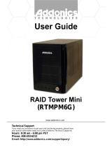
ERROR LED: glows red temporarily when power is first connected. Will glow red steadily to indicate an I/O
error occurred on the mSATA drive.
Activity LED: glows green to indicate an mSATA device in inserted and powered up, blinks to indicate
activity. Both Drive Activity LEDs will blink rapidly during a RAID 1 rebuild function.
HOST LED: glows green to indicate connection to SATA controller, blinks to indicate activity.
Drive Installation
Insert one or two mSATA media devices into the Drive connectors, at an angle, then press downward gently
until the drive snaps in place under the retaining clip.
Port Multiplier Compatibility
The Port Multiplier built into this device will only work with a Port Multiplier aware SATA host adapter when
configured as JBOD (individual drives). Identify your host controller and check with its hardware
manufacturer if you are unsure. Addonics offers several Port Multiplier aware host adapters. This
requirement does not apply to RAID Modes.
Hot Swapping
This device supports hot swapping (inserting or removing drives while the drives are running and connected
to a computer). The eSATA controller on the computer must also support hot swapping - be sure to confirm
this before attempting to insert or remove drives while the system is running. Also be sure to practice the
appropriate safe removal procedure before proceeding. Failure to practice safe removal procedures will
result in loss or corruption of data.
1www.addonics.com
Technical Support (M-F 8:30 am – 6:00 pm)
RAID Mode
Jumper Block
SATA
Connectors
Drive 1
Connector
Drive 2
Connector
Drive 2 Activity
and Error LEDs
Drive 1 Activity
and Error LEDs
HOST LED
SET Jumper
Retaining Clip
Setting Up the Adapter
The Dual mSATA – SATA Adapter is factory set for JBOD Mode. Each drive will be treated as an individual
target by the SATA controller, which is required to support Port Multipliers. RAID 0, RAID 1, and LARGE
Modes do not require port multiplier support.
The RAID Mode Jumper Block determines the mode when the adapter is powered up while the SET
Jumper's shunt is connected between SET and GND. To set the RAID Mode, arrange the two shunts on the
RAID Mode Jumper Block according to the table below, make sure the SET Jumper's shunt is connecting
SET and GND, then power up the adapter one time with a connection to a SATA controller. Once the
operating system shows the storage, the RAID Mode is configured.
After the RAID Mode has been set up correctly, the SET Jumper may be disabled by moving the shunt to
connect between SET and NC to prevent unintended configuration later.
NOTE: An existing RAID can only be changed to JBOD Mode. To change the type of RAID, you must first
delete the RAID by powering up the adapter with the jumpers set to JBOD Mode one time, then disconnect
power and set the desired RAID Mode afterward.
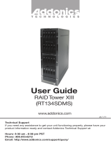
MODE JUMPER 1, 2, 3 JUMPER 4, 5, 6
JBOD (PM) 2-3 5-6
RAID 0 (R0) 1-2 4-5
RAID 1 (R1) 2-3 4-5
LARGE (SP) 1-2 5-6
Phone: 408-453-6212 Email: www.addonics.com/support/query/
2
The RAID Mode Jumper Block's pins are numbered as
shown here, with the board oriented component side up.
a M2 SSD
SATA
M2 SSD
is
. Move the mounting pole to the
location that matches the length of the M2. Secure the M2 to the mounting pole with the screw provided.
M2 SSD
/