Page is loading ...

User
Manual
Remote I/O
Scanner
(Cat.
No. 1747SN)
AllenBradley

Because of the variety of uses for the products described in this
publication, those responsible for the application and use of this
control equipment must satisfy themselves that all necessary steps
have been taken to assure that each application and use meets all
performance and safety requirements, including any applicable laws,
regulations, codes and standards.
The illustrations, charts, sample programs and layout examples
shown in this guide are intended solely for purposes of example.
Since there are many variables and requirements associated with any
particular installation, Allen-Bradley does not assume responsibility
or liability (to include intellectual property liability) for actual use
based upon the examples shown in this publication.
Allen-Bradley publication SGI-1.1, Safety Guidelines for the
Application, Installation, and Maintenance of Solid-State Control
(available from your local Allen-Bradley office), describes some
important differences between solid-state equipment and
electromechanical devices that should be taken into consideration
when applying products such as those described in this publication.
Reproduction of the contents of this copyrighted publication, in
whole or in part, without written permission of Allen-Bradley
Company, Inc., is prohibited.
Throughout this manual we use notes to make you aware of safety
considerations:
!
ATTENTION: Identifies information about practices
or circumstances that can lead to personal injury or
death, property damage or economic loss.
Attention statements help you to:
• identify a hazard
• avoid the hazard
• recognize the consequences
Important: Identifies information that is critical for successful
application and understanding of the product.
PLC is a registered trademark of the Allen-Bradley Company, Inc.
SLC, SLC 500, SLC 5/01, SLC 5/02, SLC 5/03, SLC 5/04, MicroLogix, PanelView, RediPANEL, Dataliner, PLC-5/15,
PLC-5/12, PLC-5/25, PLC-5/30, PLC-5/40, PLC-5/60 are trademarks of Allen-Bradley Company, Inc.
Important User
Information

Preface
Publication 17476.6 - July 1996
Preface
Read this preface to familiarize yourself with the rest of the manual.
This preface covers the following topics:
• who should use this manual
• the purpose of this manual
• conventions used in this manual
• Allen-Bradley support
Use this manual if you are responsible for designing, installing,
programming, or troubleshooting control systems that use
Allen-Bradley small logic controllers.
You should have a basic understanding of SLC 500t products. You
should understand programmable controllers and be able to interpret
the ladder logic instructions required to control your application. If
you do not, contact your local Allen-Bradley representative for
information on available training courses before using this product.
If using Advanced Programming Software (APS), we recommend
that you review The APS Quick Start for New Users, Publication
9399-APSQS, before you begin.
This manual is a reference guide for the Remote I/O (RIO) scanner.
It describes the procedures you use to install, configure, and operate
the 1747-SN RIO Scanner (Series B or later).
Who Should Use this
Manual
Purpose of this Manual

PrefaceP–2
Publication
17476.6 - July 1996
Contents of this Manual
Chapter Title Contents
Preface
Describes the purpose, background, and scope of
this manual. Also specifies the audience for whom
this manual is intended.
1 Overview
Contains the system overview, RIO network
overview, scanner/SLCt interaction, compatible
devices, and features.
2
Quick Start for
Experienced Users
Serves as a Quick Start Guide for the RIO scanner.
3 Installation and Wiring
Provides baud rate settings, installation
instructions, and wiring information.
4
Scanner Configuration
and Programming
Provides scanner configuration information, I/O file
information, and G and M file descriptions.
5 RIO Block Transfer
Describes RIO block transfer theory, M file block
transfer buffer layout, block transfer examples, and
how to set up block transfer operations.
6 Troubleshooting
Provides LED status information, troubleshooting
suggestions, and error codes.
7 Application Examples
Contains application examples for various system
configurations.
Appendix A Specifications
Contains scanner and system specifications, as
well as throughput information.
Appendix B M0-M1 Files and G Files
Contains general information and usage of M and
G files.
Appendix C
RIO Configuration
Worksheets
Contains blank worksheets for you to use when
configuring the scanner's I/O images.
Related Documentation
The following documents contain additional information concerning
Allen-Bradley SLC and PLCr products. To obtain a copy, contact
your local Allen-Bradley office or distributor.

Preface P–3
Publication
17476.6 - July 1996
For Read This Document
Document
Number
An overview of the SLC 500 family of products SLC 500 System Overview 17472.30
A description on how to install and use your Modular SLC 500
programmable controller
Installation & Operation Manual for Modular
Hardware Style Programmable Controllers
17476.2
A procedural manual for technical personnel who use APS to
develop control applications
Rockwell Software Advanced Programming
Software (APS) User Manual
9399APSUM
A reference manual that contains status file data and instruction set
information for the SLC 500 processors and MicroLogix 1000
controllers.
SLC 500t and MicroLogix 1000t Instruction Set
Reference Manual
17476.15
An introduction to APS for firsttime users, containing basic
concepts but focusing on simple tasks and exercises, and allowing
the reader to begin programming in the shortest time possible
APS Quick Start for New Users 9399APSQS
A training and quick reference guide to APS
SLC 500 Software Programmer's Quick Reference
Guideavailable on PASSPORT at a list price of
$50.00
ABT1747TSG001
A guide of common procedures used in APS.
SLC 500 Common Procedures Guideavailable on
PASSPORT at a list price of $50.00
ABT1747TSJ50
A procedural and reference manual for technical personnel who
use an HHT to develop control applications
AllenBradley HandHeld Terminal User Manual 1747NP002
An introduction to HHT for firsttime users, containing basic
concepts but focusing on simple tasks and exercises, and allowing
the reader to begin programming in the shortest time possible
Getting Started Guide for HHT 1747NM009
An article on wire sizes and types for grounding electrical
equipment
National Electrical Code
Published by the
National Fire
Protection
Association of
Boston, MA.
A complete listing of current AllenBradley documentation,
including ordering instructions. Also indicates whether the
documents are available on CDROM or in multilanguages.
AllenBradley Publication Index SD499
A glossary of industrial automation terms and abbreviations AllenBradley Industrial Automation Glossary AG7.1
The following conventions are used throughout this manual:
• Bulleted lists such as this one provide information, not procedural
steps.
• Numbered lists provide sequential steps or hierarchical
information.
• Italic type is used for emphasis.
• Text in this
font
indicates words or phrases you should type.
• Key names match the names shown and appear in bold, capital
letters within brackets (for example,
[ENTER]).
• A function key icon matches the name of the function key you
should press, such as
CONFIG
OFFLINE
CONFIG
SAVE &
EXIT
F8
.
We also use this convention to call attention to helpful information.
Common Techniques Used in
this Manual
"

PrefaceP–4
Publication
17476.6 - July 1996
Allen-Bradley offers support services worldwide, with over 75
Sales/Support Offices, 512 authorized Distributors and 260
authorized Systems Integrators located throughout the United States
alone, plus Allen-Bradley representatives in every major country in
the world.
Local Product Support
Contact your local Allen-Bradley representative for:
• sales and order support
• product technical training
• warranty support
• support service agreements
Technical Product Assistance
If you need to contact Allen-Bradley for technical assistance, please
review the information in the Troubleshooting chapter first. Then
call your local Allen-Bradley representative.
Your Questions or Comments on this Manual
If you find a problem with this manual, please notify us of it on the
enclosed Publication Problem Report.
If you have any suggestions for how this manual could be made
more useful to you, please contact us at the address below:
Allen-Bradley Company, Inc.
Automation Group
Technical Communication, Dept. 602V, T122
P.O. Box 2086
Milwaukee, WI 53201–2086
AllenBradley Support

Summary of Changes
Publication
17476.6 - July 1996
Summary of Changes
The information below summarizes the changes to this manual since
the last printing in February 1995.
To help you find new information and updated information in this
release of the manual, we have included change bars as shown to the
right of this paragraph.
The table below lists sections that document new features and
additional information about existing features, and shows where to
find this new information.
For This New Information See
CE Certification
chapter 3,
appendix A
Enhanced ladder logic programming examples chapter 5
New Information

Summary of Changes 1 . . . . . . . . . . . . . . . . . . . . . . . . . . . .
New
Information
1 . . . . . . . . . . . . . . . . . . . . . . . . . . . . . . . . . . . . .
Preface P-1 . . . . . . . . . . . . . . . . . . . . . . . . . . . . . . . . . . . . . . .
Who Should Use this Manual P-1 . . . . . . . . . . . . . . . . . . . . . . . . . . .
Purpose
of this Manual
P-1 . . . . . . . . . . . . . . . . . . . . . . . . . . . . . . . .
Contents
of this Manual
P-2 . . . . . . . . . . . . . . . . . . . . . . . . . . . . .
Related
Documentation
P-2 . . . . . . . . . . . . . . . . . . . . . . . . . . . . .
Common Techniques Used in this Manual P-3 . . . . . . . . . . . . . . . . . .
AllenBradley Support P-4 . . . . . . . . . . . . . . . . . . . . . . . . . . . . . . . .
Local Product Support P-4 . . . . . . . . . . . . . . . . . . . . . . . . . . . . . .
Technical Product Assistance P-4 . . . . . . . . . . . . . . . . . . . . . . . . .
Your Questions or Comments on this Manual P-4 . . . . . . . . . . . . . .
Overview 1-1 . . . . . . . . . . . . . . . . . . . . . . . . . . . . . . . . . . . . . .
System Overview 1-1 . . . . . . . . . . . . . . . . . . . . . . . . . . . . . . . . . . . .
Scanner
I/O Image Division
1-3 . . . . . . . . . . . . . . . . . . . . . . . . . . .
How the Scanner Scans Remote I/O 1-4 . . . . . . . . . . . . . . . . . . . . . .
SLC and Scanner Asynchronous Operation 1-5 . . . . . . . . . . . . . . .
How the Scanner Interacts with Adapters 1-6 . . . . . . . . . . . . . . . . . . .
Scanner
I/O Image Concepts
1-7 . . . . . . . . . . . . . . . . . . . . . . . . . . .
Example Scanner I/O Image 1-8 . . . . . . . . . . . . . . . . . . . . . . . . . .
Transferring Data with RIO Discrete and Block Transfers 1-9 . . . . . .
Physical and Logical RIO Link Specifications 1-9 . . . . . . . . . . . . . .
Extended
Node Capability
1-9 . . . . . . . . . . . . . . . . . . . . . . . . . . . .
Complementary
I/O
1-10 . . . . . . . . . . . . . . . . . . . . . . . . . . . . . . . .
Guidelines
for Configuring Complementary I/O
1-11 . . . . . . . . . . . . .
Complementary I/O: Placing Modules with 2Slot Addressing 1-12 . .
Complementary I/O: Placing Modules with 1Slot Addressing 1-13 . .
Complementary
I/O: Placing Modules with 1/2Slot Addressing
1-14 .
Summary for Placing Modules Used In Complementary I/O 1-15 . . . .
Discrete Modules 1-15 . . . . . . . . . . . . . . . . . . . . . . . . . . . . . . . . . .
Block Transfer Modules 1-15 . . . . . . . . . . . . . . . . . . . . . . . . . . . . .
Complementary
I/O Application Considerations
1-17 . . . . . . . . . . . . .
Complementary
1771 I/O Module Details
1-17 . . . . . . . . . . . . . . . . .
Hardware Features 1-18 . . . . . . . . . . . . . . . . . . . . . . . . . . . . . . . . . .
Baud
Rate DIP Switch
1-19 . . . . . . . . . . . . . . . . . . . . . . . . . . . . . .
LEDs 1-19 . . . . . . . . . . . . . . . . . . . . . . . . . . . . . . . . . . . . . . . . . .
RIO Link Connector 1-19 . . . . . . . . . . . . . . . . . . . . . . . . . . . . . . . .
Compatible Devices 1-20 . . . . . . . . . . . . . . . . . . . . . . . . . . . . . . . .
Table of Contents

Table of Contentsii
Quick Start for Experienced Users 2-1 . . . . . . . . . . . . . . . . . . .
Required Tools and Equipment 2-1 . . . . . . . . . . . . . . . . . . . . . . . . . .
Procedures 2-2 . . . . . . . . . . . . . . . . . . . . . . . . . . . . . . . . . . . . . . . .
Installation and Wiring 3-1 . . . . . . . . . . . . . . . . . . . . . . . . . . . .
Compliance to European Union Directives 3-1 . . . . . . . . . . . . . . . . . .
EMC Directive 3-1 . . . . . . . . . . . . . . . . . . . . . . . . . . . . . . . . . . . .
Baud
Rate Selection
3-2 . . . . . . . . . . . . . . . . . . . . . . . . . . . . . . . . . .
Scanner
Installation
3-3 . . . . . . . . . . . . . . . . . . . . . . . . . . . . . . . . . .
Insertion 3-3 . . . . . . . . . . . . . . . . . . . . . . . . . . . . . . . . . . . . . . . .
Removal 3-4 . . . . . . . . . . . . . . . . . . . . . . . . . . . . . . . . . . . . . . . .
RIO Link Wiring 3-4 . . . . . . . . . . . . . . . . . . . . . . . . . . . . . . . . . . . . .
Start Up 3-6 . . . . . . . . . . . . . . . . . . . . . . . . . . . . . . . . . . . . . . . . . .
Scanner Operation 3-7 . . . . . . . . . . . . . . . . . . . . . . . . . . . . . . . . . . .
At Power Up 3-7 . . . . . . . . . . . . . . . . . . . . . . . . . . . . . . . . . . . . .
In Run Mode 3-7 . . . . . . . . . . . . . . . . . . . . . . . . . . . . . . . . . . . . .
When Changing From Run Mode 3-7 . . . . . . . . . . . . . . . . . . . . . .
Status LEDs 3-8 . . . . . . . . . . . . . . . . . . . . . . . . . . . . . . . . . . . . . . .
Scanner Configuration and Programming 4-1 . . . . . . . . . . . . .
Understanding
Remote Input and Output Image Files
4-1 . . . . . . . . . .
RIO
Configuration Using G Files
4-3 . . . . . . . . . . . . . . . . . . . . . . . . .
Rules for Configuring the Scanner 4-5 . . . . . . . . . . . . . . . . . . . . . .
General 4-5 . . . . . . . . . . . . . . . . . . . . . . . . . . . . . . . . . . . . . . . . .
Concerning
Complementary I/O
4-5 . . . . . . . . . . . . . . . . . . . . . . . .
Example G File Showing Primary and Complementary Device
Configurations 4-6 . . . . . . . . . . . . . . . . . . . . . . . . . . . . . . . . .
Illegal Configuration Examples 4-7 . . . . . . . . . . . . . . . . . . . . . . . .
Example Scanner Input Image of the Primary Devices 4-8 . . . . . . . .
Example Scanner Input Image of the Complementary Devices 4-9 . .
Considerations When Configuring Remote I/O 4-10 . . . . . . . . . . . . . . .
G File Considerations 4-10 . . . . . . . . . . . . . . . . . . . . . . . . . . . . . . .
Crossing Logical Rack Boundaries 4-10 . . . . . . . . . . . . . . . . . . . . .
Examples of Crossing Logical Rack Boundaries 4-10 . . . . . . . . . . . .
Creating More than One Logical Rack Device 4-11 . . . . . . . . . . . . . .
Understanding
M Files
4-12 . . . . . . . . . . . . . . . . . . . . . . . . . . . . . . . .
M0 Control File Description 4-14 . . . . . . . . . . . . . . . . . . . . . . . . . . .
M0
File - RIO Device Inhibit Control
4-15 . . . . . . . . . . . . . . . . . . . . .
Example
of Device Inhibit Control
4-15 . . . . . . . . . . . . . . . . . . . . . .
M0
File - RIO Device Reset Control
4-16 . . . . . . . . . . . . . . . . . . . . .
Example of Device Reset Control 4-16 . . . . . . . . . . . . . . . . . . . . . .
M0
File - Remote Output Reset Control
4-17 . . . . . . . . . . . . . . . . . .
Example
of Remote Output Reset Control
4-18 . . . . . . . . . . . . . . . .
Device Reset and Remote Output Reset Considerations 4-19 . . . . . . . .
M1
Status File Description
4-21 . . . . . . . . . . . . . . . . . . . . . . . . . . . . .

Table of Contents iii
General
Communication Status - Enable Device Fault Bit
4-21 . . . . .
General
Communication Status - Communication Attempted Bit
4-22 .
RIO Baud Rate Status 4-22 . . . . . . . . . . . . . . . . . . . . . . . . . . . . . .
Logical Device Starting Address Status 4-23 . . . . . . . . . . . . . . . . . .
Logical Device Image Size Status 4-24 . . . . . . . . . . . . . . . . . . . . . .
Active Device Status 4-24 . . . . . . . . . . . . . . . . . . . . . . . . . . . . . . . .
Logical
Device Fault Status
4-26 . . . . . . . . . . . . . . . . . . . . . . . . . . .
RIO
Status Example
4-27 . . . . . . . . . . . . . . . . . . . . . . . . . . . . . . . .
RIO Communication Retry Counter (M1:e.16 47) 4-29 . . . . . . . . . . . .
Retry Counter Example for Primary Devices 4-29 . . . . . . . . . . . . . . .
Understanding Slot Addressing 4-31 . . . . . . . . . . . . . . . . . . . . . . . . . .
SLC/Scanner
Configuration
4-32 . . . . . . . . . . . . . . . . . . . . . . . . . . . . .
RIO Block Transfer 5-1 . . . . . . . . . . . . . . . . . . . . . . . . . . . . . .
RIO Block Transfer Theory of Operation 5-1 . . . . . . . . . . . . . . . . . . . .
What
Is RIO Block T
ransfer? 5-1 . . . . . . . . . . . . . . . . . . . . . . . . . .
RIO Block Transfer General Functional Overview 5-5 . . . . . . . . . . . . .
Scanner
I/O Image Allocation For Block T
ransfer 5-6 . . . . . . . . . . .
Examples
of BT I/O Image File Allocation
5-6 . . . . . . . . . . . . . . . . .
Scanner's Block Transfer Buffer Layout 5-8 . . . . . . . . . . . . . . . . . . . .
M0 File - Block Transfer Output/Control Buffers 5-8 . . . . . . . . . . . .
M0
File BT Control Buf
fer Layout 5-9 . . . . . . . . . . . . . . . . . . . . . . .
BT
Control Flag Definitions
5-9 . . . . . . . . . . . . . . . . . . . . . . . . . . .
M1 File - Block Transfer Input/Status Buffers 5-10 . . . . . . . . . . . . . .
M1
File - Input/Status BT Buf
fer Layout
(M1:e.100 ... M1:e.3200)
5-11 . . . . . . . . . . . . . . . . . . . . . . . . . .
M1 File - BTR/BTW Error Codes
(M1:e.103 ... M1:e.3203)
5-11 . . . . . . . . . . . . . . . . . . . . . . . . . .
M1
File - BTR/BTW Status Flag Definitions
(M1:e.100 ... M1:e.3200)
5-12 . . . . . . . . . . . . . . . . . . . . . . . . . .
Detailed Operation of RIO Block Transfer 5-13 . . . . . . . . . . . . . . . . . . .
Block Transfer T
iming Diagrams
5-14 . . . . . . . . . . . . . . . . . . . . . . .
Successful Block Transfer Read/Write 5-15 . . . . . . . . . . . . . . . . . . .
Block Transfer Failure at Startup 5-16 . . . . . . . . . . . . . . . . . . . . . . .
Block Transfer Failure after Startup of Transmission
Across the RIO Link 5-17 . . . . . . . . . . . . . . . . . . . . . . . . . . . . .
SLC Control Program Canceling a BT Once T
ransmitted
Across RIO Link 5-18 . . . . . . . . . . . . . . . . . . . . . . . . . . . . . . . .
SLC Control Program Canceling a BT Prior to Transmission
Across RIO Link 5-19 . . . . . . . . . . . . . . . . . . . . . . . . . . . . . . . .
RIO Block Transfer Application Considerations 5-20 . . . . . . . . . . . . . . .
Setting Up a Block Transfer 5-21 . . . . . . . . . . . . . . . . . . . . . . . . . . . . .
Quick Reference to Status and Control Bits 5-22 . . . . . . . . . . . . . . . . .
Status
Bits
5-22 . . . . . . . . . . . . . . . . . . . . . . . . . . . . . . . . . . . . . . .
Control
Bits
5-22 . . . . . . . . . . . . . . . . . . . . . . . . . . . . . . . . . . . . . .
BTR and BTW Control Logic Examples 5-23 . . . . . . . . . . . . . . . . . . . .

Table of Contentsiv
Block Transfer Read Control Logic Example 5-23 . . . . . . . . . . . . . . .
Block Transfer Write Control Logic Example 5-25 . . . . . . . . . . . . . . .
Directional Continuous Block Transfer Example 5-29 . . . . . . . . . . . .
Directional Repeating Block Transfer Example 5-32 . . . . . . . . . . . . .
Directional NonContinuous Block Transfer Example 5-35 . . . . . . . . .
Bidirectional Continuous Block Transfer Example 5-38 . . . . . . . . . . .
Bidirectional Alternating Block Transfer 5-43 . . . . . . . . . . . . . . . . . .
Bidirectional Alternating Repeating Block Transfer 5-49 . . . . . . . . . . .
Troubleshooting 6-1 . . . . . . . . . . . . . . . . . . . . . . . . . . . . . . . .
Troubleshooting 6-1 . . . . . . . . . . . . . . . . . . . . . . . . . . . . . . . . . . . . .
Error Codes 6-2 . . . . . . . . . . . . . . . . . . . . . . . . . . . . . . . . . . . . . . . .
Retry Counters 6-2 . . . . . . . . . . . . . . . . . . . . . . . . . . . . . . . . . . . . .
Block Transfers 6-2 . . . . . . . . . . . . . . . . . . . . . . . . . . . . . . . . . . . . .
Application Examples 7-1 . . . . . . . . . . . . . . . . . . . . . . . . . . . .
RediPANEL Keypad Module 7-1 . . . . . . . . . . . . . . . . . . . . . . . . . . . .
Scanner
Configuration
7-3 . . . . . . . . . . . . . . . . . . . . . . . . . . . . . .
Example Program 7-3 . . . . . . . . . . . . . . . . . . . . . . . . . . . . . . . . .
RediPANEL/DCM 7-4 . . . . . . . . . . . . . . . . . . . . . . . . . . . . . . . . . . . .
Scanner
Configuration
7-6 . . . . . . . . . . . . . . . . . . . . . . . . . . . . . .
Example Program 7-6 . . . . . . . . . . . . . . . . . . . . . . . . . . . . . . . . .
Dataliner 7-8 . . . . . . . . . . . . . . . . . . . . . . . . . . . . . . . . . . . . . . . . . .
Scanner
Configuration
7-10 . . . . . . . . . . . . . . . . . . . . . . . . . . . . . .
Example Program 7-10 . . . . . . . . . . . . . . . . . . . . . . . . . . . . . . . . .
PanelView 7-11 . . . . . . . . . . . . . . . . . . . . . . . . . . . . . . . . . . . . . . . . .
Scanner
Configuration
7-13 . . . . . . . . . . . . . . . . . . . . . . . . . . . . . .
Example Program 7-13 . . . . . . . . . . . . . . . . . . . . . . . . . . . . . . . . .
Block Transfer Application Example 7-14 . . . . . . . . . . . . . . . . . . . . . . .
Scanner
Configuration
7-14 . . . . . . . . . . . . . . . . . . . . . . . . . . . . . .
System Layout Diagram 7-16 . . . . . . . . . . . . . . . . . . . . . . . . . . . . .
Example Program 7-16 . . . . . . . . . . . . . . . . . . . . . . . . . . . . . . . . .
Specifications A-1 . . . . . . . . . . . . . . . . . . . . . . . . . . . . . . . . . .
Scanner Operating Specifications A-1 . . . . . . . . . . . . . . . . . . . . . . . .
Network
Specifications
A-1 . . . . . . . . . . . . . . . . . . . . . . . . . . . . . . . .
Throughput Introduction A-2 . . . . . . . . . . . . . . . . . . . . . . . . . . . . . . .
RIO Network Throughput Components A-2 . . . . . . . . . . . . . . . . . . .
Calculating Throughput A-3 . . . . . . . . . . . . . . . . . . . . . . . . . . . . . . . .
Discrete I/O Throughput without Block Transfers
(Tdm-nbt) Present A-3 . . . . . . . . . . . . . . . . . . . . . . . . . . . . . .
RIO Scan T
ime Calculation (TRIO)
A-4 . . . . . . . . . . . . . . . . . . . . .
Example Discrete I/O Throughput without Block Transfers
Present A-4 . . . . . . . . . . . . . . . . . . . . . . . . . . . . . . . . . . . . . .
Discrete I/O Throughput with Block Transfers (Tdm-bt) Present A-6 .

Table of Contents v
Determining TSNo-bt A-7 . . . . . . . . . . . . . . . . . . . . . . . . . . . . . . .
Determining Tbtx A-7 . . . . . . . . . . . . . . . . . . . . . . . . . . . . . . . . . .
Example Discrete I/O Throughput with Block Transfers Present A-8 .
Block Transfer Throughput A-10 . . . . . . . . . . . . . . . . . . . . . . . . . . .
RIO Scanner Output Delay Time (TSNo) Tables A-11 . . . . . . . . . . . .
Determining the Number of Logical Racks Configured A-12 . . . . . . . .
TSNo
without M0 File W
rites A-13 . . . . . . . . . . . . . . . . . . . . . . . . . .
TSNo
with M0 File W
rites (No Block Transfers) A-13 . . . . . . . . . . . . .
M0-M1 Files and G Files B-1 . . . . . . . . . . . . . . . . . . . . . . . . . .
M0-M1
Files
B-1 . . . . . . . . . . . . . . . . . . . . . . . . . . . . . . . . . . . . . . .
Configuring M0-M1 Files Using APS Software B-1 . . . . . . . . . . . . .
Addressing
M0-M1 Files
B-2 . . . . . . . . . . . . . . . . . . . . . . . . . . . .
Restrictions on Using M0M1 Data File Addresses B-2 . . . . . . . . . .
Monitoring Bit Addresses B-3 . . . . . . . . . . . . . . . . . . . . . . . . . . . .
M0/M1
Monitoring Option Disabled
B-3 . . . . . . . . . . . . . . . . . . . . .
M0/M1
Monitoring Option Enabled
B-4 . . . . . . . . . . . . . . . . . . . . . .
Transferring Data Between Processor Files and M0 or M1 Files B-4 .
Access Time B-5 . . . . . . . . . . . . . . . . . . . . . . . . . . . . . . . . . . . . .
SLC 5/02 Processor Example B-5 . . . . . . . . . . . . . . . . . . . . . . . . .
SLC 5/03 Processor Example B-6 . . . . . . . . . . . . . . . . . . . . . . . . .
SLC 5/04 Processor Example B-6 . . . . . . . . . . . . . . . . . . . . . . . . .
Minimizing the Scan Time B-7 . . . . . . . . . . . . . . . . . . . . . . . . . . . .
Capturing
M0-M1 File Data
B-8 . . . . . . . . . . . . . . . . . . . . . . . . . . .
Specialty
I/O Modules with Retentive Memory
B-8 . . . . . . . . . . . . . .
G
Files
B-9 . . . . . . . . . . . . . . . . . . . . . . . . . . . . . . . . . . . . . . . . . . .
Configuring G Files Using APS Software B-9 . . . . . . . . . . . . . . . . .
Editing
G File Data
B-11 . . . . . . . . . . . . . . . . . . . . . . . . . . . . . . . . .
RIO Configuration Worksheet C-1 . . . . . . . . . . . . . . . . . . . . . .
Directions C-1 . . . . . . . . . . . . . . . . . . . . . . . . . . . . . . . . . . . . . . . . .
Glossary G-1 . . . . . . . . . . . . . . . . . . . . . . . . . . . . . . . . . . . . . .

Chapter 1
Publication
17476.6 - July 1996
Overview
This chapter contains the following information:
• system overview
• how the scanner interacts with the SLC processor
• how the scanner interacts with adapter modules
• scanner I/O image concepts
• extended node capability
• complementary I/O
• scanner features
• compatible network devices
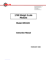
The Remote I/O (RIO) scanner, Catalog Number 1747-SN, is the
remote I/O scanner for the SLC 500. It enables communication
between an SLC processor (SLC 5/02t or later) and remotely
located (3,048 meters [10,000 feet] maximum) 1746 I/O chassis and
other RIO compatible Allen-Bradley operator interface and control
devices. The 1747-SN scanner communicates with remotely located
devices using the A-B Remote I/O link. The RIO link consists of a
single master (scanner) and multiple slaves (adapters).
Communication between devices occurs over twisted pair cable with
the devices daisy-chained together. The scanner can reside in any
slot of the local SLC chassis except for slot 0.
The scanner transfers input and
output data between itself and all
configured network devices over
twisted pair cable. Note that the
endtoend length of the cable can be
a maximum of 3,048 meters (10,000
feet).
Datalinert Message Display
(Adapter/Slave)
PanelViewt Operator Terminal
(Adapter/Slave)
SLC 5/02
or Later
Processor
Remote Chassis
Remote Expansion Chassis
1747ASB Module
(Adapter/Slave)
RediPANELt
(Adapter/Slave)
Local SLC Chassis
RIO Scanner
(Master of the
RIO Link)
System Overview

1–2 Overview
Publication
17476.6 - July 1996
The scanner can be configured for and transfer a maximum of 4
logical racks of discrete data on the RIO link. The scanner provides
discrete I/O and block (Series B or later) transfers. Configurations
allowed are any combination of quarter, half, three quarter, or full
logical rack devices.
The scanner transfers discrete input and output data
between itself, remote adapters, and the SLC processor.
Remote adapters consist of 1746 chassis and other
AllenBradley operator interface and control devices.
RIO
Scanner
SLC 5/02
or Later
Processor
Quarter Logical
Rack
Device
Half
Logical Rack
Device
Three Quarter
Logical Rack
Device
Full
Logical Rack
Device
Half Logical
Rack
Device
Full
Logical Rack
Device
Adapter 1
Adapter 2
Adapter 3 Adapter 4
Adapter 5
Adapter 6
The SLC processor transfers the scanner’s 4 logical racks (32 input
image and 32 output image words) of discrete remote I/O image data
into the SLC input and output image files. You can adjust the size of
the scanner input and output image file during configuration of your
SLC system so that the scanner only transfers the discrete I/O data
your application program requires. Configuration is done through
the confiGuration file (G file). Refer to chapter 4, Configuration and
Programming for more information.
Important: The SLC 500 processor (SLC 5/02 or later) supports
multiple scanners in its local I/O chassis. The
maximum number is dependent on the following:
• backplane power requirements (power supply dependent)
• SLC 500 processor I/O data table limit (4,096 I/O)
• processor memory to support the application (SLC 500 processor
dependent)

1–3Overview
Publication
17476.6 - July 1996
Scanner I/O Image Division
The scanner allows each adapter to use a fixed amount (user defined)
of the scanner’s input and output image. Part of the SLC processor’s
image is used by local I/O, the other portion is used by the scanner
for remote I/O.
The scanner remote I/O image is divided into logical racks and
further divided into logical groups. A full logical rack consists of
eight input and eight output image words. A logical group consists
of one input and one output word in a logical rack. Each logical
group is assigned a number from 0–7.
Processor I/O Image Scanner I/O Image Adapter
Image
Logical
Group 7
Local I/O
Remote I/O
(Scanner Image)
Logical
Rack 2
Logical Rack 1
Logical Rack 0
Logical Group 0
The scanner image contains the image of each adapter on the RIO
link. The adapter is assigned a portion of the scanner image, which
is referred to as the adapter image.

1–4 Overview
Publication
17476.6 - July 1996
The scanner communicates with each logical device in a sequential
fashion. First, the scanner initiates communication with a device by
sending output data to the device. The device then responds by
sending its input data back to the scanner, as illustrated below. You
refer to this exchange as a discrete I/O transfer. After the scanner
completes its discrete I/O transfer with the last configured network
device, it begins another discrete I/O transfer with the first device.
It is important to understand that the scanner transfers RIO data on a
logical device basis not on an adapter basis. A logical device is a
full logical rack or portion of a logical rack assigned to an adapter.
RIO Scanner Scan
Scanner Output
Image File
The scanner updates its
input image file each time
it scans a logical device.
Output
Device 3
Output
Device 2
Output
Device 1
Input
Device 3
Input
Device 2
Input
Device 1
Scanner
Input
Image File
How the Scanner Scans
Remote I/O

1–5Overview
Publication
17476.6 - July 1996
SLC and Scanner Asynchronous Operation
The SLC processor scan and RIO scanner scan are independent
(asynchronous) of each other. The SLC processor reads the scanner
input image file during its input scan and writes the output image file
to the scanner during its output scan. The RIO scanner continues
reading inputs and writing outputs to the scanner I/O image file,
independent of the SLC processor scan cycle.
Depending on your SLC processor, RIO link configuration, and
application program size, the scanner may complete multiple scans
before the SLC processor reads the scanner’s input image file. The
RIO scanner updates its I/O files on a per logical rack basis.
The figure below illustrates the asynchronous operation of the SLC
processor and RIO scanner.
SLC Processor
SLC Processor Scan Cycle RIO Scanner Scan Cycle
Program
The scanner updates its
input image file each time
it scans a logical device.
The scanner may scan all
of its configured logical
devices several times
before the SLC processor
reads the scanner's input
image file.
The SLC processor reads the
scanner input image file into the
SLC input image file, processes
it, and creates an SLC output
image file. The SLC processor
transfers its output file to the
scanner.
SLC Input
Image File
SLC Output
Image File
Scanner
Input
Image File
Scanner Output
Image File
Output
Image
Device 3
Output
Image
Device 2
Output
Image
Device 1
Input
Image
Device 3
Input
Image
Device 2
Input
Image
Device 1
Important: The outputs of the RIO are updated after the end of the first SLC processor scan.

1–6 Overview
Publication
17476.6 - July 1996
The scanner’s function is to continuously scan the adapters on the
RIO link in a consecutive manner. This scan consists of one or more
RIO discrete transfers to each adapter on the RIO link.
RIO discrete transfers consist of the scanner sending output image
data and communication commands to the adapter that instruct the
adapter on how to control its output. (These include run, adapter
reset, and reset decide commands.) The adapter responds by sending
input data to the scanner. The scanner performs as many RIO
discrete transfers as necessary to update the entire adapter image. If
RIO discrete transfers do not occur, data is not exchanged between
the scanner and adapter. RIO discrete transfers are asynchronous to
the processor scan.
RediPANEL
PanelView Operator
Terminal
SLC Local Chassis
Scanner
Processor
RIO Discrete
Transfers
with Adapter 1
RIO Discrete
Transfers
with Adapter 2
RIO Discrete
Transfers
with Adapter 3
RIO Discrete
Transfers
with Adapter 4
How the Scanner Interacts
with Adapters

1–7Overview
Publication
17476.6 - July 1996
The scanner’s I/O image consists of RIO logical racks and I/O
groups. A full RIO logical rack consists of eight input image and
eight output image words. (A word consists of 16 bits of data.) Each
word within an RIO logical rack is assigned an I/O group number
from 0 to 7.
You assign devices on the RIO link a portion of the scanner’s image.
Devices can occupy a quarter logical rack (2 input and output
words), half logical rack (4 I/O words), three quarter logical rack (6
I/O words), or full logical rack. You may configure devices to start
at any even I/O group number within an RIO logical rack. More
than one physical device’s (adapter) I/O information can reside in a
single logical rack. Also, by crossing logical rack boundaries a
device can consist of more than one logical rack.
Important: The illustration below shows only the input image
configuration of the scanner’s I/O image. The output
image configuration is the same.
Rack 3 Group 6
Rack 3 Group 7
Rack 1 Group 2
Rack 1 Group 3
Rack 1 Group 0
Rack 1 Group 1
Rack 1 Group 6
Rack 1 Group 4
Rack 1 Group 5
Rack 0 Group 6
Rack 0 Group 7
Rack 0 Group 4
Rack 0 Group 5
Rack 0 Group 2
Rack 0 Group 3
0123456789101112131415
Bit Number (decimal)
Word 0
Word 1
Word 2
Word 3
Word 4
Word 7
Word 8
Word 9
Word 10
Word 11
Word 12
Word 13
Word 14
Word 5
Word 6
Word 30
Word 31
Rack 0 Group 0
Rack 0 Group 1
Rack 3 Group 1
Rack 3 Group 2
Rack 2 Group 7
Rack 3 Group 0
Rack 3 Group 5
Rack 3 Group 3
Rack 3 Group 4
Rack 2 Group 5
Rack 2 Group 6
Rack 2 Group 3
Rack 2 Group 4
Rack 2 Group 1
Rack 2 Group 2
Word 15
Word 16
Word 17
Word 18
Word 19
Word 22
Word 23
Word 24
Word 25
Word 26
Word 27
Word 28
Word 29
Word 20
Word 21
Rack 1 Group 7
Rack 2 Group 0
RIO
Logical
Rack 0
0
8
1
8
2
8
3
8
4
8
5
8
6
8
7
8
10
8
11
8
12
8
13
8
14
8
15
8
16
8
17
8
Bit Number (octal)
RIO
Logical
Rack 1
RIO
Logical
Rack 2
RIO
Logical
Rack 3
Quarter Logical
Rack
Half Logical
Rack
Three Quarter
Logical Rack
Full
Logical
Rack
Input Image Half of a Scanner's I/O Image
Not Used In This
Example
Not Used In This
Example
Not Used In This
Example
Scanner I/O Image
Concepts

1–8 Overview
Publication
17476.6 - July 1996
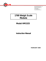
Example Scanner I/O Image
The illustrations below show a scanner’s input image of 4 RIO link
devices.
RIO
Scanner
SLC 5/02
or Later
Processor
Three Quarter Logical
Rack Device
Begins at Logical
Rack 1, Group 0.
Half Logical Rack
Device
Begins at Logical
Rack 2, Group 0.
Quarter Logical Rack
Device
Begins at Logical
Rack 2, Group 4.
Full Logical Rack
Device
Begins at Logical
Rack 0, Group 0.
Device 1
Device 2
Device 3 Device 4
Rack 3 Group 6
Rack 3 Group 7
Rack 1 Group 2
Rack 1 Group 3
Rack 1 Group 0
Rack 1 Group 1
Rack 1 Group 6
Rack 1 Group 4
Rack 1 Group 5
Rack 0 Group 6
Rack 0 Group 7
Rack 0 Group 4
Rack 0 Group 5
Rack 0 Group 2
Rack 0 Group 3
0123456789101112131415
Bit Number
Input File
Address
I:e.0
I:e.1
I:e.2
I:e.3
I:e.4
I:e.5
I:e.6
I:e.7
I:e.8
I:e.9
I:e.10
I:e.11
I:e.12
I:e.13
I:e.14
I:e.30
I:e.31
Word
0
Word 1
Word 2
Word 3
Word 4
Word 7
Word 8
Word 9
Word 10
Word 11
Word 12
Word 13
Word 14
Word 5
Word 6
Word 30
Word 31
Rack 0 Group 0
Rack 0 Group 1
Rack 3 Group 1
Rack 3 Group 2
Rack 2 Group 7
Rack 3 Group 0
Rack 3 Group 5
Rack 3 Group 3
Rack 3 Group 4
Rack 2 Group 5
Rack 2 Group 6
Rack 2 Group 3
Rack 2 Group 4
Rack 2 Group 1
Rack 2 Group 2
I:e.15
I:e.16
I:e.17
I:e.18
I:e.19
I:e.20
I:e.21
I:e.22
I:e.23
I:e.24
I:e.25
I:e.26
I:e.27
I:e.28
I:e.29
Word 15
Word 16
Word 17
Word 18
Word 19
Word 22
Word 23
Word 24
Word 25
Word 26
Word 27
Word 28
Word 29
Word 20
Word 21
Rack 1 Group 7
Rack 2 Group 0
RIO
Logical
Rack 0
Device 1
Device 2
Device 3
Device 4
e = slot number of the SLC chassis containing the scanner
0
8
1
8
2
8
3
8
4
8
5
8
6
8
7
8
10
8
11
8
12
8
13
8
14
8
15
8
16
8
17
8
Bit Number (octal)
RIO
Logical
Rack 1
RIO
Logical
Rack 2
RIO
Logical
Rack 3
Important: The illustration below shows only the scanner's input image. The output image looks the same.
Not
Used
Not Used
/