Page is loading ...

PanelView Plus
Terminals
2711P
(400, 600, 700, 1000, 1250, 1500)
User Manual

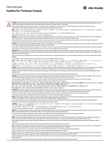
Important User Information
Solid state equipment has operational characteristics differing from those of
electromechanical equipment. Safety Guidelines for the Application,
Installation and Maintenance of Solid State Controls (Publication SGI-1.1
available from your local Rockwell Automation sales office or online at
http://www.ab.com/manuals/gi) describes some important differences
between solid state equipment and hard-wired electromechanical devices.
Because of this difference, and also because of the wide variety of uses for
solid state equipment, all persons responsible for applying this equipment
must satisfy themselves that each intended application of this equipment is
acceptable.
In no event will Rockwell Automation, Inc. be responsible or liable for
indirect or consequential damages resulting from the use or application of
this equipment.
The examples and diagrams in this manual are included solely for illustrative
purposes. Because of the many variables and requirements associated with
any particular installation, Rockwell Automation, Inc. cannot assume
responsibility or liability for actual use based on the examples and diagrams.
No patent liability is assumed by Rockwell Automation, Inc. with respect to
use of information, circuits, equipment, or software described in this manual.
Reproduction of the contents of this manual, in whole or in part, without
written permission of Rockwell Automation, Inc. is prohibited.
Throughout this manual, when necessary we use notes to make you aware of
safety considerations.
WARNING
Identifies information about practices or circumstances
that can cause an explosion in a hazardous environment,
which may lead to personal injury or death, property
damage, or economic loss.
IMPORTANT
Identifies information that is critical for successful
application and understanding of the product.
ATTENTION
Identifies information about practices or circumstances
that can lead to personal injury or death, property
damage, or economic loss. Attentions help you:
• identify a hazard
• avoid a hazard
• recognize the consequence
SHOCK HAZARD
Labels may be located on or inside the equipment (e.g.,
drive or motor) to alert people that dangerous voltage may
be present.
BURN HAZARD
Labels may be located on or inside the equipment (e.g.,
drive or motor) to alert people that surfaces may be at
dangerous temperatures.

i Publication 2711P-UM001D-EN-P - September 2005
Table of Contents
Preface
Objectives. . . . . . . . . . . . . . . . . . . . . . . . . . . . . . . . . Preface-i
Parts List. . . . . . . . . . . . . . . . . . . . . . . . . . . . . . . . . . Preface-i
Intended Audience . . . . . . . . . . . . . . . . . . . . . . . . . . Preface-i
Manual Contents . . . . . . . . . . . . . . . . . . . . . . . . . . . . Preface-ii
Additional Resources. . . . . . . . . . . . . . . . . . . . . . . . Preface-iii
Software and Firmware Upgrades . . . . . . . . . . . . . . Preface-iii
European Communities (EC) Directive Compliance . Preface-iv
Chapter 1
Overview
Chapter Objectives . . . . . . . . . . . . . . . . . . . . . . . . . . . . . . 1-1
Software Support . . . . . . . . . . . . . . . . . . . . . . . . . . . . . . . 1-1
PanelView Plus 400 and 600 Features . . . . . . . . . . . . . . . . 1-2
PanelView Plus 700 - 1500 Features . . . . . . . . . . . . . . . . . . 1-7
Catalog Number Configuration. . . . . . . . . . . . . . . . . . . . . . 1-12
PanelView Plus Product Components. . . . . . . . . . . . . . . . . 1-12
Chapter 2
Installation
Chapter Objectives . . . . . . . . . . . . . . . . . . . . . . . . . . . . . . 2-1
Hazardous Locations . . . . . . . . . . . . . . . . . . . . . . . . . . . . . 2-1
Environmental Considerations . . . . . . . . . . . . . . . . . . . . . . 2-3
Enclosures . . . . . . . . . . . . . . . . . . . . . . . . . . . . . . . . . . . . 2-3
Outdoor Installation (cat. no. 2711P-RDT12H only) . . . . . . 2-4
Required Tools . . . . . . . . . . . . . . . . . . . . . . . . . . . . . . . . . 2-5
Clearances . . . . . . . . . . . . . . . . . . . . . . . . . . . . . . . . . . . . 2-5
Panel Cutout Dimensions . . . . . . . . . . . . . . . . . . . . . . . . . 2-5
Mount the 400 or 600 Terminal in a Panel . . . . . . . . . . . . . 2-6
Mount the 700-1500 Terminal in a Panel . . . . . . . . . . . . . . 2-8
Product Dimensions . . . . . . . . . . . . . . . . . . . . . . . . . . . . . 2-10
Chapter 3
Connect Power
Chapter Objectives . . . . . . . . . . . . . . . . . . . . . . . . . . . . . . 3-1
Wiring and Safety Guidelines. . . . . . . . . . . . . . . . . . . . . . . 3-1
Remove and Install the Power Terminal Block . . . . . . . . . . 3-2
DC Power Connections . . . . . . . . . . . . . . . . . . . . . . . . . . . 3-4
AC Power Connections . . . . . . . . . . . . . . . . . . . . . . . . . . . 3-7
Reset the Terminal . . . . . . . . . . . . . . . . . . . . . . . . . . . . . . 3-9
Startup Sequence . . . . . . . . . . . . . . . . . . . . . . . . . . . . . . . 3-11
Chapter 4
Configuration Mode
Chapter Objectives . . . . . . . . . . . . . . . . . . . . . . . . . . . . . . 4-1
Start Configuration Mode. . . . . . . . . . . . . . . . . . . . . . . . . . 4-1
Load an ME Application . . . . . . . . . . . . . . . . . . . . . . . . . . 4-4
Run an Application . . . . . . . . . . . . . . . . . . . . . . . . . . . . . . 4-5
Application Settings. . . . . . . . . . . . . . . . . . . . . . . . . . . . . . 4-5

Publication 2711P-UM001D-EN-P - September 2005
Table of Contents ii
Terminal Settings . . . . . . . . . . . . . . . . . . . . . . . . . . . . . . . 4-5
Networks and Communications . . . . . . . . . . . . . . . . . . . . . 4-6
Diagnostic Setup . . . . . . . . . . . . . . . . . . . . . . . . . . . . . . . . 4-16
File Management. . . . . . . . . . . . . . . . . . . . . . . . . . . . . . . . 4-17
Display. . . . . . . . . . . . . . . . . . . . . . . . . . . . . . . . . . . . . . . 4-20
Font Linking . . . . . . . . . . . . . . . . . . . . . . . . . . . . . . . . . . . 4-23
Input Devices . . . . . . . . . . . . . . . . . . . . . . . . . . . . . . . . . . 4-24
Print Setup . . . . . . . . . . . . . . . . . . . . . . . . . . . . . . . . . . . . 4-28
Startup Options. . . . . . . . . . . . . . . . . . . . . . . . . . . . . . . . . 4-30
System Event Log . . . . . . . . . . . . . . . . . . . . . . . . . . . . . . . 4-34
System Information . . . . . . . . . . . . . . . . . . . . . . . . . . . . . . 4-35
Time/Date/Regional Settings . . . . . . . . . . . . . . . . . . . . . . . 4-38
Chapter 5
Install and Replace Components
Chapter Objectives . . . . . . . . . . . . . . . . . . . . . . . . . . . . . . 5-1
Required Tools . . . . . . . . . . . . . . . . . . . . . . . . . . . . . . . . . 5-1
Precautions. . . . . . . . . . . . . . . . . . . . . . . . . . . . . . . . . . . . 5-1
Compatibility of Terminal Components . . . . . . . . . . . . . . . 5-2
Install RAM or
Internal Compact Flash . . . . . . . . . . . . . . . . . . . . . . . . . . . 5-3
Install or Replace
the Logic Module . . . . . . . . . . . . . . . . . . . . . . . . . . . . . . . 5-4
Install or Replace a Communication Module. . . . . . . . . . . . 5-6
Replace the Display Module . . . . . . . . . . . . . . . . . . . . . . . 5-10
Replace the Battery . . . . . . . . . . . . . . . . . . . . . . . . . . . . . . 5-12
Replace the Bezel . . . . . . . . . . . . . . . . . . . . . . . . . . . . . . . 5-14
Replace the Backlight . . . . . . . . . . . . . . . . . . . . . . . . . . . . 5-16
Install the Remote AC Power Supply . . . . . . . . . . . . . . . . . 5-19
Remove the Product ID Label . . . . . . . . . . . . . . . . . . . . . . 5-19
Replace the Keypad Legend Inserts . . . . . . . . . . . . . . . . . . 5-20
Use an External Compact Flash Card . . . . . . . . . . . . . . . . . 5-21
Chapter 6
Terminal Connections
Chapter Objectives . . . . . . . . . . . . . . . . . . . . . . . . . . . . . . 6-1
Wiring and Safety Guidelines. . . . . . . . . . . . . . . . . . . . . . . 6-1
Logic Controller Cable Charts . . . . . . . . . . . . . . . . . . . . . . 6-2
Communication Port Isolation . . . . . . . . . . . . . . . . . . . . . . 6-5
USB Ports . . . . . . . . . . . . . . . . . . . . . . . . . . . . . . . . . . . . . 6-6
Serial Connections. . . . . . . . . . . . . . . . . . . . . . . . . . . . . . . 6-7
Ethernet Connections . . . . . . . . . . . . . . . . . . . . . . . . . . . . 6-10
DH-485/DH+/Remote I/O Module . . . . . . . . . . . . . . . . . . . 6-12
ControlNet Module . . . . . . . . . . . . . . . . . . . . . . . . . . . . . . 6-18
DeviceNet Module . . . . . . . . . . . . . . . . . . . . . . . . . . . . . . 6-22

Publication 2711P-UM001D-EN-P - September 2005
Table of Contents iii
Chapter 7
Transfer files and Upgrade
Firmware
Chapter Objectives . . . . . . . . . . . . . . . . . . . . . . . . . . . . . . 7-1
Transfer Files Using a Compact Flash Card. . . . . . . . . . . . . 7-1
Transfer Files from a Computer . . . . . . . . . . . . . . . . . . . . . 7-1
Upgrade Firmware . . . . . . . . . . . . . . . . . . . . . . . . . . . . . . 7-1
Chapter 8
Troubleshooting
Chapter Objectives . . . . . . . . . . . . . . . . . . . . . . . . . . . . . . 8-1
LED Indicators . . . . . . . . . . . . . . . . . . . . . . . . . . . . . . . . . 8-1
General Troubleshooting. . . . . . . . . . . . . . . . . . . . . . . . . . 8-2
Troubleshooting Components . . . . . . . . . . . . . . . . . . . . . . 8-4
Ethernet Problems. . . . . . . . . . . . . . . . . . . . . . . . . . . . . . . 8-8
Advanced Troubleshooting . . . . . . . . . . . . . . . . . . . . . . . . 8-9
Startup Error Messages . . . . . . . . . . . . . . . . . . . . . . . . . . . 8-10
Startup Information Messages . . . . . . . . . . . . . . . . . . . . . . 8-11
Startup Sequence . . . . . . . . . . . . . . . . . . . . . . . . . . . . . . . 8-12
System Identification Errors . . . . . . . . . . . . . . . . . . . . . . . . 8-13
Startup Problems. . . . . . . . . . . . . . . . . . . . . . . . . . . . . . . . 8-14
Enter Configuration Mode . . . . . . . . . . . . . . . . . . . . . . . . . 8-14
Restart in Safe Mode . . . . . . . . . . . . . . . . . . . . . . . . . . . . . 8-14
Clean the Display Window . . . . . . . . . . . . . . . . . . . . . . . . 8-15
Appendix A - Specifications
Appendix B - Compatible USB Devices
Appendix C - Available Fonts for Terminal Applications
Index

Publication 2711P-UM001D-EN-P - September 2005
Table of Contents iv

i Publication 2711P-UM001D-EN-P - September 2005
Preface
Objectives
This preface provides information on the contents of this manual
including:
• Intended audience
• Parts List
• Contents of manual
• Additional resources
• Software and firmware upgrades
• European Communities (EC) Directive Compliance
Parts List
The PanelView Plus terminals ship with:
• Power terminal block
• RSView Machine Edition Runtime (preloaded)
• Mounting levers for 400 and 600 terminals (quantity 8)
• Mounting clips for 700 - 1500 terminals (quantity 4 to 8)
• Installation instructions
• Panel cutout template
Intended Audience
Use this manual if you are responsible for installing, operating, or
troubleshooting the PanelView Plus terminals.
No special knowledge is required to understand this manual or
operate the terminal. However, it is important that you understand the
functions and operations of Machine Edition applications that will run
on the terminal. Consult the application designer for this information.
Equipment installers must be familiar with standard panel installation
techniques.

Publication 2711P-UM001D-EN-P - September 2005
Preface ii
Manual Contents
Chapter Title Description
1 Overview Provides an overview of the terminals
including features and product
components.
2 Installation Gives instructions on how to install
the terminals in a panel or enclosure.
3 Connect Power Describes how to connect power and
reset the terminals.
4 Configuration Mode Shows how to use the PanelView
Plus configuration screens to
load/run applications and configure
terminal settings.
5 Install and Replace Components Shows how to install and replace
components of the terminal.
• Logic module
• RAM/Internal compact Flash
• Communication module
• Display module
• Battery
• Display module bezel
• Backlight
• AC power supply
• Product Label
• Keypad legend inserts
• External compact flash card
6 Terminal Connections Describes connections on the base
unit of the terminal and the
communication modules.
7 Transfer Files and Upgrade
Firmware
Provides information on transferring
files using an external compact flash
card and performing firmware
upgrades.
8 Troubleshooting Provides assistance on isolating and
correcting problems.

Publication 2711P-UM001D-EN-P - September 2005
Preface iii
Additional Resources
For additional information on the terminals, refer to these publications
which you can download from:
http://www.rockwellautomation.com/literature
You may also want to refer to:
• Online help for RSView Studio or RSLinx
• Documentation for your logic controller or processor
Software and Firmware
Upgrades
To receive software updates (software serial number required) and
firmware upgrades for your terminal:
• Call your local Rockwell Automation sales office or distributor
• Call Rockwell Software at 1-440-646-7800 or fax 1-440-646-7801
• Access www.software.rockwell.com
Publication Publication Number
ControlNet Communications for PanelView Plus and
VersaView CE Terminals.
2711P-UM003
Creating Modbus Applications for PanelView Plus and
VersaView CE Terminals.
2711P-UM002
Wiring and Grounding Applications for PanelView Plus and
VersaView CE terminals
2711P-TD001

Publication 2711P-UM001D-EN-P - September 2005
Preface iv
European Communities (EC)
Directive Compliance
If this product has the CE mark it is approved for installation within
the European Union and EEA regions. It has been designed and tested
to meet the following directives.
EMC Directive
This product is tested to meet the Council Directive 89/336/EC
Electromagnetic Compatibility (EMC) by applying the following
standards, in whole or in part, documented in a technical construction
file:
• EN 50081-2 EMC - Generic Emission Standard, Part 2 - Industrial
Environment
• EN 61000-6-2 EMC - Generic Immunity Standard, Part 2 -
Industrial Environment
This product is intended for use in an industrial environment.
Low Voltage Directive
This product is tested to meet Council Directive 73/23/EEC Low
Voltage, by applying the safety requirements of EN 61131-2
Programmable Controllers, Part 2 - Equipment Requirements and
Tests. For specific information required by EN 61131-2, see the
appropriate sections in this publication, as well as the Allen-Bradley
publication Industrial Automation Wiring and Grounding Guidelines
For Noise Immunity, publication 1770-4.1.
Open style devices must be provided with environmental and safety
protection by proper mounting in enclosures designed for specific
application conditions. See NEMA Standards publication 250 and IEC
publication 529, as applicable, for explanations of the degrees of
protection provided by different types of enclosure.
Allen-Bradley, ControlLogix, DH+, PLC-2, PLC-3, PLC-5, RSView, SLC and VersaView are registered trademarks
of Rockwell Automation.
CompactLogix, FlexLogix, InView, Logix, MicroLogix, PanelView, PanelView Plus, RSLogix, RSView32 and
SoftLogix are trademarks of Rockwell Automation.
All other trademarks are properties of their respective holders, and are hereby acknowledged.

1 Publication 2711P-UM001D-EN-P - September 2005
Chapter
1
Overview
Chapter Objectives
This chapter gives an overview of the PanelView Plus terminals
including:
• Software support
• PanelView Plus 400 and 600 features
• PanelView Plus 700 - 1500 features
• Catalog number configuration
• Product components
Software Support
RSView Machine Edition runtime is included with all PanelView Plus
terminals. RSView Machine Edition provides runtime and terminal
configuration software for the PanelView Plus terminals and does not
require activation.
RSView Studio is used on a personal computer to create applications
that run in the PanelView Plus terminals. This software is purchased
separately.

Publication 2711P-UM001D-EN-P - September 2005
1-2 Overview
PanelView Plus 400 and 600
Features
This section gives an overview of the PanelView Plus 400 and 600
terminals including:
• Hardware features
• Base configured units
• Communication modules
• AC or DC power supply
• Displays
Hardware Features
The PanelView Plus 400 and 600 terminals are operator interface
devices that feature:
• PanelView Plus 400 terminals with:
– grayscale graphic displays
– keypad input support
• PanelView Plus 600 terminals with:
– color or grayscale graphic displays
– keypad, touch screen or keypad & touch screen input
• Base configured unit with:
– RS-232 Only or
– RS-232, Ethernet and modular communications interface
• Communication modules provide add-on capability to base
configured units with modular communications interface
• AC (85 to 264V ac) or DC (18 to 30V dc) power input
• Compact flash card slot supports Type I compact flash cards
• USB port for attaching mouse, keyboard, printer, bar code
scanner, and other devices
• Same panel cutouts as the PanelView Standard 550 terminals

Publication 2711P-UM001D-EN-P - September 2005
Overview 1-3
Base Configured Units
The base configured unit of the 400 and 600 terminals is available in
two versions:
• Base unit with RS-232 only and (1) USB port
• Base unit with RS-232, 10/100BaseT Ethernet, (1) USB port and a
network interface for a communication module
RS-232 Only
RS-232, Ethernet and Modular Communications Interface
Base Configured Unit with:
• RS-232 and USB Port only
USB Port
RS-232 Port
Compact Flash Slot
AC or DC Power Input
Interface for
Communication Module
AC or DC Power Input
Base Configured Unit with:
• RS-232, USB, Ethernet port and network
interface for communication module
Compact Flash Slot
USB Port
RS-232 Port
Ethernet Port

Publication 2711P-UM001D-EN-P - September 2005
1-4 Overview
Communication Modules
You can attach a communication module with a network interface to
the base configured unit of the PanelView Plus to increase your
communications capability.
• DH-485
• DH+
• Remote I/O (single rack)
• Isolated RS-232
• DeviceNet
• ControlNet
The communication module installs easily on the back of the unit.
AC or DC Power
The base configured unit of the PanelView Plus 400 and 600 terminals
is available with either AC (85 to 264V ac) or DC (18 to 30V dc) power
input providing application flexibility.
Communication
Module

Publication 2711P-UM001D-EN-P - September 2005
Overview 1-5
Displays and Input Options
PanelView Plus 400 and 600 terminals are available with these display
and operator input options:
• 400 terminals: 3.8 inch grayscale (320 x 240) graphics display
with keypad
• 600 terminals: 5.5 inch color or grayscale (320 x 240) graphics
display with keypad, touch screen, or keypad & touch support
Touch Screen
The PanelView Plus 600 terminals offer an analog resistive touch
screen allowing for flexible touch area configuration.
600 Color or Grayscale Terminals
with Touch Screen
IMPORTANT
Use a plastic stylus device with a minimum tip radius
of 1 mm (0.040 in) to prevent damage to the touch
screen.

Publication 2711P-UM001D-EN-P - September 2005
1-6 Overview
Keypad or Keypad & Touch
The keypad versions of the PanelView Plus 400 and 600 terminals are
available with these options:
• 400 terminals: grayscale display with keypad input only
• 600 terminals: color or grayscale displays with either keypad or
keypad & touch input
Navigation Keys
Numeric Keypad
Backspace and
Enter Keys
Tab and Shift Keys
400 Grayscale Terminal
with Keypad
600 Grayscale or Color Terminal
with Keypad or Keypad & Touch Screen
Navigation Keys
Numeric Keypad
Backspace and Enter Keys
Tab and Shift Keys
8 Programmable Function Keys
10 Relegendable Programmable Function Keys
Replaceable ID Label
Replaceable
ID Label
Keys Description
400 F1 - F8
600 F1 - F10
Programmable keys that initiate functions
on terminal display. Replaceable legends
are available for the 600 terminals allowing
for custom function key labels.
ID Label Allen-Bradley ID label. The ID label is
replaceable allowing for custom product
identification.
Numeric Keypad 0-9, ., -, Backspace, Enter, Left and Right
Tab keys, Shift keys
Navigation Keys Use the arrow keys for navigation.
Use the Alt+arrow keys to activate home,
end, page up, and page down functions.

Publication 2711P-UM001D-EN-P - September 2005
Overview 1-7
PanelView Plus 700 - 1500
Features
This section gives an overview of the PanelView Plus 700, 1000, 1250,
1500 terminals including:
• Hardware features
• Modular components
• Base configured unit
• Communication modules
• Remote AC power supply
• Display modules
Hardware Features
The PanelView Plus 700 - 1500 terminals are operator interface
devices that feature:
• Graphic color display modules with keypad, touch screen, or
keypad & touch screen support
• Analog resistive touch screen
• Field replaceable bezels
• Modular communications for easy add-on capability
• Memory expansion modules for field upgrades to 256 MB RAM
and 512 MB Compact Flash
• Compact flash card slot supports Type I compact flash cards
• USB ports provide connections for keyboard/mouse/printer
• Ethernet and serial communications
• Same panel cutouts as the PanelView Standard and PanelView
Enhanced terminals

Publication 2711P-UM001D-EN-P - September 2005
1-8 Overview
Modular Components
The terminals use modular components allowing for flexible
configuration, installation, and upgrades. Items can be ordered as
separate components or factory assembled per your configuration.
Base Configured Unit
The base configured unit of the terminal consists of:
• Display module (700, 1000, 1250, 1500) with keypad, touch or
keypad & touch input
• Logic module
The logic module contains:
• 24V dc input (18 to 32V dc)
• SDRAM and flash memory (various sizes)
• 10/100BaseT Ethernet port
• Serial RS-232 port for file transfers, printing and logic controller
communications
• 2 USB ports for attaching mouse, keyboard or printer
• Compact flash card slot for Type I compact flash cards
• Battery-backed real-time clock
Communication Module
Logic Module
Display Module
DC Input
Ethernet Port
Serial Port
Compact Flash Card Slot
USB Ports
Logic Module
Display Module

Publication 2711P-UM001D-EN-P - September 2005
Overview 1-9
Communication Modules
You can attach a communication module with a network interface to
the base configured unit of the terminal to increase your
communications capability.
• DH+/DH-485/Remote I/O
• DeviceNet
• ControlNet
The communication module installs easily on top of the logic module
on the back of the unit.
Remote AC Power Supply
The logic module provides a DC power input. For applications using
AC power, a remote AC to DC power supply is available for DIN Rail
mounting.
Communication Module

Publication 2711P-UM001D-EN-P - September 2005
1-10 Overview
Display Modules
The terminals offer a range of TFT color graphic displays with either
keypad, touch screen, or keypad & touch support.
• 700 (6.5 inch)
• 1000 (10.4 inch)
• 1250 (12.1 inch)
• 1250 High-Bright Touch (12.1)
• 1500 (15 inch)
All displays have common features and firmware providing for easy
migration to a larger display. Field replaceable bezels are also
available.
Touch Screen
The illustration shows a 1000 touch screen display. All touch screen
displays are analog resistive and similar except for size.
IMPORTANT
Use a plastic stylus device with a minimum tip radius
of 1 mm (0.040 in) to prevent damage to the touch
screen.
IrDA Port
(if present)
Replaceable ID Label
Touch Screen
/