Page is loading ...

Varec, Inc.
5834 Peachtree Corners East, Norcross (Atlanta), GA 30092 USA
Tel: +1 (770) 447-9202 Fax: +1 (770) 662-8939
www.varec.com
IOM027FVAE0804
7532 Radar Tank Gauge
Smart transmitter for continuous and non-contact precision
level measurement. For custody transfer and inventory-control
applications with NMI and PTB approval.
Installation and
Operations Manual

2 Installation and Operations Manual
Radar Tank Gauge
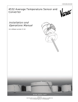
Brief operating instructions
Note!
This operating manual explains the installation and initial start-up for the level
transmitter measuring device. All functions that are required for a typical measuring
task are taken into account here.
In addition, the 7532 RTG provides many other functions that are not included in this
operating manual, such as optimizing the measuring point and converting the measured
values.
An overview of all device functions can be found on page 96.
A description of the device functions for the 7532 RTG can also be found on the
enclosed CD-ROM.
E
+
-
+
E
+
-
F
L
D
E
E
E
-
… …
… …
- flat
ceiling
- stilling
well
…
- unknown
- <1.9
- 1.9 … 4
- 4 … 10
- >10
- standard
- calm
surface
- add. agitator
…
input E
(see sketch)
input F
(see sketch)
only for
bypass +
stilling well
- ok
- too small
- too big
- unknown
- manual
displayed
(see sketch)
D and L are
confirm
or specify
range
suggestion
000
measured value
Group
selection
00
basic setup
01
safety settings
03
mounting
calibr.
09
display
04
linearisation
05
extended calibr.
06
output
0C
system
parameters
092
language
0A
diagnostics
0A0
present
error
002
tank
shape
004
process
cond.
005
empty
calibr.
006
full
calibr.
007
pipe
diameter
008
dist./
meas value
009
history
reset
051
check
distance
003
medium
property
052
range of
mapping
053
start
mapping
008
dist./
meas value
flange:
referencepoint
of measurement
- envel. curve
- incl. FAC
- incl. cust. map
- single curve
- cyclic
= 100: unlocked
100: locked≠
09A
plot settings
09B
recording
curve
0A1
previous
error
0A4
unlock
parameter
- dip table
- auto correct.
030
tank
gauging
033
dip table
mode
034/035
dip table
555 = History Reset
(333 = reset customer parameters)
0A3
reset
basic setup
dip table
offsetfirst point corrects
further points correct linearity
history reset (= 555)
Contrast: +or +

Radar Tank Gauge Table of Contents
IOM027FVAE0804 3
Table of Contents
1 Safety Instructions ....................................4
1.1 Designated use . . . . . . . . . . . . . . . . . . . . . . . . 4
1.2 Installation, commissioning and operation . . . . 4
1.3 Operational safety . . . . . . . . . . . . . . . . . . . . . . 4
1.4 Return . . . . . . . . . . . . . . . . . . . . . . . . . . . . . . . 5
1.5 Notes on safety conventions and symbols . . . . 6
2 Identification ................................................7
2.1 Device designation . . . . . . . . . . . . . . . . . . . . . . 7
2.2 Scope of delivery . . . . . . . . . . . . . . . . . . . . . . 10
2.3 Certificates and approvals . . . . . . . . . . . . . . . 10
2.4 Registered trademarks . . . . . . . . . . . . . . . . . . 10
3 Mounting ..................................................... 11
3.1 Quick installation guide . . . . . . . . . . . . . . . . . 11
3.2 Incoming acceptance, transport, storage . . . . 12
3.3 Installation Conditions . . . . . . . . . . . . . . . . . . 13
3.4 Installation instructions . . . . . . . . . . . . . . . . . . 17
3.5 Post-installation check . . . . . . . . . . . . . . . . . . 24
4 Wiring ............................................................25
4.1 Quick wiring guide . . . . . . . . . . . . . . . . . . . . . 25
4.2 Connecting the measuring unit . . . . . . . . . . . 28
4.3 Equipotential bonding . . . . . . . . . . . . . . . . . . 30
4.4 Degree of protection . . . . . . . . . . . . . . . . . . . 30
4.5 Overvoltage protector . . . . . . . . . . . . . . . . . . 30
4.6 Post-connection check . . . . . . . . . . . . . . . . . . 30
5 Operation .....................................................31
5.1 Quick operation guide . . . . . . . . . . . . . . . . . . 31
5.2 Display and operating elements . . . . . . . . . . . 34
5.3 Local operation . . . . . . . . . . . . . . . . . . . . . . . 37
5.4 Display and acknowledging error messages . 40
5.5 HART communication . . . . . . . . . . . . . . . . . . 41
6 Commissioning .........................................45
6.1 Function check . . . . . . . . . . . . . . . . . . . . . . . . 45
6.2 Commissioning . . . . . . . . . . . . . . . . . . . . . . . . 45
6.3 Basic Setup . . . . . . . . . . . . . . . . . . . . . . . . . . . 46
6.4 Basic Setup with the VU 331 . . . . . . . . . . . . . 49
6.5 Mounting calibration with VU 331 . . . . . . . . . . 57
6.6 Basic Setup with the ToF Tool . . . . . . . . . . . . . 66
6.7 Mounting calibration with the ToF Tool . . . . . . 70
7 Maintenance ...............................................73
8 Accessories ................................................75
9 Troubleshooting .......................................77
9.1 Troubleshooting instructions . . . . . . . . . . . . . . 77
9.2 System error messages . . . . . . . . . . . . . . . . . 79
9.3 Application errors . . . . . . . . . . . . . . . . . . . . . . 81
9.4 Spare parts . . . . . . . . . . . . . . . . . . . . . . . . . . . 83
9.5 Return . . . . . . . . . . . . . . . . . . . . . . . . . . . . . . . 86
9.6 Disposal . . . . . . . . . . . . . . . . . . . . . . . . . . . . . 86
9.7 Software history . . . . . . . . . . . . . . . . . . . . . . . 86
10 Technical data ...........................................87
10.1 Technical data at a glance . . . . . . . . . . . . . . . 87
11 Appendix .....................................................91
11.1 Operating menu HART (Display modul), ToF Tool
91
11.2 Operating matrix HART / Commuwin II . . . . . . 94
11.3 Description of functions . . . . . . . . . . . . . . . . . . 96
11.4 Function and system design . . . . . . . . . . . . . . 97
Index.......................................................................103

Safety Instructions Radar Tank Gauge
4 Installation and Operations Manual
1 Safety Instructions
1.1 Designated use
The Varec Model 7532 Radar Tank Gauge (RTG) is a compact radar level transmitter for
the continuous, contactless measurement of liquids, pastes and sludge in stilling wells.
The device can also be freely mounted outside closed metal vessels because of its
operating frequency of about 6 GHz and a maximum radiated pulsed energy of 1mW
(average power output 1 µW). Operation is completely harmless to humans and animals.
1.2 Installation, commissioning and operation
The 7532 RTG has been designed to operate safely in accordance with current technical,
safety and EU standards. If installed incorrectly or used for applications for which it is
not intended, however, it is possible that application-related dangers may arise, e.g.
product overflow due to incorrect installation or calibration. For this reason, the
instrument must be installed, connected, operated and maintained according to the
instructions in this manual: personnel must be authorised and suitably qualified. The
manual must have been read and understood, and the instructions followed.
Modifications and repairs to the device are permissible only when they are expressly
approved in the manual.
1.3 Operational safety
Hazardous areas
Measuring systems for use in hazardous environments are accompanied by separate “Ex
documentation”, which is an
integral part
of this Operating Manual. Strict compliance
with the installation instructions and ratings as stated in this supplementary
documentation is mandatory.
• Ensure that all personnel are suitably qualified.
• Observe the specifications in the certificate as well as national and local regulations.
FCC-approval
This device complies with part 15 of the FCC Rules. Operation is subject to the following
two conditions: (1) This device may not cause harmful interference, and (2) this device
must accept any interference received, including interference that may cause undesired
operation.
Caution!
Changes or modifications not expressly approved by the part responsible for
compliance could void the user’s authority to operate the equipment.

5
7532 Safety Instructions
1.4 Return
The following procedures must be carried out before a transmitter is sent to Varec for
repair:
• Always enclose a duly completed “Declaration of contamination” form. Only then can
Varec transport, examine and repair a returned device.
• Enclose special handling instructions if necessary, for example a safety data sheet as
per EN 91/155/EEC.
• Remove all residue which may be present. Pay special attention to the gasket grooves
and crevices where fluid may be present. This is especially important if the fluid is
dangerous to health, e.g. corrosive, poisonous, carcinogenic, radioactive, etc.
Caution!
• No instrument should be sent back for repair without all dangerous material being
completely removed first, e.g. in scratches or diffused through plastic.
• Incomplete cleaning of the instrument may result in waste disposal or cause harm to
personnel (burns, etc.). Any costs arising from this will be charged to the operator of
the instrument.

Safety Instructions Radar Tank Gauge
6 Installation and Operations Manual
1.5 Notes on safety conventions and symbols
In order to highlight safety-relevant or alternative operating procedures in the manual,
the following conventions have been used, each indicated by a corresponding symbol in
the margin.
Safety conventions
Explosion protection
Electrical symbols
Symbol Meaning
Warning!
A warning highlights actions or procedures which, if not performed correctly,
will lead to personal injury, a safety hazard or destruction of the instrument
Caution!
Caution highlights actions or procedures which, if not performed correctly,
may lead to personal injury or incorrect functioning of the instrument
Note!
A note highlights actions or procedures which, if not performed correctly, may
indirectly affect operation or may lead to an instrument response which is not
planned
0
Device certified for use in explosion hazardous area
If the 7532 RTG has this symbol embossed on its name plate it can be
installed in an explosion hazardous area
-
Explosion hazardous area
Symbol used in drawings to indicate explosion hazardous areas.
– Devices located in and wiring entering areas with the designation
“explosion hazardous areas” must conform with the stated type of
protection
.
Safe area (non-explosion hazardous area)
Symbol used in drawings to indicate, if necessary, non-explosion
hazardous areas.
– Devices located in safe areas still require a certificate if their outputs run
into explosion hazardous areas.
%
Direct voltage
A terminal to which or from which a direct current or voltage may be
applied or supplied
&
Alternating voltage
A terminal to which or from which an alternating (sine-wave) current
or voltage may be applied or supplied
)
Grounded terminal
A grounded terminal, which as far as the operator is concerned, is
already grounded by means of an earth grounding system
*
Protective grounding (earth) terminal
A terminal which must be connected to earth ground prior to making
any other connection to the equipment
+
Equipotential connection (earth bonding)
A connection made to the plant grounding system which may be of
type e.g. neutral star or equipotential line according to national or
company practice

7
7532 Identification
2 Identification
2.1 Device designation
2.1.1 Nameplate and Certification Plates
The following technical data are given on the instrument nameplate:
Figure 1: Information on the nameplate of the 7500 RTG (example)
Figure 2: Information on the NMi type plate for custody transfer applications of the
7500 RTG (example)
Figure 3: Information on the PTB type plate for custody transfer applications of the
7500 RTG (example)
7500RTG_nameplate_label.eps7500RTG_NMI_label.eps
7500RTG_ATEX-PTB_label.eps

Identification Radar Tank Gauge
8 Installation and Operations Manual
2.1.2 Ordering structure
Ordering structure 7532 RTG
10 Certificates Basic weight
A For non-hazardous areas 6.5 kg
S FM IS - Class I, Division 1, Group A-D
U CSA IS - Class I, Division 1, Group A-D
1 ATEX II 1/2 G EEx ia IIC T6, note safety instruction (XA) for electrostatic charg-
ing!
YSpecial version
20 Antenna type Additional
weight
Type Size Material Sealing
A Planar antenna DN150 / 6" SS316L FKM inside
B Planar antenna DN150 / 6" SS316L HNBR inside
E Planar antenna DN250 / 10" SS316L FKM inside
F Planar antenna DN250 / 10" SS316L HNBR inside 2.1 kg
U Planar antenna DN200 / 8" SS316L FKM inside
V Planar antenna DN200 / 8" SS316L HNBR inside 1.1 kg
W Planar antenna DN300 / 12" SS316L HNBR inside
X Planar antenna DN300 / 12" SS316L FKM inside 2.5 kg
YSpecial version
30 Process connection
Flange Dia/Pressure Standard Material
AVJ 6"/150 lbs / RF ANSI B16.5 316/316L 11.4 kg
A3J 8"/150 lbs / RF ANSI B16.5 316/316L 19.6 kg
A5J 10"/150 lbs / RF ANSI B16.5 316/316L 28.8 kg
AWJ 6"/300 lbs / RF ANSI B16.5 316/316L 20.9 kg
AXJ 8"/300 lbs / RF ANSI B16.5 316/316L 34.3 kg
A7J 12"/150 lbs / RF ANSI B16.5 316/316L 43.2 kg
CWJ DN150 PN10 / 16 C
EN 1092,1, B1
1)
316L 10.6 kg
CXJ DN200 PN16 C
EN 1092,1, B1
1)
316L 16.5 kg
CZJ DN200 PN25 C
EN 1092,1, B1
1)
316L 22.7 kg
C1J DN150 PN25 C
EN 1092,1, B1
1)
316L 14.7 kg
C6J DN250 PN16 C
EN 1092,1, B1
1)
316L 25.6 kg
C8J DN300 PN16 C
EN 1092,1, B1
1)
316L 36.1 kg
XXJ with flange hub 316L
XVU Varec UNI-Flange 6"/
DN150/150A,
max. 14.5LBS/PN1/1K,
compatible with:
- 6" 150LBS
- DN150 PN16
- 10K 150A
304/1.4301 3.5 kg
X3U Varec UNI-Flange 8"/
DN200/200A,
max. 14.5LBS/PN1/1K,
compatible with:
- 8" 150LBS
- DN200 PN16
- 10K 200A
304/1.4301 5.2 kg
X5U Varec UNI-Flange 10"/
DN250/250A,
max. 14.5LBS/PN1/1K,
compatible with:
- 10" 150LBS
- DN250 PN16
- 10K 250A
304/1.4301 7.5 kg
X7U Varec UNI-Flange 12"/
DN300/300A,
max. 14.5LBS/PN1/1K,
compatible with:
- 12" 150LBS
- DN300 PN16
- 10K 300A
304/1.4301 10.8 kg
1) agreeable to DIN2527 Form C
YY9 Special version

9
7532 Identification
40 Output and operation
A 4…20 mA HART with VU 331, 4-line alphanumeric dis-
play
YSpecial version
50 Housing
C Aluminium T12-housing with separate connection compartment, coated, IP65
YSpecial version
60 Gland / Entry
2 M20x1.5 cable gland
4 ½ NPT cable entry
9Special version
70 Custody transfer approvals
A NMi, PTB type and test rig approval,
weights&measures approved (< 1 mm)
R Inventory Control Version,
not weights&measures approved (3 mm)
Y Special approval for custody transfer
80 Additional options
A Without additional options
YSpecial version
7532- Complete product designation

Identification Radar Tank Gauge
10 Installation and Operations Manual
2.2 Scope of delivery
Caution!
It is essential to follow the instructions concerning the unpacking, transport and storage
of measuring instruments given in the section “Incoming acceptance, transport, storage”
on page 12.
The scope of delivery consists of:
• Assembled instrument
• ToF Tool (operating program)
• Accessories (Chapter 8)
Accompanying documentation:
• Short manual (basic equalization/troubleshooting): housed in the instrument
• Operating manual (this manual)
• Operating manual: Description of the instrument functions
• Approval documentation: if this is not included in the operating manual.
2.3 Certificates and approvals
CE mark, declaration of conformity
The instrument is designed to meet state-of-the-art safety requirements, has been
tested and left the factory in a condition in which it is safe to operate. The instrument
complies with the applicable standards and regulations in accordance with EN 61010
“Protection Measures for Electrical Equipment for Measurement, Control, Regulation and
Laboratory Procedures”. The instrument described in this manual thus complies with the
statutory requirements of the EG directives. Varec confirms the successful testing of the
instrument by affixing to it the CE mark.
2.4 Registered trademarks
KALREZ
®
, VITON
®
, TEFLON
®
Registered trademark of the company E.I. Du Pont de Nemours & Co., Wilmington, USA
TRI-CLAMP
®
Registered trademark of the company Ladish & Co., Inc., Kenosha, USA
HART
®
Registered trademark of HART Communication Foundation, Austin, USA
ToF
®
Registered trademark of the company Endress+Hauser GmbH+Co. KG, Maulburg, Ger-
many
PulseMaster
®
Registered trademark of the company Endress+Hauser GmbH+Co. KG, Maulburg, Ger-
many
PhaseMaster
®
Registered trademark of the company Endress+Hauser GmbH+Co. KG, Maulburg, Ger-
many

11
7532 Mounting
3 Mounting
3.1 Quick installation guide
Note!
The 7532 RTG with planar antenna is designed for use on stilling-wells only!
3
1
2
90˚
.
.
T12 housing
Turn housing
Installation only in stilling well:
The performance of the 7532 RTG
planar antenna is not dependent on the
alignment or geometry of standard stilling
wells.
No special alignment is required.
However, make sure that the planar
antenna is installed vertically relative
to the stilling well axis.
The housing can be turned
in order to simplify access to the
display and the terminal compartment
Allen key
4 mm
tighten strongly
by hand
L00-FMR532xx-17-00-00-en-002

Mounting Radar Tank Gauge
12 Installation and Operations Manual
3.2 Incoming acceptance, transport, storage
3.2.1 Incoming acceptance
Check the packing and contents for any signs of damage.
Check the shipment, make sure nothing is missing and that the scope of supply matches
your order.
3.2.2 Transport
Caution!
Follow the safety instructions and transport conditions for instruments of more than
18 kg. Do not lift the measuring instrument by its housing in order to transport it.
3.2.3 Storage
Pack the measuring instrument so that is protected against impacts for storage and
transport. The original packing material provides the optimum protection for this.
The permissible storage temperature is -40 °C…+80 °C.

13
7532 Mounting
3.3 Installation Conditions
3.3.1 Dimensions
Figure 4: Dimensions 7532 RTG
Note!
The inactive length of 60 mm prevents condensation effects to the antenna perfor-
mance. Special versions with longer construction are available.
Antenna version DN150 / 6" DN200 / 8" DN250 / 10" DN300 / 12"
L [mm] 93 337 490 517
Ø D [mm] no horn 190 240 290
ENDRESS+HAUSER
Micropilot II
65 (2.56")
Ø 129 (5.08")
Ø 150 (5.91")
Ø D
68 (2.68") 94 (3.7")
30
(1.18")
L
238 (9.37")
93 (3.66")
60
(2.36")
8 (0.31")
85 (3.35")
DIN, ANSI,
JIS
9
(0.35")
Ø 62,5 (2.46")
Ø 78 (3.07")
Ø 99,5 (3.92")
DN200…300 / 8…12”
version with
antenna widening
E+H UNI flange
(max. 1 bar)
flange hub
mounting:
4 bolts M6 / 90°
e.g.DIN 912
O-Ring 85.3 x 3.53,
included
(same material as
sensor seal)
DN150 / 6”
version without widening
detail A:
flange adapter
(see under)
detail A
flange hub for the connection
to flanges provided by the customer
inactive length
L00-FMR532xx-06-00-00-en-001

Mounting Radar Tank Gauge
14 Installation and Operations Manual
3.3.2 Engineering tips
Measuring conditions
• The measuring range starts at the bottom end of the stilling well.
• In case of media with a low dielectric constant (groups A and B), the pipe end can be
visible through the medium at low levels. In order to guarantee the required accuracy
in these cases, it is recommended to position the zero-point at a distance C above the
tank bottom (see Fig.).
• In applications with planar or parabolic antennas, especially for media with low
dielectric constants (see page 15), the end of the measuring range should not be closer
than 1 m (40”) to the flange.
•For overspill protection, it is possible to define a safety distance (SD) additionally to
the blocking distance (BD).
• This safety distance (SD) is set to 0.5 m (20") by default and generating an alarm in
case the level rises inside the safety distance.
• Distance B defined the smallest recommended measurement range.
• Depending on its consistence, foam can either absorb microwaves or reflect them off
the foam surface. Measurement is possible under certain conditions.
Behaviour if measuring range is exceeded
The behaviour in case of the measuring range being exceeded can be freely set: the
default setting is a current of 22 mA and the generation of a digital warning (E681).
reference: flange / BD
(see picture)
reference: antenna tip
(see picture)
recommended additional settings
Blocking
distance
Safety
distance
BD [m / ft] SD [m / ft] A [mm / inch] B [m / ft] C [mm / inch]
7532 RTG (planar) 1 / 3.28 0.5 / 1.6 1000 / 40 0.5 / 1.64
150…300 /
6…12
L00-FMR53xxx-17-00-00-en-008
BD
SD
A
100%
0%
B
C
max. level

15
7532 Mounting
Measuring range
The usable measuring range depends on the size of the antenna, the reflectivity of the
medium, the mounting location, and eventual interference reflections.
The following tables describe the groups of media as well as the achievable measuring
range as a function of application and media group. If the dielectric constant of a
medium is unknown, it is recommended to assume media group B to ensure a reliable
measurement.
1)Treat Ammonia NH3 as a medium of group A, e.g. always use a stilling well.
Measuring range depending on product class for 7532 RTG:
Product class DK (εr) Examples
A 1.4 … 1.9 non-conducting liquids, e.g. liquefied gas
1)
B 1.9 … 4 non-conducting liquids, e.g. benzene, oil, toluene, …
C 4 … 10 e.g. concentrated acids, organic solvents, esters, aniline,
alcohol, acetone, …
D > 10 conducting liquids, e.g. aqueous solutions, dilute acids and
alkalis
Product class Stilling well/ Bypass
Measuring range
7532 RTG
>
DN150
A DK(
εr)=1,4…1,9 38 m/124 ft
B DK(
εr)=1,9…4 38 m/124 ft
C DK(
εr)=4…10 38 m/124 ft
D DK(
εr)>10 38 m/124 ft
max. measuring
range with custody
transfer approvals
20 m/65 ft

Mounting Radar Tank Gauge
16 Installation and Operations Manual
Blocking distance
The blocking distance (= BD) is the minimum distance from the reference point of the
measurement (mounting flange) to the medium surface at maximum level.
Note!
Inside the blocking distance a reliable measurement can not be guaranteed.
Blocking distance
(BD)
Stilling well / Bypass
7532 RTG
from Flange 1 m/40"
20mA
100%
BD
referencepointof
measurement
Max.
Level
L00-FMR53xxx-15-00-00-en-003

17
7532 Mounting
3.4 Installation instructions
3.4.1 Mounting kit
In addition to the tool needed for flange mounting, you will require the following tool:
• 4 mm Allen wrench for turning the housing.
3.4.2 Installation in stilling well
Optimum mounting position for 7532 RTG
Recommendations for the stilling well
• Metal (no enamel coating, plastic on request).
•Constant diameter.
• Weld seam as smooth as possible and on the same axis as the slots.
• Slots offset 180° (not 90°).
• Slot width respectively diameter of holes max. 1/10 of pipe diameter, de-burred.
Length and number do not have any influence on the measurement.
• Select antenna extension as big as possible. For intermediate sizes (e.g. 180 mm)
select next larger antenna extension and adapt it mechanically. Maximum gap allowed
between the antenna/horn of 7532 RTG and the inside of the stilling well is 5 mm (3/
16").
• The antennna extension of the 7532 RTG is mounted with defined pressure.
It is strongly recommended not to dismantle this antenna.
• Dimensions of a nozzle for manual gauging must be adapted to the dimensions of
the horn antenna used, compare to page page 23.
Stilling wells with pipe expansion
• When using a 7532 RTG, a gradual pipe expansion from DN150 to DN200 / DN200
to DN250 / DN250 to DN300 is acceptable. In such cases, the top end of the piping
must have a minimum length of 0.5 m in front of the expansion (see table on page 18).
Ideally, a dip socket is used for this.
• Greater expansion of the piping (e.g. DN150 to DN300) is possible if the top end of
the pipe is extended accordingly (see table on page 18).
• Avoid pipe expansions at right angles.
Standard installation
When mounting in the stilling well, please
observe engineering tips on page 14 and
the following points:
• After mounting, the housing can be
turned 350° in order to simplify access to
the display and the terminal
compartment.
• planar axis vertical to flange.
• Measurements can be performed
through an open ball valve without any
problems.
L00-FMR532xx-17-00-00-en-003

Mounting Radar Tank Gauge
18 Installation and Operations Manual
Examples for the construction of stilling wells
7532 RTG
7532 RTG
L00-FMR532xx-17-00-00-en-004

19
7532 Mounting
3.4.3 Turn housing
After mounting, the housing can be turned 350° in order to simplify access to the display
and the terminal compartment. Proceed as follows to turn the housing to the required
position:
• Undo the fixing screws (1)
• Turn the housing (2) in the required direction
• Tighten up the fixing screws (1)
1
2
T12 housing
Allen key
4 mm
tighten strongly
by hand
L00-FMR532xx-17-00-00-en-005

Mounting Radar Tank Gauge
20 Installation and Operations Manual
3.4.4 Installation with Varec UNI flange
Installation tips
Varec UNI flanges are designed for non-pressurized operation respectively max. 1 bar
absolute pressure. The number of bolts has sometimes been reduced. The bolt-holes
have been enlarged for adaption of dimensions, therefore, the flange needs to be
properly aligned to the counterflange before the bolts are tightened.
Version Compatible with D [mm] K [mm] Type plate no.
1000 DN150 PN16
ANSI 6" 150lbs
JIS 10K 150
280 240 942455-3001
2000 DN200 PN16
ANSI 8" 150lbs
JIS 10K 200
340 294.5 942455-3002
3000 DN250 PN16
ANSI 10" 150lbs
JIS 10K 250
405 358 942455-3003
4000 DN300 PN16
ANSI 12" 150lbs
JIS 10K 300
482 410 (for DIN), 431,8
(for ANSI), 400 (for
JIS),
404,5 (for DIN + JIS)
942455-3004
L00-FMR53xxx-06-00-00-en-001
/