Page is loading ...

IOM001GVAE1117
Automation Solutions for oil & gas, defense and aviation applications
Installation and Operations Manual
Dispatch and Fuels Accounting
2500 Automatic Tank Gauge
Mechanically operated, float and tape gauges
for continuous liquid-level measurement in
bulk storage tanks


Varec, Inc. iii
Copyright
© 2016 All rights reserved. Printed in the United States of America.
Except as permitted under the United States Copyright Act of 1976, no part of this publication
may be reproduced, stored in a retrieval system or transmitted in any form or by any means -
electronic, mechanical, photocopying, recording, or otherwise - without the prior written
permission of the Publisher:
Varec, Inc.
5834 Peachtree Corners East
Peachtree Corners (Atlanta), Georgia 30092
Phone: (770) 447-9202
Fax: (770) 662-8939
Trademarks Acknowledged
Varec, Inc. recognizes all other trademarks. Trademarks of other products mentioned in this
manual are held by the companies producing them.
FuelsManager®, TankView®, TacFuels®, Varec®, and FuelsManager IntoPlane® are
registered trademarks of Varec, Inc.
Delrin is a registered trademark of E. I. du Pont de Nemours Co. (Inc.), Wilmington, DL
Dow Corning RTV 737 is a registered trademark of Dow Corning Inc., Midland MI
Loctite is a registered trademark of Loctite Corp., Newington, CT
Teflon is a registered trademark of E. I. du Pont de Nemours Co. (Inc.), Wilmington, DL
Viton is a registered trademark of E. I. du Pont de Nemours Co. (Inc.), Wilmington, DL
All other product and service names mentioned are the trademarks of their respective
companies.
Document Control
This document and the information provided within are controlled by the approvals agency(s)
listed below. All changes to this document must be submitted to and approved by the agency(s)
before public release.
ATEX Notified Body (FM Approvals)

Disclaimer of Warranties
The contract between the Seller and the Buyer states the entire obligation of the Seller. The
contents of this instruction manual shall not become part of or modify any prior or existing
agreement, commitment, or relationship between the Seller and Buyer. There are no express or
implied warranties set out in this instruction manual. The only warranties that apply are those
in the existing contract between the Seller and Buyer.
The 2500 Automatic Tank Gauge (ATG) has not been tested by Varec under all possible
operational conditions, and Varec may not have all the data relative to your application. The
information in this instruction manual is not all inclusive and does not and cannot take into
account all unique situations. Consequently, the user should review this product literature in
view of his or her application. If you have any further questions, please contact Varec for
assistance.
Limitations of Seller's Liability
In the event that a court holds that this instruction manual created some new warranties, Seller's
liability shall be limited to repair or replacement under the standard warranty clause. In no case
shall the Seller's liability exceed that stated as Limitations of Remedy in the contract between
the Seller and Buyer.
Use of parts that are not manufactured or supplied by Varec voids any warranty and relieves
Varec of any obligation to service the product under warranty. Varec recommends the use of
only Varec manufactured or supplied parts to maintain or service Varec 2500 Automatic Tank
Gauges.
Terms of Use
The information provided in this document is provided "as is" without warranty of any kind.
Varec, Inc. disclaim all warranties, either express or implied, including the warranties of
merchantability and fitness for a particular purpose. In no event shall Varec, Inc. or its suppliers
be liable for any damages whatsoever including direct, indirect, incidental, consequential, loss
of business profits or special damages, even if Varec, Inc. or its suppliers have been advised of
the possibility of such damages.
This manual is solely intended to describe product installation and functions and should not be
used for any other purpose. It is subject to change without prior notice. This manual was
prepared with the highest degree of care. However, should you find any errors or have any
questions, contact one of our service offices or your local sales agent.
iv Installation and Operations Manual

Safety Precaution Definitions
Caution! Damage to equipment may result if this precaution is disregarded.
Warning! Direct injury to personnel or damage to equipment which can cause injury to
personnel may result if this precaution is not followed.
Safety Precautions
Read this manual carefully and make sure you understand its contents before using this product.
Follow all instructions and safety guidelines presented in this manual when using this product.
If the user does not follow these instructions properly, Varec cannot guarantee the safety of the
system.
Note Comply with all applicable regulations, codes, and standards. For safety precautions,
the user should refer to the appropriate industry or military standards.
Caution! Electrical Hazard! Read and understand static and lightning electrical protection
and grounding described in API 2003. Make certain that the tank installation, operation,
and maintenance conforms with the practice set forth therein.
Warning! Striking the gauge head with a metal object could cause a spark to occur. When
removing or replacing the gauge head in flammable or hazardous liquid storage areas, take
necessary measures to protect the gauge head from impact.
Warning! Volatile fumes may be present! Make certain that the tank is empty and not in
service. Ensure that the tank has been leak and pressure tested as appropriate for the liquid
to be stored. Observe appropriate safety precautions in flammable or hazardous liquid
storage areas. Do not enter a tank that has contained hydrocarbons, vapors, or toxic
materials, until a gas-free environment is certified. Carry breathing equipment when
entering a tank where oxygen may be displaced by carbon dioxide, nitrogen, or other gases.
Wear safety glasses as appropriate. Use a hard hat.
Warning! Sparks or static charge could cause fire or explosion! The mechanical
connections between the guide cables, the float, the tape, and the gaugehead provide a
resistance to ground that is adequate for the safe electrical drain of electrostatic charges
that may accumulate in the tank and the product. Worker activity and worker clothing may
accumulate electrostatic charges on the body of a worker. Care should be used in
flammable environments to avoid the hazard.
Warning! Broken negator motor spring pieces can cause injury when the back cover of the
gauge head is removed! Whenever the back cover is removed, stand to one side as the last
bolt is removed.
Varec, Inc. v

vi Installation and Operations Manual

Varec, Inc. 7
Contents
1 Introduction . . . . . . . . . . . . . . . . . . . . . . . . . . . . . . . . . . . . . . . . . . . . . . . . 1
Using this Manual . . . . . . . . . . . . . . . . . . . . . . . . . . . . . . . . . . . . . . . . . . . . . . . . . . . . . . . . . . .1
Getting Acquainted with the 2500 Automatic Tank Gauge Systems . . . . . . . . . . . . . . . . . . . .2
Tank Gauge Operation . . . . . . . . . . . . . . . . . . . . . . . . . . . . . . . . . . . . . . . . . . . . . . . . .3
Calibration and Volume Measurement . . . . . . . . . . . . . . . . . . . . . . . . . . . . . . . . . . . . .3
System Integration . . . . . . . . . . . . . . . . . . . . . . . . . . . . . . . . . . . . . . . . . . . . . . . . . . . .4
Product Options . . . . . . . . . . . . . . . . . . . . . . . . . . . . . . . . . . . . . . . . . . . . . . . . . . . . . . . . . . . .4
English and Metric Configurations . . . . . . . . . . . . . . . . . . . . . . . . . . . . . . . . . . . . . . . . .4
Check Knob . . . . . . . . . . . . . . . . . . . . . . . . . . . . . . . . . . . . . . . . . . . . . . . . . . . . . . . . . .5
Negator Cassette . . . . . . . . . . . . . . . . . . . . . . . . . . . . . . . . . . . . . . . . . . . . . . . . . . . . .5
Float Crank . . . . . . . . . . . . . . . . . . . . . . . . . . . . . . . . . . . . . . . . . . . . . . . . . . . . . . . . . .5
2 General Preparation . . . . . . . . . . . . . . . . . . . . . . . . . . . . . . . . . . . . . . . . . . 7
Safety Precautions . . . . . . . . . . . . . . . . . . . . . . . . . . . . . . . . . . . . . . . . . . . . . . . . . . . . . . . . . .7
Tools, Equipment, and Materials . . . . . . . . . . . . . . . . . . . . . . . . . . . . . . . . . . . . . . . . . . . . . . .7
Guidelines, Recommendations, and Options When Preparing for Installation . . . . . . . . . . . . .8
Floating Roof Tank Installations . . . . . . . . . . . . . . . . . . . . . . . . . . . . . . . . . . . . . . . . . .8
Guide Wires and Anchors . . . . . . . . . . . . . . . . . . . . . . . . . . . . . . . . . . . . . . . . . . . . . . .8
Support Brackets . . . . . . . . . . . . . . . . . . . . . . . . . . . . . . . . . . . . . . . . . . . . . . . . . . . . . .9
Conduit (Pipework) and Couplings . . . . . . . . . . . . . . . . . . . . . . . . . . . . . . . . . . . . . . . .9
Tank Roof Entry via Manhole & Inspection Covers . . . . . . . . . . . . . . . . . . . . . . . . . . .10
Floats . . . . . . . . . . . . . . . . . . . . . . . . . . . . . . . . . . . . . . . . . . . . . . . . . . . . . . . . . . . . . .11
Identifying Your Installation Type . . . . . . . . . . . . . . . . . . . . . . . . . . . . . . . . . . . . . . . . . . . . . .11
Cone Roof Tank . . . . . . . . . . . . . . . . . . . . . . . . . . . . . . . . . . . . . . . . . . . . . . . . . . . . .11
Bolted Tank . . . . . . . . . . . . . . . . . . . . . . . . . . . . . . . . . . . . . . . . . . . . . . . . . . . . . . . . .12
Cone Roof Tank with Internal (Floating Roof) Pan and Floatwell . . . . . . . . . . . . . . . .13
Cone Roof Tank and Internal (Floating Roof) Pan: No Floatwell . . . . . . . . . . . . . . . .14
Tank Top Mounting . . . . . . . . . . . . . . . . . . . . . . . . . . . . . . . . . . . . . . . . . . . . . . . . . . .15
Stilling Well Service Cone Roof Tank 6" Diameter Float . . . . . . . . . . . . . . . . . . . . . . .16
External Floating Roof Tank and Floatwell . . . . . . . . . . . . . . . . . . . . . . . . . . . . . . . . .17
External Floating Roof Tank: No Floatwell . . . . . . . . . . . . . . . . . . . . . . . . . . . . . . . . .18
Interface Service . . . . . . . . . . . . . . . . . . . . . . . . . . . . . . . . . . . . . . . . . . . . . . . . . . . . .19
3 Installation . . . . . . . . . . . . . . . . . . . . . . . . . . . . . . . . . . . . . . . . . . . . . . . . 21
Installation Schematics . . . . . . . . . . . . . . . . . . . . . . . . . . . . . . . . . . . . . . . . . . . . . . . . . . . . . .21
Tank Roof Entry - Cone Roof Tank . . . . . . . . . . . . . . . . . . . . . . . . . . . . . . . . . . . . . . . . . . . .23
Tank Roof Entry - Internal Pan (Floating Roof) . . . . . . . . . . . . . . . . . . . . . . . . . . . . . . . . . . .24
Tank Roof Entry - Stilling Well . . . . . . . . . . . . . . . . . . . . . . . . . . . . . . . . . . . . . . . . . . . . . . . .25
Correct Float Positioning for an External Floating Pan Installation . . . . . . . . . . . . . . . . . . . . .25
Installing Anchors and Guide Wires . . . . . . . . . . . . . . . . . . . . . . . . . . . . . . . . . . . . . . . . . . . .25
Installing Support Brackets & Pipework . . . . . . . . . . . . . . . . . . . . . . . . . . . . . . . . . . . . . . . . .27
Installing a Gauge Head at Grade Level . . . . . . . . . . . . . . . . . . . . . . . . . . . . . . . . . . . . . . . . .28
Installing a Roof Reading Gauge Head . . . . . . . . . . . . . . . . . . . . . . . . . . . . . . . . . . . . . . . . .29
Float installation on an Out-of-Service Tank . . . . . . . . . . . . . . . . . . . . . . . . . . . . . . . . . . . . . .30
Cone Roof Tank . . . . . . . . . . . . . . . . . . . . . . . . . . . . . . . . . . . . . . . . . . . . . . . . . . . . .30
Floating Pan with Floatwell . . . . . . . . . . . . . . . . . . . . . . . . . . . . . . . . . . . . . . . . . . . . .30
Connecting the Tape to the Float . . . . . . . . . . . . . . . . . . . . . . . . . . . . . . . . . . . . . . . . . . . . . .30

2500 Automatic Tank Gauge
8 Installation and Operation Manual
Connecting the Cable to a Float in a Floatwell . . . . . . . . . . . . . . . . . . . . . . . . . . . . . . . . . . . .31
Connecting the Cable to a Floating Pan . . . . . . . . . . . . . . . . . . . . . . . . . . . . . . . . . . . . . . . . .33
Connecting the Tape to a 6" Interface Float in an 8" Stilling Well . . . . . . . . . . . . . . . . . . . . .33
Feeding the Tape to a Gauge Head Located at Grade Level . . . . . . . . . . . . . . . . . . . . . . . . .34
Install Tape in the Gauge Head . . . . . . . . . . . . . . . . . . . . . . . . . . . . . . . . . . . . . . . . . . . . . . .35
With a Negator Spring Motor . . . . . . . . . . . . . . . . . . . . . . . . . . . . . . . . . . . . . . . . . . . .36
With a Negator Cassette . . . . . . . . . . . . . . . . . . . . . . . . . . . . . . . . . . . . . . . . . . . . . . .37
With a Hand Crank Gauge Head . . . . . . . . . . . . . . . . . . . . . . . . . . . . . . . . . . . . . . . . .38
Trimming the Cable at the Float in a Floatwell . . . . . . . . . . . . . . . . . . . . . . . . . . . . . . . . . . . .39
Reset the Counter . . . . . . . . . . . . . . . . . . . . . . . . . . . . . . . . . . . . . . . . . . . . . . . . . . . . . . . . . .40
Calibrate the Counter . . . . . . . . . . . . . . . . . . . . . . . . . . . . . . . . . . . . . . . . . . . . . . . . . . . . . . .41
Initial Lubrication . . . . . . . . . . . . . . . . . . . . . . . . . . . . . . . . . . . . . . . . . . . . . . . . . . . . . . . . . . .42
Install a Transmitter and Replace all Covers . . . . . . . . . . . . . . . . . . . . . . . . . . . . . . . . . . . . .42
Initial Operation . . . . . . . . . . . . . . . . . . . . . . . . . . . . . . . . . . . . . . . . . . . . . . . . . . . . . . . . . . . .43
4 In-Service Installation Procedures . . . . . . . . . . . . . . . . . . . . . . . . . . . . . 45
Negator Cassette Installation . . . . . . . . . . . . . . . . . . . . . . . . . . . . . . . . . . . . . . . . . . . . . . . . .46
Disassembly . . . . . . . . . . . . . . . . . . . . . . . . . . . . . . . . . . . . . . . . . . . . . . . . . . . . . . . .46
Assembly . . . . . . . . . . . . . . . . . . . . . . . . . . . . . . . . . . . . . . . . . . . . . . . . . . . . . . . . . . .47
Oil Seal Installation . . . . . . . . . . . . . . . . . . . . . . . . . . . . . . . . . . . . . . . . . . . . . . . . . . . . . . . . .49
27-inch Water column operating pressure oil seal . . . . . . . . . . . . . . . . . . . . . . . . . . .50
8.5-inch Water column operating pressure oil seal . . . . . . . . . . . . . . . . . . . . . . . . . . .51
Inspection Hatch and Manhole Cover . . . . . . . . . . . . . . . . . . . . . . . . . . . . . . . . . . . . . . . . . . .52
Inspection Hatch . . . . . . . . . . . . . . . . . . . . . . . . . . . . . . . . . . . . . . . . . . . . . . . . . . . . .52
Manhole Cover . . . . . . . . . . . . . . . . . . . . . . . . . . . . . . . . . . . . . . . . . . . . . . . . . . . . . .52
Guide Wire Bottom Anchors . . . . . . . . . . . . . . . . . . . . . . . . . . . . . . . . . . . . . . . . . . . . . . . . . .53
In-service Float & Guide Wire Installation . . . . . . . . . . . . . . . . . . . . . . . . . . . . . . . . . . . . . . . .53
5 Operation . . . . . . . . . . . . . . . . . . . . . . . . . . . . . . . . . . . . . . . . . . . . . . . . . 57
6 Gauge Head Disassembly and Re-assembly . . . . . . . . . . . . . . . . . . . . . 59
Gauge Head Disassembly . . . . . . . . . . . . . . . . . . . . . . . . . . . . . . . . . . . . . . . . . . . . . . . . . . .59
Gauge Head Assembly . . . . . . . . . . . . . . . . . . . . . . . . . . . . . . . . . . . . . . . . . . . . . . . . . . . . . .64
Counter Wheel Assembly . . . . . . . . . . . . . . . . . . . . . . . . . . . . . . . . . . . . . . . . . . . . . . . . . . . .66
Counter Bearing Adjustment Procedure . . . . . . . . . . . . . . . . . . . . . . . . . . . . . . . . . . . . . . . . .67
7 Maintenance Routines . . . . . . . . . . . . . . . . . . . . . . . . . . . . . . . . . . . . . . . 69
Operation Check . . . . . . . . . . . . . . . . . . . . . . . . . . . . . . . . . . . . . . . . . . . . . . . . . . . . . . . . . . .70
Leak Check . . . . . . . . . . . . . . . . . . . . . . . . . . . . . . . . . . . . . . . . . . . . . . . . . . . . . . . . . . . . . . .70
Sediment Check . . . . . . . . . . . . . . . . . . . . . . . . . . . . . . . . . . . . . . . . . . . . . . . . . . . . . . . . . . .70
Deformation Check . . . . . . . . . . . . . . . . . . . . . . . . . . . . . . . . . . . . . . . . . . . . . . . . . . . . . . . . .70
Calibration Check . . . . . . . . . . . . . . . . . . . . . . . . . . . . . . . . . . . . . . . . . . . . . . . . . . . . . . . . . .70
Float and Guide Wires Check . . . . . . . . . . . . . . . . . . . . . . . . . . . . . . . . . . . . . . . . . . . . . . . . .70
Lubrication . . . . . . . . . . . . . . . . . . . . . . . . . . . . . . . . . . . . . . . . . . . . . . . . . . . . . . . . . . . . . . .71
Other Lubricants Recommended for General Service . . . . . . . . . . . . . . . . . . . . . . . .71
Other Lubricants for Service below 25°F (-4°C) . . . . . . . . . . . . . . . . . . . . . . . . . . . . .71
Oil-Filled Gauge Check . . . . . . . . . . . . . . . . . . . . . . . . . . . . . . . . . . . . . . . . . . . . . . . . . . . . . .71
Corrosion Check . . . . . . . . . . . . . . . . . . . . . . . . . . . . . . . . . . . . . . . . . . . . . . . . . . . . . . . . . . .72
Basic Maintenance . . . . . . . . . . . . . . . . . . . . . . . . . . . . . . . . . . . . . . . . . . . . . . . . . . . . . . . . .72
Extended Maintenance . . . . . . . . . . . . . . . . . . . . . . . . . . . . . . . . . . . . . . . . . . . . . . . . . . . . . .72
Overhaul / Maintenance . . . . . . . . . . . . . . . . . . . . . . . . . . . . . . . . . . . . . . . . . . . . . . . . . . . . .72

Contents
Varec, Inc. 9
General Inspection . . . . . . . . . . . . . . . . . . . . . . . . . . . . . . . . . . . . . . . . . . . . . . . . . . . . . . . . .72
8 Spare Parts and Maintenance Kits . . . . . . . . . . . . . . . . . . . . . . . . . . . . . 73
Gauge Head Spare Parts . . . . . . . . . . . . . . . . . . . . . . . . . . . . . . . . . . . . . . . . . . . . . . . . . . . .73
2500 Cast Iron Gaugehead Spare Parts . . . . . . . . . . . . . . . . . . . . . . . . . . . . . . . . . . . . . . . .81
Basic Maintenance Kit . . . . . . . . . . . . . . . . . . . . . . . . . . . . . . . . . . . . . . . . . . . . . . . . . . . . . .84
Extended Maintenance Kit . . . . . . . . . . . . . . . . . . . . . . . . . . . . . . . . . . . . . . . . . . . . . . . . . . .85
Additional items . . . . . . . . . . . . . . . . . . . . . . . . . . . . . . . . . . . . . . . . . . . . . . . . . . . . . .87
Overhaul/Refurbishing Kit . . . . . . . . . . . . . . . . . . . . . . . . . . . . . . . . . . . . . . . . . . . . . . . . . . . .88
Additional items . . . . . . . . . . . . . . . . . . . . . . . . . . . . . . . . . . . . . . . . . . . . . . . . . . . . . .92
Shoulder Bushing Retrofit Kit . . . . . . . . . . . . . . . . . . . . . . . . . . . . . . . . . . . . . . . . . . . . . . . . .92
Negator Cassette and Negator Cassette Kit . . . . . . . . . . . . . . . . . . . . . . . . . . . . . . . . . . . . . .93
Float Grounding Kit . . . . . . . . . . . . . . . . . . . . . . . . . . . . . . . . . . . . . . . . . . . . . . . . . . . . . . . . .95
Other Accessories . . . . . . . . . . . . . . . . . . . . . . . . . . . . . . . . . . . . . . . . . . . . . . . . . . . . . . . . .95
Gauge Calibrator Assembly . . . . . . . . . . . . . . . . . . . . . . . . . . . . . . . . . . . . . . . . . . . .95
Condensate Reservoir . . . . . . . . . . . . . . . . . . . . . . . . . . . . . . . . . . . . . . . . . . . . . . . . .96
Shock Absorber . . . . . . . . . . . . . . . . . . . . . . . . . . . . . . . . . . . . . . . . . . . . . . . . . . . . . .96
Floating Roof Anchor Weight . . . . . . . . . . . . . . . . . . . . . . . . . . . . . . . . . . . . . . . . . . .96
Part Numbers for Complete Gauge Heads Spare Parts . . . . . . . . . . . . . . . . . . . . . . . . . . . . .96
9 Troubleshooting . . . . . . . . . . . . . . . . . . . . . . . . . . . . . . . . . . . . . . . . . . . . 99
Dials Do Not Respond When Gauge Check Knob is Rotated . . . . . . . . . . . . . . . . . . . . . . . .99
Calibration Repeatability Unstable . . . . . . . . . . . . . . . . . . . . . . . . . . . . . . . . . . . . . . . . . . . .100
10 Specifications and Reference Data . . . . . . . . . . . . . . . . . . . . . . . . . . . 103
Device Designation/Nameplate . . . . . . . . . . . . . . . . . . . . . . . . . . . . . . . . . . . . . . . . . . . . . .103
CE Marks, Declaration of Conformity . . . . . . . . . . . . . . . . . . . . . . . . . . . . . . . . . . . . . . . . . .103
2500 ATG Gauge Head . . . . . . . . . . . . . . . . . . . . . . . . . . . . . . . . . . . . . . . . . . . . . . . . . . . .103
2500 ATG Product Dimensions . . . . . . . . . . . . . . . . . . . . . . . . . . . . . . . . . . . . . . . . . . . . . .104
Floats . . . . . . . . . . . . . . . . . . . . . . . . . . . . . . . . . . . . . . . . . . . . . . . . . . . . . . . . . . . . . . . . . .105
Conduit Elbows . . . . . . . . . . . . . . . . . . . . . . . . . . . . . . . . . . . . . . . . . . . . . . . . . . . . . . . . . . .105
Standard Installation Kits . . . . . . . . . . . . . . . . . . . . . . . . . . . . . . . . . . . . . . . . . . . . . . . . . . .106
Oil Seals . . . . . . . . . . . . . . . . . . . . . . . . . . . . . . . . . . . . . . . . . . . . . . . . . . . . . . . . . . . . . . . .106
Approvals . . . . . . . . . . . . . . . . . . . . . . . . . . . . . . . . . . . . . . . . . . . . . . . . . . . . . . . . . . . . . . .107
Other Specifications . . . . . . . . . . . . . . . . . . . . . . . . . . . . . . . . . . . . . . . . . . . . . . . . . . . . . . .107
11 Order Codes . . . . . . . . . . . . . . . . . . . . . . . . . . . . . . . . . . . . . . . . . . . . . . 109
Aluminum Gauge Head – English Configuration – Negator Motor . . . . . . . . . . . . . . . . . . . .109
Aluminum Gauge Head – Metric Configuration – Negator Motor . . . . . . . . . . . . . . . . . . . . .110
Aluminum Gauge Head – English Configuration – Float Crank . . . . . . . . . . . . . . . . . . . . . .110
Aluminum Gauge Head – Metric Configuration – Float Crank . . . . . . . . . . . . . . . . . . . . . . .110
Iron Gauge Head – English Configuration . . . . . . . . . . . . . . . . . . . . . . . . . . . . . . . . . . . . . .111
Iron Gauge Head – Metric Configuration . . . . . . . . . . . . . . . . . . . . . . . . . . . . . . . . . . . . . . .111
Aluminum Gauge Head – English Configuration – Negator Cassette . . . . . . . . . . . . . . . . .111
Aluminum Gauge Head – Metric Configuration – Negator Cassette . . . . . . . . . . . . . . . . . .112

2500 Automatic Tank Gauge
10 Installation and Operation Manual

Varec, Inc. 1
Chapter 1
Introduction
Using this Manual
This manual is designed to assist the user in the installation, operation, maintenance, and
troubleshooting of low-pressure 2500 Automatic Tank Gauges. Former 2600 Series gauges
with a hand crank are included. These gauges are for use at atmospheric pressure or at low
pressure (2.5 psig). Medium- and high-pressure tanks are served by the 2520 ATG gauges for
pressure vessels to 300 psig and are covered in their respective product manuals.
Proper operation of the gauge requires the user to pay serious attention to assuring high
quality control during the installation. Long term, satisfactory performance of the gauge can
thus be obtained. If the installation quality is compromised, gauge accuracy, and life may be
degraded.

2500 Automatic Tank Gauge
2 Installation and Operations Manual
Getting Acquainted with the 2500 Automatic Tank
Gauge Systems
The 2500 series of Automatic Tank Gauges (ATG)
are float and tape operated instruments designed
to provide continuous liquid-level measurement
in bulk storage applications.
The gauge can be installed on the tank roof or at
the tank side (at grade), which would facilitate
ground level reading by the operator and is
available with a wide variety of accessories for
virtually every tank gauging application.
The level measurement is displayed using a dial
and counter built into the gauge head. If
electronic transmission of level data or
temperature measurement integration is
required in the control room, the gauge can be
fitted with an optional tank gauging transmitter.
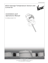
Figure 1: Typical 2500 ATG Installation
Inventory Management System
e.g. FuelsManager
Tank Gauge Interface
e.g. 8130RTU
2500 Automatic Tank Gauge
and Transmitter

Introduction
Varec, Inc. 3
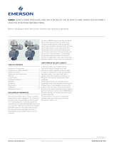
Tank Gauge Operation
The 2500 ATG uses a large, stainless steel float
attached to a stainless steel perforated tape to
detect the liquid level. The float follows the liquid
level as it rises and falls due to the tension
provided by a powerful negator spring or
cartridge motor. The precisely perforated tape
engages pins on a sprocket wheel that in turn
drive the counter assembly. This simple design
and operation allows the gauge to perform with
negligible maintenance throughout its working
life. (In some systems, the roof of the tank serves
as the float — Varec does not recommend this.)
Figure 2: 2500 ATG Powered by Negator Motor No
Electricity Required
Calibration and Volume Measurement
Tank gauging measurements provide appropriate inventory checks and a valuable method of
checking marine receipts and metered custody transfers. Accuracy of measurements requires
that a number of factors be considered:
• Density and specific gravity of product as determined from representative samples
• Sediment in the tank
• Water content in the product
• Gross volume
• Temperature of the product
• Tank-bottom deformation
It is the user's responsibility to appropriately consider these and other factors in this
application. For example, oil tank capacity tables are calculated for product at 60
o
F. A higher
temperature will cause the tank to expand, and the actual volume will be greater than the
volume at the standard temperature
Sprocket
Wheel
Mechanical
Counter
Motor
Drum
Perforated
Tape
Liquid-level Float
API Standard Description
2550
Method For Measurement And Calibration Of Upright Cylindrical Tanks
(ANSI/ASTM D1220)
2545
Method of Gauging Petroleum and Petroleum Products (ANSI/ASTM
D1085)

2500 Automatic Tank Gauge
4 Installation and Operations Manual
Table 1: Calibration and Volume Measurement
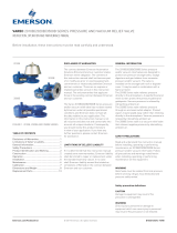
System Integration
A range of analog and digital tank gauge
transmitters is available that mounts directly to
mechanical tank gauges.
Figure 3: 2500 ATG with a 2910 Float & Tape Trans-
mitter
Level measurement data is encoded by the
transmitter and output via industry standard
communications to the control room. Some
transmitters also offer spot temperature
measurement integration that can be used for
inventory control applications. When a tank gauge transmitter is used, communications and
power are required at the gaugehead. Varec transmitters do not require an adaptor flange.
When connecting third-party equipment, a specific adaptor flange, depending on the
transmitter, is often required.
Product Options
English and Metric Configurations
Varec provides the following three measurement and display configurations:
• English fractional - feet/inches/16ths
• English decimal - feet/inches/10ths
• Metric configurations - meters/10ths/100ths
English reading gauges are manufactured with a reversible fractional/decimal dial. For
example, if the customer desires a decimal level display, the dial can be removed, reversed and
reinstalled to show decimal units. All dial/counters reflect product innage. For outage reading
requirements, Varec offers a conversion kit (Part #13-08774) for English units of measure only.
Consult Varec if metric outage is required.
2540
Chapter 11.1 (ANSI/ASTM D1250) for Volume Correction Factors. Refer
also to API 2545.
Manual of Petroleum Measurement Standards, Chapter 3 - Tank Gauging, Section 1B, Standard
Practice for Level Measurement of Liquid Hydrocarbons in Stationary Tanks by Automatic Tank
Gauging.
API Standard Description

Introduction
Varec, Inc. 5
Check Knob
An operation checker, provided as a standard feature on both the 2500 and 2520 ATG, permits
your technician to check the instrument for correct operation.
Negator Cassette
The negator cassette improves the performance of your mechanical tank gauge by self-aligning
the tape and motor as it provides the constant pullback tension required for the float to follow
the liquid level. The cassette increases reliability and reduces maintenance by protecting
internal moving parts from pipe debris that could cause stretching or corrosion. It also allows
for safer, easier, and quicker service because there is no tape to pull out or negator hubs to
unwind in your hands.
Float Crank
The float crank allows your operators to manually raise and lower the float. This can be useful
during turbulent mixing conditions so that the float or tape is not damaged.

2500 Automatic Tank Gauge
6 Installation and Operations Manual

Varec, Inc. 7
Chapter 2
General Preparation
Safety Precautions
Before installing your 2500 ATG, read and review the see the “Safety Precautions” section of
the preface to this document. Continuing with the installation according to the instructions in
this manual presumes you have reviewed these safety precautions.
The instructions to install the perforated tape in the gauge head vary depending on the type
of tape winding mechanism in your gauge head. The instructions for each of these methods
follow the basic 2500 ATG system installation instructions. They include:
• Negator Spring Motor
• Negator Cassette
• Hand Crank
This manual does not cover all possible installations. Contact Varec if you need additional
support or information for your installation.
Tools, Equipment, and Materials
User responsibilities include provision of the following items:
• 1.5-inch conduit that carries the perforated tape
• Necessary mounting and support pipe and welding
• Drilling of any holes in the tank as needed
• Assembling the necessary tools and equipment at the work site
Table 1 lists typical tools and equipment that may be needed. Use a drop cloth to maintain
tool, equipment and installation kit cleanliness.
Table 1: User-Supplied Typical Tools and Equipment
Tools, Equipment, and Materials
tape measure - long string level Pipe taps & dies
cable cutter chalk & line vice light oil
pipe cutter compass protractor Dow Corning 4 compound
sheet metal shears plumb bob Electric drill & bits Dow Corning RTV 737
hole cutters screwdrivers tank hand gauge Loctite 567
pick pliers Welding equipment Loctite 262
shovel wrenches clean drop cloth

2500 Automatic Tank Gauge
8 Installation and Operations Manual
Guidelines, Recommendations, and Options When
Preparing for Installation
Various installation options and accessories are available to suit the user installation
requirements. This section provides an overview and basic recommendations for elements of
a 2500 ATG installation.
It is paramount that the user monitor the quality of the installation to assure long-term,
accurate performance. All parts of the gauge head, tape, and float should move freely to
reduce wear and maintenance. If the quality is compromised, an inferior operation may result.
How a guide wire is anchored at the tank bottom and welding parts to or in the tank are major
considerations. These additional items are also critical to a successful installation and
operation of the 2500 ATG:
• Accurate hand gauging referenced to the tank bench mark
• Clean interior of the gauge piping
• No kinks in the tape or tape cable
• No noticeable binding friction in the mechanism
• Installation cleanliness
• True vertical gauge piping
• Location of float away from inlet pipes of mixers
Note Varec service contracts provide the user substantial savings for maintaining and
refurbishing the systems already in service.
Floating Roof Tank Installations
Warning Varec recommends that gauges be installed in a floatwell, rather than attaching
the tape directly to the tank roof.
The floatwell should contain a baffle to prevent the float from escaping while allowing
sufficient product movement to equalize the liquid level. No tape should be exposed outside
of the roof or pipework. If any section of the tape is currently exposed, it should be replaced
with a stainless steel, flexible cable. This will reduce measurement error due to wind drift. The
connector between the tape and cable should not run over a conduit elbow (or pulley).
Note An internal floating roof is often referred to as a “Pan”, e.g. a cone roof tank with a
pan and floatwell.
Varec offers a kit with a weight that sits on top of the floating roof rather than attaching
directly to the roof. This protects the tape or cable from breaking.
Warning Floating roof must be reinforced below the weight.
Guide Wires and Anchors
Note Varec recommends guide wire installations or stilling well installations where pos-
sible.

Varec, Inc. 9
Varec recommends guide wire installations for the 2500 ATG with standard guide wire centers
of 17" (432 mm) when a standard 14.5" (368 mm) diameter (Type 316 stainless steel hollow
shell) float is used. Guide Wires provide stability for the float during turbulent conditions and
provide increased accuracy by reducing the horizontal movement of the float across the
surface of the product. The guide wires should be installed centered and free of twists or kinks.
Check the movement of the float for friction or impended movement before final operation.
Varec provides two options for tank bottom, guide wire anchors, in-service and out-of-service
anchors. An anchor that can be welded to the tank bottom is used when the tank is
out-of-service (Part #AA1025). A weight can be used as an alternative when the installation is
performed while the tank is in service (Part #BA4481).
Varec top guide wire anchors can be screwed or welded into the tank roof, maintenance hatch,
or manhole cover.
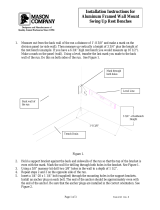
Support Brackets
“A” frame brackets support the conduit (pipework) that carries
the tape. These brackets can be welded or bolted to the tank
and should be placed at regular intervals (approx. 10ft or 3
meters) to provide uniform support. The pipework should be
held rigidly in place and correctly aligned so that the tape does
not touch or rub the internal pipework.
The steel pipe support bracket is used on the side of the tank
(Part #B5643-003). The upper support bracket assembly is
used at the tank top (Part #BM717).
Figure 1: Support brackets and conduit shown on an external
floating roof tank
Conduit (Pipework) and Couplings
Plan the pipe routing and make sure you have the required conduit, elbows, and other
materials needed. Couplings and unions can be used to easily connect sections of pipework
together without welding. They also provide a means to maintain the pipework, tape and
gauge head. Vertical runs must be plumbed to be perpendicular to prevent the tape from
binding inside the pipe.
The pipe carrying the perforated tape must be attached to the tank by welding the supplied
brackets. If the environment is such that welding cannot be performed, the user can construct
a support structure with 3-inch (76 mm) pipe or conduit close to the outside of the tank. The
brackets can be welded to the support structure at another location, if necessary, and the pipe
structure assembled at the tank site.

2500 Automatic Tank Gauge
10 Installation and Operations Manual
Conduit Elbows
Conduit elbows reduce friction and wear on the tape and provide various installation options,
depending on the tank type. Varec can provide various angles, materials, and low/high
pressure options.
Conduit Oil Seals (Optional)
Oil seals designed into the conduit pipework
during installation can help reduce wear and
maintenance on the tape, conduit, and gauge
head parts. These optional seals also prevent the
loss of damaging fumes or corrosive vapors.
Figure 2: Conduit Oil Seals
Oil seals are rated for 8.5" wc and 27" wc
respectively. Sealing fluid must have a minimum
specific gravity of 0.84 for the oil seal to maintain
integrity. Contact Varec Technical Support for
assistance if the sealing fluid does not meet this
criteria.
Tank Roof Entry via Manhole & Inspection Covers
Varec highly recommends a manhole or inspection cover be
installed for ease of installation and maintenance of the float, tape,
and guide wires. Tape conduit and guide wire anchor entries into
the tank roof should be near an existing manhole cover (within
arms reach) or be made through a manhole cover. If this is not the
case, install a manhole or inspection hatch.
A manhole cover (Model 226) allows for in-service installation of
the 2500 ATG through a tank’s existing manway. Each of the three
port entries is threaded for simple installation of pipework or guide
wire anchors. (Part #BM3443 for 20”, Part #BM3607 for 24”).
An inspection cover (Model 228) can be installed onto an existing
manhole cover, or directly on the tank roof, next to the three port
entries to provide an easily removable inspection plate
(Part # BM6746).
Figure 3: Inspection and Manhole Covers
/