DMP 867 Style W LX-BUS Notification Module Installation guide
- Category
- Fire protection
- Type
- Installation guide
This manual is also suitable for

867 STYLE W LX-BUS
NOTIFICATION MODULE
Installation Guide
DESCRIPTION
5
6
7
8
4
3
2
1
BELL
+ IN
BELL
- IN
BELL
+ OUT
BELL
- OUT
BELL
TRBL
BELL
TRBL
PS
MON
MON
ATN
BELL SILENCE
BELL NORMAL
MODEL
867
PS
TRBL
TENS ONES
TENS
SUPERVISORY ADDR
BELL ADDRESS
ONES
RING
STYL
DATA
BELL
TRBL
GND
FAULT
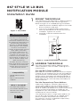
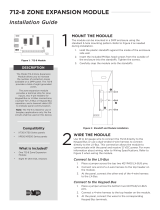
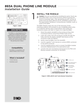
The 867module provides
one supervised Style W
notification appliance circuit
for powering polarized 12or
24VDC fire notification
devices on XR150/XR550
Series panels. The module
connects to the panel
LX‑Bus and provides ground
fault, open, and short
condition supervision on
the notification circuit. The
module has four LEDs to
indicate circuit trouble and
ground fault conditions, as
well as power supply and
data monitoring.
The 867also has a silence
switch that allows technicians
to disable the module bell
output during service and
maintenance checks.
Compatibility
• XR150/XR550Series
panels
• 505‑12 Series power
supplies
What is Included?
• One 867NAC Module
• One Model 308 10k Ohm
Resistor with Leads
• Hardware Pack
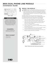
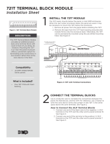
MOUNT THE MODULE
Themodule can be mounted in a DMP enclosure
using the standard3‑hole mounting pattern.
Refer to Figure 2 as needed during installation.
1. Hold the plastic standos against the inside
of the enclosure side wall.
2. Insert the included Phillips head screws
from the outside of the enclosure into the
standos. Tighten the screws.
3. Carefully snap the module onto the
standos.
ADDRESS THE MODULE
For more information about addressing and
switch locations, refer to Table 1 and Figure 4
respectively.
Set the Bell Output Address
Bell Address switches allow you to set an output
number for the module that can be activated by
any panel zone, fire bell output, or burglary bell
output. When activated, the module provides a
programmed bell output for the duration of the
bell cuto time or until manually silenced by an
authorized user.
Set the Supervisory Zone Address
Supervisory Address switches allow you to
set the zone address for the module, which is
programmed into the panel as a supervisory
zone. A trouble condition on the bell circuit either
causes the panel to display a trouble on the
keypads or trips zone outputs and reports the
trouble to the central station.
The module occupies a single zone address on
the LX‑Bus. For example, on an XR550Series
panel, a module connected to LX700 with
the switches set to 5, 2 would be Supervisory
Address zone number 752.
Figure 1: 867 Module
Figure 2: Stando and Module Installation
BACK
1
2
3
1
2

2 867 INSTALLATION GUIDE | DIGITAL MONITORING PRODUCTS
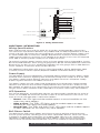
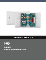
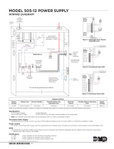
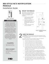
WIRE THE MODULE
Caution: Disconnect all power from the panel before wiring the module.
Failure to do so may result in equipment damage or personal injury.
For power connections, use 22AWG or larger wire. Refer to Figure 4 when
wiring themodule.
1. Connect 505‑12 DC positive to module Terminal 1. Connect 505‑12 DC
negative to module Terminal 2.
2. Connect module Terminal 3to bell output positive. Connect module
Terminal 4to bell output negative.
3. Install the included 10k Ohm EOL resistor across module Terminals 3 and 4.
4. If necessary, wire module Terminals 6and 7to auxiliary trouble indicators.
5. Wire module Terminals 7and 8to N/C trouble contacts.
6. Connect the module 4‑wire harness to the panel LX‑Bus.
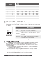
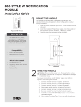
The 867module allows you to specify the cadence of the bell output with the
Ring Style header. To select a bell ring style, place a jumper across the two
appropriate pins on the header as shown in Figure 3. For more information, refer
to Table 2.
SELECT A BELL RING STYLE
SWITCH
TENS ONES
XR150
SERIES
XR550 SERIES
LX500 LX500 LX600 LX700 LX800 LX900
0 0 500 500 600 700 800 900
0 1 501 501 601 701 801 901
0 2 502 502 602 702 802 902
0 3 503 503 603 703 803 903
0 4 504 504 604 704 804 904
... ... ... ... ... ... ... ...
9 5 595 595 695 795 895 995
9 6 596 596 696 796 896 996
9 7 597 597 697 797 897 997
9 8 598 598 698 798 898 998
9 9 599 599 699 799 899 999
Table 1: LX-Bus Addresses
Figure 3: Ring Style
Header Detail
Steady
Pulse
Temporal
California Schools
RING
STYL
Table 2: Bell Ring Style Options
JUMPER
SETTING
BELL CADENCE
Steady On for duration of Bell Cuto time
Pulse
1second on, 1second o for duration of
programmed Bell Cuto time
Temporal
Temporal Code 3as defined in NFPA‑72, section
A‑3‑7.2(a): 0.5 seconds on, 0.5 seconds o, 0.5
seconds on, 0.5 seconds o, 0.5 seconds on, 2
seconds o.
California
Schools
As defined in West's Annotated California Codes,
section 32002: Short, intermittent sounds for
10seconds, then o for 5 seconds.
3
4

867 INSTALLATION GUIDE | DIGITAL MONITORING PRODUCTS 3
ADDITIONAL INFORMATION
Wiring Specifications
DMP recommends using 18 or 22 AWG for all LX‑Bus and Keypad Bus connections.
The maximum wire distance between any module and the DMP Keypad Bus or LX‑Bus
circuit is 10 feet. To increase the wiring distance, install an auxiliary power supply, such
as a DMP Model 505‑12. Maximum voltage drop between a panel or auxiliary power
supply and any device is 2.0 VDC. If the voltage at any device is less than the required
level, add an auxiliary power supply at the end of the circuit.
To maintain auxiliary power integrity when using 22‑gauge wire on Keypad Bus circuits,
do not exceed 500 feet. When using 18‑gauge wire, do not exceed 1,000 feet. Maximum
distance for any bus circuit is 2,500 feet regardless of wire gauge. Each 2,500 foot bus
circuit supports a maximum of 40 LX‑Bus devices.
For additional information refer to the LX‑Bus/Keypad Bus Wiring Application Note
(LT‑2031) and the 710 Bus Splitter/Repeater Module Installation Guide (LT‑0310).
Power Supply
The bell power must be supplied by a regulated, power limited, auxiliary power supply
listed for Fire Protective Signaling with a maximum output of 5Amps at 12or 24VDC.
The power supply output positive connects to module Terminal 1 and power supply
output negative connects to module Terminal 2.
The power supply must be supervised and provide a set of Normally Closed trouble
contacts that connect to the Power Supply Monitor zone (Terminals 7and 8) on the
867module. An open on the supervision circuit causes the Power Supply Monitor LED
to light and an open condition to be reported on the panel supervisory zone address.
LED Operation
For normal operation, all notification devices are connected in parallel on the Style W
circuit. An included 10k Ohm EOL resistor installs at the last device in the circuit. The
Style W circuit LED operation is defined as follows:
• Normal—No LEDs light and the module reports a normal condition on the
supervisory zone address.
• Open or Short—The TRBL LED lights and the module reports an open
condition on the supervisory zone address.
• Ground Fault—The TRBL and GND FAULT LEDs light and the module reports
an open condition on the supervisory zone address.
Bell Silence Switch
The Bell Silence slide switch allows technicians to test or perform maintenance on
the fire system without sounding the fire alarm notification devices. When the switch
is placed in the Bell Silence position, the module TRBL LED turns on and an open
condition is reported on the supervisory zone address. After testing, returning the
silence switch to the Bell Normal position returns the module to normal operation.
5
6
7
8
4
3
2
1
BELL
+ IN
BELL
- IN
BELL
+ OUT
BELL
- OUT
BELL
TRBL
BELL
TRBL
PS
MON
MON
ATN
BELL SILENCE
BELL NORMAL
MODEL
867
PS
TRBL
TENS ONES
TENS
SUPERVISORY ADDR
BELL ADDRESS
ONES
RING
STYL
DATA
RED
BLACK
BELL
TRBL
GND
FAU LT
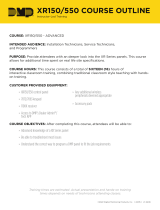
Trouble and Ground Fault LEDs
Power Supply Trouble and Data LEDs
Ring Style Header
Bell Address Switches
Supervisory Address Switches
Bell Silence Slide Switch
From 505-12 DC +
To N/C Trouble Contact
To LX-Bus
From 505-12 DC –
To Trouble Indicator (optional)
To Trouble Indicator (optional)
To N/C Trouble Contact
+
–
To Bell Output –
To Bell Output +
10k Ω EOL
S
S
S
S
S
= Supervised Circuit
All circuits are power limted.
Figure 4: Wiring Connections

Designed, engineered, and
manufactured in Springfield,
MO using U.S. and global
components.
LT-0178 1.02 20145
867 STYLE W LX-BUS
NOTIFICATION MODULE
Specifications
Operating Voltage
LX-Bus 8.0 to 15.0 VDC
Operating Current
LX-Bus 30mA maximum
Bell Power 30mA standby,
86mA maximum
Alarm Switching
Current 5 Amps @ 12 or 24 VDC
Ordering Information
867 Style W LX-Bus Notification Module
Accessories
308 10k Ohm Replacement Resistor
505-12 Series Power Supplies
Compatibility
XR150/XR550 Series panels
505-12 Series Power Supplies
Certifications
California State Fire Marshal (CSFM)
FCC Certified Part 15
New York City (FDNY COA #6167)
Underwriters Laboratory (UL) Listed
ANSI/UL 1023 Household Burglar
ANSI/UL 985 Household Fire Warning
ANSI/UL 864 Fire Protective Signaling
5
6
7
8
4
3
2
1
BELL
+ IN
BELL
- IN
BELL
+ OUT
BELL
- OUT
BELL
TRBL
BELL
TRBL
PS
MON
MON
ATN
BELL SILENCE
BELL NORMAL
MODEL
867
PS
TRBL
TENS ONES
TENS
SUPERVISORY ADDR
BELL ADDRESS
ONES
RING
STYL
DATA
BELL
TRBL
GND
FAULT
INTRUSION•FIRE•ACCESS•NETWORKS
2500 North Partnership Boulevard
Springfield, Missouri 65803-8877
800.641.4282 | DMP.com
FCC INFORMATION
This device complies with Part 15 of the FCC Rules. Operation is subject to the following two
conditions:
1. This device may not cause harmful interference, and
2. this device must accept any interference received, including interference that may cause
undesired operation.
The antenna used for this transmitter must be installed to provide a separation distance of at
least 20 cm (7.874 in.) from all persons. It must not be located or operated in conjunction with
any other antenna or transmitter.
Changes or modifications made by the user and not expressly approved by the party
responsible for compliance could void the user’s authority to operate the equipment.
Note: This equipment has been tested and found to comply with the limits for a Class B
digital device, pursuant to part 15 of the FCC Rules. These limits are designed to provide
reasonable protection against harmful interference in a residential installation. This
equipment generates, uses and can radiate radio frequency energy and, if not installed
and used in accordance with the instructions, may cause harmful interference to radio
communications. However, there is no guarantee that interference will not occur in a
particular installation. If this equipment does cause harmful interference to radio or
television reception, which can be determined by turning the equipment o and on, the
user is encouraged to try to correct the interference by one or more of the following
measures:
1. Reorient or relocate the receiving antenna.
2. Increase the separation between the equipment and receiver.
3. Connect the equipment into an outlet on a circuit dierent from that to which the
receiver is connected.
4. Consult the dealer or an experienced radio/TV technician for help.
© 2020
-
 1
1
-
 2
2
-
 3
3
-
 4
4


DMP 867 Style W LX-BUS Notification Module Installation guide
- Category
- Fire protection
- Type
- Installation guide
- This manual is also suitable for
Ask a question and I''ll find the answer in the document
Finding information in a document is now easier with AI
Related papers
-
 Digital Monitoring Products 711 Zone Expansion Module Installation guide
-
 DMP Electronics 712-8 Installation guide
-
 Digital Monitoring Products 714 Zone Expansion Module Installation guide
-
 DMP XR150 Owner's manual
-
DMP XR150-550 Operating instructions
-
Digital Monitoring Products 730 3-Port Switch Installation guide
-
 DMP Electronics 893A Dual Phone Line Module Installation guide
-
 DMP Electronics 893A Dual Phone Line Module Installation guide


Other documents
-
 Digital Monitoring Products 866 Style W Notification Module Installation guide
-
 Digital Monitoring Products 505-12 POWER SUPPLY Product information
-
 DMP Electronics XR500E SERIES Installation guide
-
 Digital Monitoring Products 721T TERMINAL BLOCK MODULE Installation guide
-
 DMP Electronics 865 Installation guide
-
 DMP Electronics XR550CAN Series Installation guide
-
 DMP Electronics 865 Installation guide
-
 DMP Electronics XR550 series Installation guide
-
 Digital Monitoring Products XR150/XR550 Canadian Series Control Panel Installation & Programming Guides
-
 DMP Electronics XR2500F User manual


