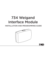
Digital Monitoring Products 730 3-Port Switch Installation guide

Type
Installation guide

This manual is also suitable for

INSTALL THE 730
The 730 is designed to easily mount inside the panel enclosure
using the standard 3‑hole mounting pattern. See Figure 2.
1. Mount the plastic standos to the enclosure using the three
included Phillips head screws.
2. Insert the screws from the outside of the enclosure through
the holes and into the plastic stando that mounts on the
inside of the enclosure.
3. Snap the 730 onto the standos.
4. Use 22 AWG wire to connect DC+ on the 730 to terminal 7
on the panel. Connect DC‑ to panel terminal 10.
5. Connect the 357‑2 Cat 5 cable from the Network port on
the panel to the PANEL port on the 730.
6. Connect the premises network used for communication to
the Central Station to the SCS port on the 730.
7. Connect the 734N network to the DOORS port on the 730.
730 3-PORT SWITCH
Installation Guide
Model 730
3-Port Switch
357-2
SCS DOORS
+ DC -
PANEL
PWR
AC
1 2 3 4 5 6 8 11 12 13 14 15 16 17 18 199 20 21 22 23 24 25 26 27 28
+B BELL GND SMK GNDRED YEL GRN BLK Z1 Z2 Z3 Z4 Z5 Z6 Z7 Z8 Z9+ Z9– Z10+ Z10–AC –B GND GND GNDGND
XR550 Series
Panel
Phone Line
Reset
Tamper
Battery
Start
Power
LED
Activity LED
Ethernet
Outputs 3-6
Output 1 Output 2
Out1 Out2
Link LED
Cell Module
Load
s
PROG
7 10
Figure 2: 730 Installation
SCS DOORS
+ DC -
PANEL
PWR
Figure 1: PCB Layout
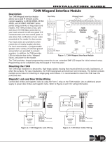
DESCRIPTION
The Model 730 3‑Port Switch
provides a separate data network
where network‑enabled access
control devices are installed.
When connected to an
XR150/XR550, the 730 isolates
two network ports with IP’s
provided by the premises
network.
With the use of a separate router
the DOORS network can be
configured to an entirely dierent
IP scheme while maintaining
communication with the panel.
Alarm messages are sent through
the premises network to the
Central Station SCS‑1R or SCS‑VR
receiver using the SCS network
port of the 730.
Access control messages are
only sent to a separate network
of 734N or 734N‑POE Access
Control Modules through the
DOORS port of the 730.
Compatibility
XR150/XR550 Series
Control Panels
734N Wiegand Interface
Module
What Is Included?
Model 730 3‑Port Switch
357‑2 Cat‑5 Cable
Hardware pack
LED Operation
Next to each port an LED flashes to indicate active network
communication.
1
INTRUSION FIRE ACCESS NETWORKS
2500 North Partnership Boulevard
Springfield, Missouri 65803-8877
800.641.4282 | DMP.com
730 3-PORT SWITCH Certifications
FCC Part 15
ETL Listed ITE Information Technology Equipment
UL 60950-1
Specifications
Power Requirements
Operating Voltage 12 VDC
Current Draw 80 mA
Dimensions 5” x 3”
SCS Port 10/100 BASE-T
DOORS Port 10/100 BASE-T
PANEL Port 100 BASE-T
Designed, engineered, and
manufactured in Springfield, MO
using U.S. and global components.
LT-1280 1.01 21011
© 2021
XR550 Series Panel
734N Wiegand
Interface Module
734N
Network
Isolated Network
Internet
Model 730
3-Port Switch
SCS DOORS
+ DC -
PANEL
PWR
AC
1 2 3 4 5 6 8 11 12 13 14 15 16 17 18 199 20 21 22 23 24 25 26 27 28
+B BELL GND SMK GNDRED YEL GRN BLK Z1 Z2 Z3 Z4 Z5 Z6 Z7 Z8 Z9+ Z9– Z10+ Z10–AC –B GND GND GNDGND
Phone Line
Reset
Tamper
Battery
Start
Power
LED
Activity LED
Ethernet
Outputs 3-6
Output 1 Output 2
Out1 Out2
Link LED
Cell Module
Load
s
PROG
7 10
SCS-1R
Central Station
Receiver
SCS-VR
Centeral Station
Receiver
OR
Figure 3: Model 730 Application
734N NETWORK CONFIGURATION
2
SCS DOORS
+ DC -
PANEL
PWR
XR550 Series Panel
734N Wiegand
Interface Module
734N
Network
Isolated Network
Internet
Model 730
3-Port Switch
SCS DOORS
+ DC -
PANEL
PWR
AC
1 2 3 4 5 6 8 11 12 13 14 15 16 17 18 199 20 21 22 23 24 25 26 27 28
+B BELL GND SMK GNDRED YEL GRN BLK Z1 Z2 Z3 Z4 Z5 Z6 Z7 Z8 Z9+ Z9– Z10+ Z10–AC –B GND GND GNDGND
Phone Line
Reset
Tamper
Battery
Start
Power
LED
Activity LED
Ethernet
Outputs 3-6
Output 1 Output 2
Out1 Out2
Link LED
Cell Module
Load
s
PROG
7 10
Router
SCS-1R
Central Station
Receiver
SCS-VR
Centeral Station
Receiver
OR
Customer-Provided IP Address Setup
All the information in
Section 2 applies to
this configuration.
However, with this
configuration, the
734Ns receive their IPs
from the router, not
from the customer’s
network. This allows
the 734N network to
be entirely separate
from the customer’s
network.
Router-Provided IP Address Setup
The 734N network
connects to the DOORS
port of the 730.
The local 734N IP
Address must be a unique
address on the end‑users
network.
The Subnet Mask
programming of the 734N
must be the same as
programmed at Subnet
Mask on the XR150/XR550.
Figure 4: Model 730 Application with Router
The 734N Panel IP
Address must be
programmed with the address of the
XR150/XR550 local IP address.
  • Page 1 1
  • Page 2 2

Digital Monitoring Products 730 3-Port Switch Installation guide

Type
Installation guide
This manual is also suitable for

Ask a question and I''ll find the answer in the document

Finding information in a document is now easier with AI