Workrite 2-Leg 120 Deg. 46″-48″Wx23″-24″D, T464623T Installation guide
- Type
- Installation guide

Workrite Ergonomics | 800.959.9675 www.workriteergo.com 1500320 Rev B
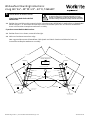
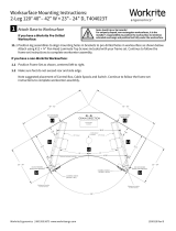
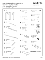
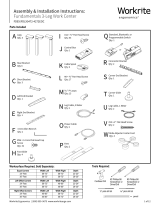
Worksurface Mounting Instructions:
2-Leg 120° 46"– 48" W × 23"– 24" D, T464623T
Attach Base to Worksurface
If you have a Workrite Pre-Drilled
Worksurface:
1.1 Position leg assemblies to align mounting holes in brackets to pre-drilled holes in worksurface as shown below.
Attach using #12 × ¾" Pan Head Laminate Top Screws included with your frame set. Continue to follow the
frame set instructions to complete workcenter assembly.
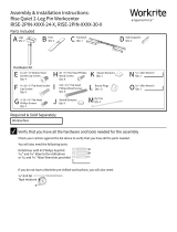
If you have a non-Workrite Worksurface:
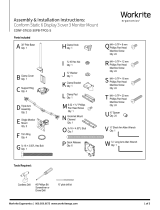
1.1 Position Frame Set as shown, centered le to right.
1.2 Make sure feet do not exceed rear edge.
Note suggested placement of Control Box, Cable Spools and Switch. Continue to follow the frame set
instructions to complete workcenter assembly.
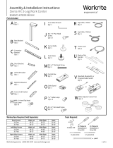
DO NOT EXCEED
FRONT AND SIDE EDGE
120°
CONTROL SWITCH
(OPTION - RIGHT)
CONTROL SWITCH
(OPTION - LEFT)
48.98
56.24
15°
15°
GRAIN DIRECTION
DO NOT EXCEED
FRONT AND SIDE EDGE
29” D Foot
Cable Spool
location
Control Box
location
29” D Foot
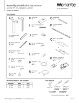
Distance between brackets
Distance between brackets
Reference location
for front of foot.
Reference location
for front of foot.
DO NOT EXCEED
REAR EDGE
DO NOT EXCEED
REAR EDGE
46” - 48”
23” - 24” 23” - 24”
46” - 48”
15.51
5.60
15.51
5.60
1Note: Avoid trip or tip hazards!
For uniquely shaped, non-rectangular worksurfaces, it is the
installer's responsibility to position the worksurface to minimize
extended overhangs and position feet fully under the worksurface.
1.1
1.1
1.1
1.21.2
1.2 1.2
-
 1
1

Workrite 2-Leg 120 Deg. 46″-48″Wx23″-24″D, T464623T Installation guide
- Type
- Installation guide
Ask a question and I''ll find the answer in the document
Finding information in a document is now easier with AI
Related papers
-
 Workrite Ergonomics 2-Leg 120 Deg. 40″-42″Wx23″-24″D, T404023T Installation guide
-
 Workrite Ergonomics Fundamentals EX/LX Benching System, 2 Stations Installation guide
-
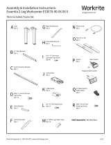
 Workrite Ergonomics Essentia 2-Leg ES3E30-48 30″-48″ Installation guide
-
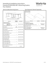 Workrite Ergonomics Essentia Benching System Installation guide
-
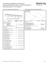
 Workrite Ergonomics Essentia Benching System Installation guide
-
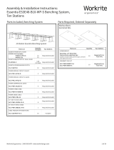
 Workrite Ergonomics Essentia Benching System Installation guide
-
 Workrite Ergonomics Essentia Benching System Installation guide
-
 Workrite Ergonomics Essentia 2-Leg ES3E78-90 78″-90″ Installation guide
-
 Workrite Ergonomics Essentia 3-Leg ES3E7890-4248OC 78″-90″ X 42″-48″ Installation guide
-
 Workrite Ergonomics Rise Quiet 2-Leg Pin Installation guide


Other documents
-
 ISE SB-ASC2-3-23-SM-DRMS Assembly And Installation Instructions Manual
-
 Workrite Ergonomics Sierra HX 3-Leg Installation guide
-
 Workrite Ergonomics Sierra HX 2-Leg Installation guide
-
 Workrite Ergonomics Fundamentals EX/LX 3-Leg 54-72″, 42-72″ Installation guide
-
Ergotron 85-010-087 Datasheet
-
 Workrite Ergonomics BT-PROSWITCH User manual
-
 Workrite Ergonomics Conform ST 633 Installation guide
-


