Page is loading ...

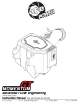
Cold Air Intake System
Instruction Manual P/N: 50-70078D / 50-70078R__ __ ________________________
Make: Ford Model: Bronco Sport Year: 2021-2022 Engine: I3-1.5L (t)
Make: Ford Model: Escape Year: 2020-2022 Engine: I3-1.5L (t)
1
2

Page 2
• Please read the entire instruction manual before proceeding.
3
• Ensure all components listed are present.
4
• For technical support please call 951-493-7185.
5
• Ensure you have all necessary tools before proceeding.
6
• Do not attempt to work on your vehicle when the engine is hot.
7
• Retain factory parts for future use.
8
9
Label
Qty.
Description
Part Number
A1
1
Air Filter (Pro 5R)
20-91202R
A2
1
Air Filter (Pro DRY S)
20-91202D
B
1
Tube, Driver
05-5070078B1
C
1
Housing
05-5070078B2
D
1
Screw, Flange Hex Head: M6 x 1.00 x 25mm
03-50774
E
1
Grommet, Rubber
03-50167
F
1
Fitting, Air Temp Sensor
05-01454
G
1
Clamp, 044 (2-5/16" - 3-1/4")
03-50019
H
1
Coupling, Silicone Bellow Rdr: (3"x2-5/8")ID X 3"L
05-01730
J
1
Clamp, 048 (2-9/16" - 3-1/2 ")
03-50007
K
1
Plug, Silicone: 2.25" Dia
05-01482
Installation will require the following tools:
10
Panel clip remover, 7mm & 8mm nut driver, 10mm deep socket and driver, 4mm and 10mm socket and
11
driver
12
13
14
15
Warranty Information available at https://afepower.com/contact#warranty
16
17
18
19
20
Emissions Disclaimer: This product is not currently CARB exempt and is not available for purchase in
21
California or for use on any vehicle registered with the California Department of Motor Vehicles.
22

Page 3
23
24
25
26
27
28
29

Page 4
Refer to Figure A for Step 1
30
Step 1: Using a panel clip remover, remove the two (x2) panel clips 1 holding the scoop shield. Remove
31
the scoop shield and set it aside with the clips.
32
33
34
35
36
37
38
REMOVAL
Figure A
1

Page 5
Refer to Figure B for Steps 2-4
39
Step 2: Using a 7mm nut driver, loosen the clamp 2 at the factory intake tube. Detach the factory rubber
40
tube from the factory intake tube.
41
Step 3: Disconnect the IAT sensor electrical connector 3 .
42
Step 4: Release the clips 4 and position the wiring harness aside.
43
44
45
3
REMOVAL
Figure B
4
2

Page 6
Refer to Figure C for Step 5
46
Step 5: Detach and remove the factory airbox from the isolators 5 . If the isolators are pulled out and are
47
stuck in the lower half of the factory airbox, remove them and insert them back on the mounting bracket.
48
49
REMOVAL
Figure C
5

Page 7
Refer to Figure D for Step 6-8
50
Step 6: Using a 10mm deep socket and driver, remove the nut 6 holding the factory intake tube.
51
Step 7: Using a 4mm socket and driver, remove the stud 7 and replace it with the provided M6x25mm
52
screw. Tighten the screw using a 10mm socket and driver.
53
Step 8: Remove the rubber isolator 8 from the hose.
54
55
56
57
58
REMOVAL
Figure D
6
7
8

Page 8
Refer to Figure E for Steps 9-11
59
Step 9: Install the aFe POWER housing into the vehicle. Make sure housing pins are aligned and all the way
60
through the isolators.
61
Step 10: Install the air cleaner scoop shield and the two (x2) clips 9 while snapping into the aFe POWER
62
housing.
63
Step 11: Install the supplied aFe plug 10 on the side of the aFe POWER housing as shown.
64
NOTE: This plug is accessible to be removed and installed at any time to increase airflow and engine
65
sound if desired.
66
67
REMOVAL
Figure E
9
10
10

Page 9
Refer to Figure F for Step 12
68
Step 12: Slide the aFe POWER filter and clamp into the aFe POWER housing and push them in until it locks
69
into place. Do not tighten the clamp at this time.
70
REMOVAL
Figure F

Page 10
Refer to Figure G for Steps 13-14
71
Step 13: Install the supplied coupling 11 with the small end onto the factory intake tube with the supplied #44
72
clamp 12 and tighten the clamp using an 8mm nut driver.
73
Step 14: Place the supplied #48 clamp 13 onto the coupling and slightly snug so it will not fall off.
74
75
76
12
INSTALL
Figure G
13
11

Page 11
Refer to Figure H for Steps 15-17
77
Step 15: Remove the IAT sensor 14 from the factory airbox by rotating ¼ turn counterclockwise and gently
78
pulling out.
79
Step 16: Install the provided grommet and temp sensor fitting 15 into the the filter side of the aFe POWER
80
intake tube.
81
NOTE: Lubricant can be used to facilitate the installion of the fitting into the grommet.
82
Step 17: Install the IAT sensor into the temp sensor fitting by rotating ¼ turn clockwise until it locks into
83
place. Rotate the temp sensor fitting to have mounting tab 16 pointing in the direction of the tube opening
84
as shown.
85
86
15
16
INSTALL
Figure H
14

Page 12
Refer to Figure I for Steps 18-20
87
Step 18: Install the aFe POWER intake tube into the coupling first and then into the air filter. Align the tube
88
correctly and tighten the clamps using an 8mm nut driver.
89
Step 19: Connect the IAT sensor electrical connector 17 .
90
Step 20: Check all the components are tight and secure. Your installation is now complete. Thank you for
91
choosing aFe POWER!
92
93
94
NOTE: Check all bolts, clamps, and connectors after 100-200 miles.
95
INSTALL
Figure I
17

Page 13
96
97
98
99
100
101
102
103
104
105
106
Page left blank intentionally
107
108
109
110
111
112
113
114
115
116
117
118

Page 14
119
120
121
122
123
124
125
126
127
128
129
Page left blank intentionally
130
131
132
133

Page 15
134
135
136
137
138
139
140
141
142
Page left blank intentionally
143
144
145
146

/