Page is loading ...

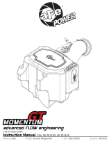
advanced FLOW engineering
Instruction Manual P/N: 51-12602 & 54-12602
Make: Jeep Model: Commander Year: 2006-2009 Engine: V8-4.7L
Make: Jeep Model: Grand Cherokee Year: 2005-2009 Engine: V8-4.7L

Label Qty. Description Part Number
A1 1 Pro DRY S Air Filter 21-40011 (Gray Media)
A2 1 Pro Pro 5R Air Filter 24-40011 (Blue Media)
B 1 Housing 05-00722
C 1 Tube 05-12602B1
D 1 Coupler hump, 3.5x3" 05-00565
E 1 Coupler reducer, 3.25x3" 05-00636
F 3 Clamps, #056 03-50009
G 1 Clamps, #048 03-50007
H 2 Clamps, mini #006 03-50025
I 1 Grommet 03-50033
J 2 Screw, 1/4-20x1" 03-50122
K 2 Nut, 1/4-20 03-50073
L 4 Washer, flat 03-50070
M 4 Screw, M6 03-50113
N 1 Tube 05-00748
O 1 Cover 05-00722
P 1 Hose 5/8", 18" long 05-00069
Installation will require the following tools:
Flat head screw driver, Phillips screw driver, 8mm socket, 10mm socket, Rachet & 5/16 nut driver, & 4mm
hex key
Note: Legal in California for use on race vehicles only. The use of this device on vehicles used on public
streets or highways is strictly prohibited in California and others states that have adopted California
emission regulations.
• Please read the entire instruction manual before proceeding.
• Ensure all components listed are present.
• If you are missing any of the components, call customer support at 951-493-7100.
• Ensure you have all necessary tools before proceeding.
• Do not attempt to work on your vehicle when the engine is hot.
• Disconnect the negative battery terminal before proceeding.
• Retain factory parts for future use.
Page 2

aFepower.com
A1 A2
B
C
Page 3
FG
L
NDE
K M J I
O
H
P

Refer to Figure A
Step 1: Remove Engine Cover.
Step 2: Disconnect the Temp Sensor from OE intake tube 1 .
Step 3: Disconnect the Engine vacuum line connected to the OE intake housing 2 .
Step 4: Loosen the throttle body clamp 3 and OE intake tube from plenum.
Step 5: Loosen top portion of the OE intake by unclipping the tabs from the housing 4 .
REMOVAL
Page 4
3
2
4
3
1
4
Figure A

Refer to Figure B
Step 6: Remove OE intake. (Throttle body side first followed by lifting the top portion of the OE intake.
Step 7: Remove the OE Filter from the lower portion of the housing 5 .
Step 8: Remove Vacuum line connected to the engine valve cover 6 .
Step 9: Remove the temp sensor from the OE intake tube and save for later use.
REMOVAL
aFepower.com
Page 5
5
6
Figure B

Refer to Figure C
Step 10: Remove the vacuum hose from the Plastic portion of the vacuum line with the mini clamp.
*This will be re used later on in the installation of the aFe intake 7 .
*Grand Cherokee models disconnect the 1/2" line from the
T-vacuum fitting that is attached to the OE intake tube.
Figure C
INSTALL
Page 6
7

Refer to Figure D
Step 11: Assemble the aFe housing with the aFe intake tube (05-00748) using the ¼-20 screw, washers
and the ¼-20 self-locking nut.
Step 12: Install hump coupler with clamps. Tighten only the tube side.
Figure D
INSTALL
aFepower.com
Page 7

Refer to Figure E
Step 13: Install the aFe housing and intake over the lower portion of the OE housing. Snap in place
using the tabs to hold down the aFe housing.
Step 14: Install the aFe filter on the aFe housing.
Step 15: Install the aFe Vacuum line on the valve cover and then to the aFe intake tube 8 .
*Grand Cherokee install the 5/8" hose that was provided from the aFe intake tube to the
T-vacuum fitting and tighten down with the provided mini clamps.
Page 8
Figure E
INSTALL
8

aFepower.com
Page 9
Refer to Figure F
Step 16: Install the aFe grommet onto the aFe intake tube (05-12602B1) followed by the temp sensor
from the OE intake tube.
Step17: Install the reducer coupling onto the shorter end of the tube. (Place the clamps over the
coupling but do not tighten 9 .
Step 18: Install the assembled intake tube onto vehicle by sliding the end without the coupling into the
other end of the aFe intake tube with coupling, followed by inserting it to the throttle body.
Step 19: Install aFe housing cover using the M6 screws.
Step 20: Reconnect the temp sensor.
Step 21: Tighten all clamps.
Figure F
INSTALL
9

Page 10
INSTALL
12
Page left blank intentionally

Page 11
Page left blank intentionally

Page 12
Page left blank intentionally

Page 13
Page left blank intentionally

To purchase any of the items above, view airflow charts, dyno graphs, photos, and video; please go to aFepower.com.
Page 14
Pro DRY S Air Filter
P/N: 21-40011 P/N: 90-50001
P/N: 90-50501 P/N: 49-48052
P/N: 90-59999
Pro DRY S Restore Kit Blue Aerosol Restore Kit
Blue Squeeze Restore Kit Cat-Back Exhaust
Programmer
P/N: 77-46202
Pro 5R Air Filter
P/N: 24-40011
P/N: 40-10083
aFe Power Hat

Warranty
aFe warrants their intake systems to be free of defects from
workmanship and materials for a period of two (2) years, provided the
intake system was: A) installed in an aFe recommended application
according to aFe installation instructions; and B) the air filter has
been properly cleaned utilizing an aFe cleaning solution and oil (not
applicable on Pro DRY S filters). Damage from abuse, improper cleaning,
improper oil and improper installation or from open flame is not covered by this
limited warranty. In the event of a defect of an aFe product within the period
covered by this limited warranty, the purchaser can return the product
to the dealer where it was purchased or send the product to aFe at the
address listed on the back after obtaining a Return Good
Authorization (RGA) number from aFe. The original register receipt will be
required as proof of purchase. Purchaser will be entitled to a refund of the entire
purchase price or a replacement of the product at aFe’s discretion.
Purchaser shall be responsible for the cost of shipping the defective
product to aFe. An RGA number can be obtained by calling aFe
customer service. Products shipped without an RGA number will be
refused. A refund or replacement of the product shall be the sole remedy
available under this limited warranty and aFe shall not be responsible for
consequential or incidental damages. (Some states do not allow this
exclusion or limitation of incidental or consequential damages, so the
above limitation or exclusion may not apply). This warranty gives you
specific legal rights, and you may have other rights, which vary from
state to state.
aFepower.com
Page 15

advanced FLOW engineering, inc.
252 Granite Street Corona, CA 92879
TEL: 951.493.7100 • TECH: 951.493.7100 x23
E-Mail:Tech@aFepower.com P/N: 06-80671
/


