Page is loading ...

Edelbrock E-Force Supercharger
2005-10 6.1L HEMI / 2006-10 5.7L HEMI
Part #1530, 1531, 1532, 1533, 1536 & 1537

©2016 Edelbrock LLC
Part #1530, 1531, 1532, 1533, 1536 & 1537
Brochure #63-1530
Rev. 8/2/16 - QT
Edelbrock Hemi Supercharger System
2005 - 2010 Dodge/Chrysler Vehicles
Installation Instructions
Page 1
Thank you for purchasing the Edelbrock Hemi Supercharger System for various Chrysler/Dodge vehicles. The Edelbrock
E-Force Supercharger System for the 2005 to 2011 Hemi utilizes Eaton’s new Gen VI TVS Supercharger rotors, featuring a
four lobe design with a full 160° of twist for maximum flow, minimum temperature rise, quiet operation, and the reliability
for which Eaton is known. The Edelbrock Supercharger is a complete system that maximizes efficiency and performance
by minimizing air restriction into, and out of, the supercharger. This results in maximum airflow, with minimal temperature
rise and power consumption. The supercharger housing itself is integrated into the intake manifold for a seamless design
with minimal components, eliminating the possibility of vacuum leaks between gasket surfaces. The system also utilizes
a front drive, front inlet configuration giving it the shortest, least restrictive inlet path on the market. The supercharger is
inverted, expelling the air upward. Air pressure then builds in the plenum, before being pushed through the intercooler,
oriented horizontally, above the supercharger outlet. After passing through the intercooler core, the air travels through the
long runners, which route straight down into the cylinder head ports. This configuration allows for a compact package
that can fit under the stock hood and cowl of the vehicles for which it was designed, without sacrificing runner length, or
intercooler area. The E-Force supercharger features a uniquely styled plenum, and includes matching side covers. The
Edelbrock supercharger provides neck snapping performance that is safe to operate on a completely stock engine. It can
be had with an optional 5-year 100,000 mile warranty so that there are no worries when installing it on a brand new car.
INTRODUCTION
TOOLS AND SUPPLIES REQUIRED
z Jack and Jack Stands OR Service Lift
z Panel Puller
z Ratchet and Socket Set including: 7mm, 8mm, 10mm
(standard, deep and swivel), 11mm, 12mm (deep),
13mm, 15mm, 18mm, 21mm (deep), 24mm
z Wrenches including: 8mm, 18mm, 27mm
z 1/2” Breaker Bar
z Flat Blade & Philips Screwdrivers
z Compressed Air
z Allen Wrenches including: 5mm, 6mm, 8mm
z 4” Long 6mm Allen Socket
z Mechanic’s Wire
z Chrysler Crank Pulley Installation Tool #8512A OR
Equivalent
z Chrysler Fuel Pump Lock Ring Remover/Installer
#9340 OR Equivalent
z Side Cutters
z 3 Jaw Pulley Puller
z Chrysler tool #8513A or equivalent
z 3/8” & 5/16” Fuel Line Removal Tools
z Torque Wrench
z Needle Nose Pliers
z Pliers OR Hose Clamp Removal Tool
z Pneumatic or Power Drill
z Impact Wrench
z Blue & Green Loctite Retaining Compound or equivalent
z O-ring Lube
z Masking Tape

©2016 Edelbrock LLC
Part #1530, 1531, 1532, 1533, 1536 & 1537
Brochure #63-1530
Rev. 8/2/16 - QT
Edelbrock Hemi Supercharger System
2005 - 2010 Dodge/Chrysler Vehicles
Installation Instructions
Page 2
Due to the complexity of the Edelbrock E-Force Supercharging system, it is recommended that this system only
be installed by a qualified professional with access to a service lift, pneumatic tools, and a strong familiarity
with automotive service procedures. To qualify for the optional supplemental warranty, it is necessary to have
this system installed by a Certified ASE Technician at a licensed shop, Chrysler Dealership, or an Authorized
Edelbrock Installer. Failure to do so will void and/or disqualify any and all optional supplemental warranties
offered with this system. Please contact the Edelbrock Technical Support department if you have any questions
regarding this system and/or how your installer of choice will affect any warranty coverage for which your vehicle
may qualify.
Proper installation is the responsibility of the installer. Improper installation will void all
manufacture’s standard warranties and may result in poor performance and engine or vehicle
damage.
Inspect all components for damage that may have occurred in transit before beginning
installation. If any parts are missing or damaged, contact Edelbrock Technical Support, not your
parts distributor.
Before beginning installation, use the enclosed checklist to verify that all
components are present in the box then inspect each component for damage
that may have occurred in transit. If any parts are missing or damaged,
contact Edelbrock Technical Support, not your parts distributor.
WARNING: Installation of this supercharger will result in a significant change to the
performance characteristics of your vehicle. It is highly recommended that you take some
time to familiarize yourself with the added power, and how it is delivered, in a controlled
environment. Take extra care on wet and slippery roads, as the rear tires will be more likely
to lose traction, with the added power. It is never recommended to turn off your vehicles
traction control system.
IMPORTANT WARNINGS
Edelbrock periodically releases improved versions of the calibration file found on the supplied
handheld programmer. Check the website to ensure you have the latest version, as described in the
Test Flash Procedure on Page #9.
NOTE: If you get the message on your InTune programmer that reads: “This vehicle needs an update
Download here: www.diablosport.com/dcx.” This is because the programmer needs to update the
vehicle’s stock calibration file because the vehicle currently has an older calibration that is not
supported by the programmer, this does not mean that the programmer itself needs an update.
Please go to www.diablosport.com/dcx and it will instruct you how to update the calibration for your
vehicle.

©2016 Edelbrock LLC
Part #1530, 1531, 1532, 1533, 1536 & 1537
Brochure #63-1530
Rev. 8/2/16 - QT
Edelbrock Hemi Supercharger System
2005 - 2010 Dodge/Chrysler Vehicles
Installation Instructions
Page 3
91 octane or higher gasoline is required at all times. If your vehicle has
been filled with anything less, it must be run until dry and refilled with 91
or higher octane gasoline twice prior to installation.
Any failures associated with not using premium 91 octane gasoline or
higher, will be ineligible for warranty repairs.
IMPORTANT WARNINGS cont’d
Edelbrock Authorized Installer Disclaimer
Authorized installers of Edelbrock products are independent companies over which Edelbrock has no right of control. Edelbrock LLC makes no claims
regarding the abilities, expertise or competency of individual employees of any authorized installer. Each authorized installer is an independent company
and makes its own independent judgments. Edelbrock LLC specifically disclaims any responsibility to any party including third parties for the actions, or
the failure to act, of individuals, agents or a company authorized in the installation of Edelbrock LLC products.
Any equipment that directly modifies the fuel mixture or ignition timing of the engine can cause severe engine
damage if used in conjunction with the Edelbrock E-Force Supercharger System. This includes, but is not limited
to: ignition boxes, air/fuel controllers, OBDII programmers, and any other device that modifies signals to and/or
from the ECU. Aftermarket bolt-on equipment such as underdrive pulleys or air intake kits will also conflict with
the operation of the supercharger and must be removed prior to installation. Use of any of these products with
the E-Force Supercharger could result in severe engine damage.
Any previously installed aftermarket tuning equipment must be removed and the vehicle returned
to an as stock condition before installing the supercharger.
SRT8 Challengers and SRT8 Magnums using kit #1536 may need to modify or remove the under
hood air duct as it may interfere with the E-Force Supercharger.
NOTE: Supercharger Systems with Serial Number greater than 3632 (5.7L Applications) and 3676
(6.1L Applications) are supplied with the new Diablo InTune programmer. If your system is supplied
with the Diablo Predator programmer please download the Diablo Predator Flashing Procedure by
clicking the link below:
http://www.edelbrock.com/automotive_new/mc/superchargers/pdf/diablo_flash_procedure.pdf

©2016 Edelbrock LLC
Part #1530, 1531, 1532, 1533, 1536 & 1537
Brochure #63-1530
Rev. 8/2/16 - QT
Edelbrock Hemi Supercharger System
2005 - 2010 Dodge/Chrysler Vehicles
Installation Instructions
Page 4
Bag #1
Bag #2
(12x) - M6 x 1.0 x 30mm Hex Flange Bolt
(4x) - M6 x 1.0 x 40mm Hex Flange Bolt
(2x) - M8 x 1.25 x 20mm Hex Flange Bolt
(1x) - M8 x 1.25 x 90mm Socket Head Bolt
(1x) - M8 x 1.25 x 75mm Socket Head Bolt
(1x) - M8 x 1.25 Hex Flange Nut
(1x) - M10 x 1.5 x 65mm Hex Flange Bolt
(2x) - M8 Washer
INSTALLATION HARDWARE IDENTIFICATION GUIDE (Not All Parts Are To Scale)
(1x) - M10 x 1.5 x 45mm Countersunk Bolt
(2x) - M6 x 1.0 x 20mm Socket Head Bolt
(1x) - M8 x 1.25 x 40mm Socket Head Bolt
(2x) - Nose Support Block
(1x) - Throttle Body O-Ring (Included, but not shown)
(2x) - Spacer, 1.00”
(2x) - M6 x 1.0 x 40mm Hex Flange Bolt
(1x) - M8 x 1.25 x 45mm Countersunk Bolt

©2016 Edelbrock LLC
Part #1530, 1531, 1532, 1533, 1536 & 1537
Brochure #63-1530
Rev. 8/2/16 - QT
Edelbrock Hemi Supercharger System
2005 - 2010 Dodge/Chrysler Vehicles
Installation Instructions
Page 5
Bag #3
(3x) - M8 x 1.25 x 30mm Hex Flange Bolt
(4x) - M6 x 1 x 25mm Hex Flange Bolt
(4x) - M6 x 1 x 16mm Hex Flange Bolt
(1x) - 15/64” High Speed Steel Drill Bit
(1x) - .2500” Reamer
Bag #4
(1x) - 1/4” x 1/2” Steel Dowel
(2x) - M8 x 1.25 Hex Flange Nut
(4x) - 3/8” Hose Clamp
(8x) - 3/4” Hose Clamp
(1x) - 3/8” Hose Coupler
(1x) - Crank Pinning Drill Guide
(8x) - Small Push Pin
(1x) - M5 Lock Nut
(6x) - Large Push Pin
(1x) - Hose Support Bracket
(1x) - Cushion Clamp
(1x) - M5 x 16mm Hex Flange Bolt

©2016 Edelbrock LLC
Part #1530, 1531, 1532, 1533, 1536 & 1537
Brochure #63-1530
Rev. 8/2/16 - QT
Edelbrock Hemi Supercharger System
2005 - 2010 Dodge/Chrysler Vehicles
Installation Instructions
Page 6
Bag #5
Bag #6
(1x) - #8-32 Airbox Bumper
(1x) - Airbox
Grommet Adapter
(7x) - M6 x 1.0 x 16mm Hex Flange Bolt
(1x) - Airbox Bracket
(2x) - 1/4-20 x 1/2” 3/8” Hex Flange Bolt
(4x) - M6 x 1 x 12mm
Socket Head Bolt
(4x) - Coil Cover
Ball End Stud
(4x) - Coil Cover Standoff
(1x) - Coil Cover Bracket,
Front, Driver Side
(1x) - Coil Cover Bracket,
Front, Passenger Side
(2x) - Coil Cover
Bracket, Rear
(4x) - Coil Cover Grommet
(4x) - Spacer
(4x) - Washer

©2016 Edelbrock LLC
Part #1530, 1531, 1532, 1533, 1536 & 1537
Brochure #63-1530
Rev. 8/2/16 - QT
Edelbrock Hemi Supercharger System
2005 - 2010 Dodge/Chrysler Vehicles
Installation Instructions
Page 7
HOSE IDENTIFICATION GUIDE
Heat Exchanger to Intercooler
Reservoir to Water Pump
EVAP Solenoid to Air Inlet
(Passenger Side)
Transmission Cooler Extension
Water Pump to Heat Exchanger
Intercooler to Reservoir
Brake Booster to Air Inlet
(Driver Side)
Passenger Side PCV
Driver Side PCV

©2016 Edelbrock LLC
Part #1530, 1531, 1532, 1533, 1536 & 1537
Brochure #63-1530
Rev. 8/2/16 - QT
Edelbrock Hemi Supercharger System
2005 - 2010 Dodge/Chrysler Vehicles
Installation Instructions
Page 8
WIRE HARNESS GUIDE
Constant +12v Power Wire
(Fuse Box Power Stud)
Engine Harness
(Stock MAP Connector)
IAT Sensor
Switched +12v Power Wire
(Fuse Tap)
Engine Harness
(Stock IAT Con-
nector)
Fuse
(Fuse Box Stud)
Relay
(Below Fuse Box)
Ground Strap
(Passenger Side
Grounding Stud)
Intercooler
Water Pump
Fuse Tap
(Fuse Box)
MAP Sensor
Engine Harness
(Stock ETC Connector)
ETC Motor
(1x) - IAT Sensor Extension Harness for 2010 5.7L. Only in kits 1532/15320/1533. (Included, but not shown)

©2016 Edelbrock LLC
Part #1530, 1531, 1532, 1533, 1536 & 1537
Brochure #63-1530
Rev. 8/2/16 - QT
Edelbrock Hemi Supercharger System
2005 - 2010 Dodge/Chrysler Vehicles
Installation Instructions
Page 9
Test Flash Procedure
• Verify that your vehicle’s ECU is up to date.
Original Equipment Manufacturers often release
updates to the computer programming for your vehicle.
Edelbrock highly recommends that you verify with your
new car dealer, that your vehicle is equipped with the
latest software version from your vehicle’s manufacturer
before attempting to load the Edelbrock tune.
• Verify that the programmer is up to date by connecting
it to your PC using the supplied USB cable. Please see the
Quick Reference Guide included with your Diablo InTune
programmer for more details.
• Confirm that your programmer has the latest calibration
by checking the Edelbrock website (http://www.edelbrock.
com/automotive_new/mc/superchargers/software-tech.
shtml).
• Once you have found the latest tune on the website,
power on the programmer by connecting it to the USB port
on your computer, then select SETTINGS and confirm your
selection.
• Select TOOL INFO, then select FIRMWARE INFO. Verify
that the Edelbrock calibration file is the same as the version
on the website. If they are different, download the new
calibration as instructed on the website.
NOTE: If you get the message on your InTune
programmer that reads: “This vehicle needs an update
Download here: www.diablosport.com/dcx.”, this is
because the programmer needs to update the vehicle’s
stock calibration file because the vehicle currently
has an older calibration that is not supported by the
programmer, this does not mean that the programmer
itself needs an update.
Please go to www.diablosport.com/dcx and it will
instruct you how to update the calibration for your
vehicle.
• Once you have verified that the ECU, Programmer and
Calibration are up-to-date, plug the supplied programming
module into the OBD-II port of the car, located below the
steering column.
• Put the car into ACC mode, but don’t start the vehicle.
• After the inTune screen loads, select TUNE VEHICLE
from the main menu.
• Select WRITE VEHICLE from the Tuning Menu.
• When prompted, turn the key to the ON position but do
not start the vehicle.
• Once the vehicle is recognized, select the Edelbrock
Tune from the menu.
• Confirm the selection by pressing the green check icon.
NOTE: The programmer will automatically save a backup
copy of your existing vehicle calibration.
• You will be asked if you wish to modify the tune. Press
the green check icon to make specific modifications (tire
sizes, gears, shift firmness, etc.) or press the red X to skip
this step.
NOTE: If modifying tire sizes, you will need to check your
tire manufacturer’s website to determine the tire revolutions
per mile for your tires.
• The selected tune will now be written to your vehicle.
This process can take several minuets.
NOTE: If this process fails to complete, make sure that the
battery is at the proper voltage and retry.
• When the download is complete you will be prompted to
disconnect the Diablo Sport Tuner from the OBD-II port of
your vehicle.
Post Successful Test Flash
• If you are ready to install the supercharger, proceed to
Step 1 of the Supercharger Installation.
OR
• If you wish to return the ECU back to the factory
calibration, such that the vehicle can still be driven until you
are ready to begin the installation, then:
• Put the car into ACC mode, but don’t start the vehicle.
• Connect the supplied PCM cable to the OBD-II connector.

©2016 Edelbrock LLC
Part #1530, 1531, 1532, 1533, 1536 & 1537
Brochure #63-1530
Rev. 8/2/16 - QT
Edelbrock Hemi Supercharger System
2005 - 2010 Dodge/Chrysler Vehicles
Installation Instructions
Page 10
• Select TUNE VEHICLE from the Main Menu.
• Select RESTORE VEHICLE from the Tuning Menu.
• When prompted, turn the key to the ON position but do
not start the vehicle. Your original factory settings will be
re-flashed to your ECU.
• Unplug the programmer cable from the OBD-II port when
calibration is complete and when prompted to do so.
• When you are ready to Install the supercharger, proceed
with Step 1 and you will be prompted to re-flash the ECU
towards the end of the installation procedure.
Supercharger Installation
CAUTION - 5.7L Engine Only: This installation requires
replacement of the in tank fuel pump. Before beginning the
installation, make sure the fuel level of the vehicle is below
5/8 of a tank to avoid fuel spillage in vehicle.
NOTE: For vehicles driven competitively or in an aggressive
manner, Edelbrock recommends the use of the following,
colder, spark plugs:
NGK IX Iridium 6619 LFR6AIX-11 - 2009-2010 w/ 5.7L
only (not included)
NGK IX iridium 2315 LZTR6AIX-13 - All other models (not
included)
For normal street driving, stock equipped spark plugs
re-gapped to .035” are sufficient.
1. Use a 10mm wrench to loosen and remove the
negative battery terminal.
2. Use a 10mm wrench to loosen and remove the positive
battery terminal.
3. Lift and support the front end of the vehicle using a
jack and appropriately load rated jack stands then loosen
and remove the lug nuts from both front wheels. Remove
the wheels and set them aside.
4. Disconnect the wheel sensor connector in each of the
front wheel wells by removing the snap ring.
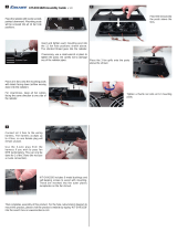
5. Use a panel puller to remove the 12 body pins and a
pair of side cutters to clip the 7 plastic rivets that retain
each of the inner fender well liners and remove them.
6. Use a 10mm socket to remove the bolt at the top of
each front wheel well.
7. Use a 10mm deep socket to remove the nut inside
each of the front wheel wells.

©2016 Edelbrock LLC
Part #1530, 1531, 1532, 1533, 1536 & 1537
Brochure #63-1530
Rev. 8/2/16 - QT
Edelbrock Hemi Supercharger System
2005 - 2010 Dodge/Chrysler Vehicles
Installation Instructions
Page 11
8. Use a 7mm socket and a panel puller to remove the 10
bolts and 3 pins retaining the splash shield to the front lip.
9. Use a 10mm socket to remove the 4 additional bolts
retaining the plastic splash shield.
10. Lift the plastic radiator shroud covers from underneath
the hood latch and put them aside.
11. Use a panel puller to remove the 4-10 (depending on
vehicle) push pins along the top of the front fascia.
12. Use a 10mm universal socket to remove the bolts at
both top corners of the front fascia.
13. Disconnect the fog lamp electrical connectors, if
necessary; otherwise just disconnect the lighting harness
connector from the main engine harness.
14. Remove front fascia and place aside.
15. Remove the radiator shrouds.
16. Squeeze the clips to detach the transmission cooler (if
equipped) from the AC condenser.
17. Use an 8mm socket to remove the 4 bolts supporting
the AC condenser then use some mechanic’s wire to
support the condenser.
18. Place a drain pan below the petcock on the passenger
side of the radiator then loosen the petcock and drain the
coolant.
19. Use a 10mm socket to remove the two bolts securing
the top of the radiator.
20. Disconnect the radiator fan harness connector.

©2016 Edelbrock LLC
Part #1530, 1531, 1532, 1533, 1536 & 1537
Brochure #63-1530
Rev. 8/2/16 - QT
Edelbrock Hemi Supercharger System
2005 - 2010 Dodge/Chrysler Vehicles
Installation Instructions
Page 12
21. Use a 13mm socket to remove the radiator hose
housing from the water pump assembly.
22. Use a 10mm socket to remove the bolt that secures
the power steering line to the top of the crossmember.
23. Vehicles equipped with a three row transmission
cooler should use a 10mm socket to remove the bolt that
secures each horn bracket and set the horns aside.
24. Disconnect upper and lower radiator hose from the
radiator.
25. Remove lower airbox with 10mm socket to get to the
driver side bolts on the radiator saddle.
26. Use a 13mm socket to remove the four bolts supporting
the radiator saddle then lower the radiator, fans and upper
hose out of the car as a single assembly.
27. Use a 3/8” drive breaker bar to loosen the tensioner
and remove the serpentine belt. Check the belt for cracks
and replace if necessary. DO NOT discard belt as it will be
reused.
28. Use a 21mm socket and an impact gun to remove the
crankshaft pulley bolt.

©2016 Edelbrock LLC
Part #1530, 1531, 1532, 1533, 1536 & 1537
Brochure #63-1530
Rev. 8/2/16 - QT
Edelbrock Hemi Supercharger System
2005 - 2010 Dodge/Chrysler Vehicles
Installation Instructions
Page 13
29. Use a pulley puller to pull off the crankshaft damper.
Chrysler tool #8513A or equivalent should be used to
prevent damage to the end of the crankshaft.
NOTE: Some 5.7L models will require a bolt grip pulley
puller for removal. Three (3) long M8 bolts are also
required (not included) to thread into the front holes on
the damper.
30. Install the supplied drilling guide and rotate it so that
you will be able to access the sleeved hole with your drill.
Secure the guide with the stock bolt.
31. Use a piece of masking tape to mark the supplied drill
bit 1.02” from the end of the tip.
32. Drill through the guide into the crank until the tape
mark hits the guide then loosen the crank bolt. Be sure the
drill bit does not break through into the counterbore.
33. Use compressed air to clean out the hole just drilled.
CAUTION: Use extreme caution when doing this to make
sure no debris gets past the seal into the crankcase, as this
will require a great deal of disassembly to correct or could
cause severe engine damage if ignored. Spin the guide and
use the supplied reamer to center the other guide hole on
the drilled hole, then tighten down the crank bolt to secure
the guide. Use the reamer to ream the hole.
34. Remove the stock crank bolt and the drill guide then
clean out the hole in the crank with compressed air.
35. Apply a dab of green Loctite to the supplied crank pin
and insert it into the hole in the crank. It might be necessary
to turn the engine over to prevent the pin from falling out.
36. Apply a thin layer of engine oil to the end of crankshaft,
then install the damper onto the crankshaft. Use Chrysler
tool #8512A or equivalent to fully seat damper onto
crankshaft. Use caution to avoid damaging the front crank
seal during installation, do not apply any lube to front crank
seal. The snout of crankshaft pulley and the crank seal
should be dry when installed.
37. Once the balancer is fully installed, apply silicone to
key way to prevent any oil weeping. Torque the stock
crank bolt to 129 ft-lbs.
38. Attach the supercharger pulley to the balancer then
apply red Loctite to the bolts and install them using a 1/4”
Allen socket. Torque bolts to 18 ft-lbs in a star pattern.

©2016 Edelbrock LLC
Part #1530, 1531, 1532, 1533, 1536 & 1537
Brochure #63-1530
Rev. 8/2/16 - QT
Edelbrock Hemi Supercharger System
2005 - 2010 Dodge/Chrysler Vehicles
Installation Instructions
Page 14
39. Loosen the worm clamps securing the air inlet tube
and use a 10mm socket to remove the bolt securing the
stock air box. Disconnect the engine harness from the IAT
sensor, then remove the airbox and air inlet tube.
40. Use a 15mm wrench to remove the stud at the top of
the water pump and a 13mm socket to remove the two
nearby bolts.
41. Remove the bolt that secures the idler pulley and set
the pulley aside for reuse later.
42. Remove the plastic engine covers from the valve
covers by lifting them by the ends.
43. (NOTE: 2006-2008 5.7L Vehicles Only ) Use an
8mm socket to remove the two bolts securing the EGR
tube, then pull it out of the manifold.
44. Use a 3/8” Fuel Line Removal Tool to disconnect the
fuel line from the passenger side fuel rail.
45. Pull the EVAP hose off the nipple on the solenoid.
46. Remove ETC electrical connector from throttle body.
47. Use a 8mm socket to remove the ten manifold bolts.
48. Separate the main wiring harness from the back of the
manifold.

©2016 Edelbrock LLC
Part #1530, 1531, 1532, 1533, 1536 & 1537
Brochure #63-1530
Rev. 8/2/16 - QT
Edelbrock Hemi Supercharger System
2005 - 2010 Dodge/Chrysler Vehicles
Installation Instructions
Page 15
49. Pull the manifold forward to gain access to the brake
booster hose and pull it off its nipple.
50. The intake manifold can now be removed along with
the EVAP hose disconnected from the solenoid earlier.
51. Use a soft cloth to clean the intake flange of the
cylinder heads, using caution to make sure that no debris
enters the intake ports, then apply strips of masking tape to
cover the ports.
52. Use a 10mm socket to remove the two bolts securing
each ignition coil, then pull them out. Keep the coils in
order so that they can be reinstalled in the same place.
53. Use a 5/8” spark plug socket to remove all 16 spark
plugs. Inspect and replace them, as needed, or replace
them all with the colder plugs recommended before step
1. Both stock and new plugs should be gapped to .035”.
Apply a dab of anti-seize to the threads of each plug and
install them.
54. Reinstall the ignition coils in the same location they
were originally and secure them with the stock bolts.
55. Install the stock serpentine belt in the stock routing
configuration, do not tension yet.
56. Install the stock idler pulley behind the supplied
tensioner bracket with the M10 countersunk bolt supplied
in Bag #2, but do not fully tighten it just yet. NOTE: 2009-
2010 models will use the smaller M8 countersunk bolt in
bag #2.
57. Use the three M8 socket cap bolts supplied in Bag #2
to secure the tensioner bracket. Install the 90mm bolt in
the top hole on the driver side and the 40mm bolt on the
passenger side, then slide the 75mm bolt into the hole on
the tensioner pad and install the supplied M6 nut on the
end of the bolt. Use a long Allen tool to tighten the bolts,
including the countersunk one previously installed.
58. Install the supplied idler pulleys onto the tensioner
bracket using a 12mm socket, the M8 x 20mm bolts and
M8 washers supplied in Bag #2 and a dab of blue Loctite,
then torque them to 18 ft-lbs.

©2016 Edelbrock LLC
Part #1530, 1531, 1532, 1533, 1536 & 1537
Brochure #63-1530
Rev. 8/2/16 - QT
Edelbrock Hemi Supercharger System
2005 - 2010 Dodge/Chrysler Vehicles
Installation Instructions
Page 16
59. Install the supplied serpentine belt tensioner onto the
tensioner bracket using a 15mm socket, the M10 x 45mm
bolt supplied in Bag #2 and a dab of blue Loctite, then
torque it to 37 ft-lbs. Once the tensioner has been secured,
complete the tensioning of the stock serpentine belt.
60. Loosely install the nose support blocks at the top of the
tensioner bracket using the M6 x 20mm socket cap bolts
supplied in Bag #2.
61. Use a 5/16” Fuel Line Removal Tool to detach the fuel
input line from the factory hard line near the firewall on the
passenger side then attach the supplied fuel input line to
the hard line.
62. For 6.1L engines, remove the gaskets from the
flange of the stock intake manifold then clip off the small
plastic locator pins. For ‘06-’08 5.7L engines, remove the
O-ring seals from the flange of the stock intake manifold
and trim the tabs, then install them in the grooves on the
supercharger flange. Inspect gaskets for damage prior
to installation and replace them, if necessary. ‘09+ 5.7L
engines will use the supplied gaskets.
63. Remove the tape covering the intake ports of the
heads and inspect the area to ensure that no residue
remains on the flanges. 6.1L and ‘09+ 5.7L applications
should lay the gaskets flat on the intake flanges.
64. With the help of an assistant or a cherry picker, lift the
supercharger into the engine bay. Use the intake bolt holes
and injector bores to achieve the best alignment possible
between the engine and the supercharger.
65. Use a 10mm universal socket to install the eight intake
manifold bolts following the sequence shown below, then
torque them to 9 ft-lbs in the same order.
4 1 86
32 57
Front

©2016 Edelbrock LLC
Part #1530, 1531, 1532, 1533, 1536 & 1537
Brochure #63-1530
Rev. 8/2/16 - QT
Edelbrock Hemi Supercharger System
2005 - 2010 Dodge/Chrysler Vehicles
Installation Instructions
Page 17
66. Apply a dab of lube to the O-rings of the supplied fuel
rail fittings. Install the two straight fittings on the rear
provisions of the rails. Install the 180° fitting on the front
provision of the passenger side rail and the plug in the front
provision of the driver side rail.
67. Attach the supplied fuel rail crossover line to the
straight fitting on the passenger side fuel rail.
68. Apply a dab of lube to the upper O-rings of the
supplied fuel injectors, then install them in the fuel rails
with the connectors oriented away from the supercharger.
69. Apply a dab of lube to the lower O-rings of the fuel
injectors, then install the fuel rails by sliding the injectors
down into the manifold provisions and applying pressure
until the mounting holes in the rails line up with the
manifold. Connect the input line to the 180° fitting on the
front of the passenger side rail then route the crossover
hose around the fuel input line and behind the manifold as
you install the passenger side rail and connect it to the
driver side rail.
70. Use a 10mm socket to install the four M6 x 40mm
bolts supplied in Bag #1 through the rails to the manifold,
then remove the oil fill cap from the stock manifold and
install it on the driver side of the supercharger.
71. Push the nose support blocks tight against the shaft
housing and tighten the bolts with a 5mm Allen socket.
72. Attach the supplied brake booster hose to the fitting on
the driver side of the air inlet snout, route it along the driver
side valve cover and attach it to the brake booster.
73. Install the supplied EVAP hose between the solenoid
and the smaller, rear fitting on the passenger side of the air
inlet. The end of the hose with a quick disconnect fitting
attaches to the air inlet.
PCV
EVAP
74. If you have a 6.1L engine, remove the PCV valve from
the front of the stock manifold, below the throttle body
flange; 5.7L applications will use the supplied PCV valve.
Thread the PCV valve into the block extending from the
passenger side runner of the supercharger then install the
supplied passenger side PCV hose between the PCV valve
and the larger, front fitting on the passenger side of the air
inlet.

©2016 Edelbrock LLC
Part #1530, 1531, 1532, 1533, 1536 & 1537
Brochure #63-1530
Rev. 8/2/16 - QT
Edelbrock Hemi Supercharger System
2005 - 2010 Dodge/Chrysler Vehicles
Installation Instructions
Page 18
75. Install the supercharger drive belt according to the
diagram.
76. Depress the lock tabs and remove the plastic bumper
cover, if equipped.
77. Use a 13mm socket to remove the two outboard,
passenger side bumper bolts and replace them with the M8
x 30mm bolts supplied in Bag #3.
78. Detach the connector from the frame, if equipped.
79. Loosely assemble the supplied metal strap to the
water pump bracket using one of the M8 x 30mm bolts
supplied in Bag #3, then mount the water pump bracket on
the two new bumper bolts and secure it with the two M8
nuts supplied in Bag #3.
80. With the strap as loose as possible, remove the paper
from the foam adhesive and slide the pump into place,
oriented so that the inlet will be pointing down and the
outlet pointing toward the radiator. Leave a gap between
the outlet and the frame to allow the hose to be installed,
then tighten the strap bolt.

©2016 Edelbrock LLC
Part #1530, 1531, 1532, 1533, 1536 & 1537
Brochure #63-1530
Rev. 8/2/16 - QT
Edelbrock Hemi Supercharger System
2005 - 2010 Dodge/Chrysler Vehicles
Installation Instructions
Page 19
81. Vehicles equipped with a transmission cooler will need
to pull off the retaining discs in order to relocate the cooler
support clips to the top row of the condenser. Vehicles
equipped with the three row cooler will need to drain the
power steering reservoir and install the supplied hose
extension on the passenger side using the supplied coupler
and clamps.
82. Vehicles equipped with the three row cooler should
now reinstall the horns using the supplied brackets.
83. (NOTE: For Vehicles Equipped w/ Dual Fans,
Follow Steps 83-87. For Vehicles Equipped w/ Single
Fans, Skip Proceed to Step 88. ) Use an 8mm socket to
remove the two bolts securing the radiator fan assembly to
the radiator.
84. Disconnect the passenger side radiator fan
connector.
85. Use a 10mm socket to remove the three bolts securing
the passenger side radiator fan motor housing.
86. Rotate the passenger side radiator fan motor housing
one bolt hole clockwise so that the electrical connector will
face upward, then trim the fan shroud to clear the new
harness connector location. Use the stock bolts to secure
the fan in its new orientation. Route the wire extending
from the connector so that it will not contact the fan blades
or serpentine belt when reinstalled.
87. Use the stock bolts to reattach the radiator fan
assembly to the radiator then raise the radiator and cradle
assembly back into the engine bay and secure it with the
stock bolts. Pull the radiator and cradle as far forward as
the bolts will allow before tightening them.
/