Page is loading ...

DP/N: 4CM020-010 - v2.3, 05/19/21
Dodge
Challenger 6.4L
Supercharger System
Installation Instructions
1650 Pacific Avenue, Channel Islands, CA 93033-9901 • Phone (805) 247-0226
Fax: (805) 247-0669 • www.vortechsuperchargers.com • M-F 7:00 AM - 3:30 PM (PST)
ENGINEERING, INC
2015-2019 Model Year
50 State Smog Legal Per CARB EO# D-213-39
®

P/N: 4CM020-010 v2.3, 05/19/21
©2021 Vortech Engineering, Inc.
All Rights Reserved, Intl. Corp. Secured ii
FOREWORD
Take note of the following before proceeding:
1. Proper installation of this supercharger kit requires general automotive mechanic knowl-
edge and experience. Please browse through each step of this instruction manual prior
to beginning the installation to determine if you should refer the job to a professional
installer/technician. Please contact your dealer or Vortech Engineering for possible
installers in your area.
2. This product was designed for use on stock (un-modified, OEM) vehicles. The PCM
(computer), engine, transmission, drive axle ratios and tire O.D. must be stock. If the
vehicle or engine has been modified in any way, check with Vortech prior to installation
and use of this product.
3. Use only premium grade fuel with a minimum of 91 octane (R+M/2).
4. Always listen for any sign of detonation (knocking/pinging) and discontinue hard use
(no boost) until problem is resolved.
5. Vortech is not responsible for any clutch, transmission, drive-line or engine damage.
Exclusions from Vortech warranty coverage considerations include, but not limited to:
1. Neglect, abuse, lack of maintenance, abnormal operation or improper installation.
2. Continued operation with an impaired vehicle or sub-system.
3. The combined use of Vortech components with other modifications such as, but not limit-
ed to, exhaust headers, aftermarket camshafts, nitrous oxide, third party PCM program-
ming or other such changes.
©2021 VORTECH ENGINEERING, INC
All rights reserved. No part of this publication may be reproduced, transmitted, transcribed, or translated
into another language in any form, by any means without written permission of Vortech Engineering, Inc.
This manual provides information on the installation, maintenance and service of the
Vortech supercharger kit expressly designed for this vehicle. All information, illustra-
tions and specifications contained herein are based on the latest product information
available at the time of this publication. Changes to the manual may be made at any time
without notice. Contact Vortech Engineering for any additional information regarding this kit
and any of these modifications at (805) 247-0226 7:00am-3:30pm PST.
STOP

P/N: 4CM020-010 v2.3, 05/19/21
©2021 Vortech Engineering, Inc.
All Rights Reserved, Intl. Corp. Secured
iii
TABLE OF CONTENTS
FOREWORD ....................................................................ii
TABLE OF CONTENTS............................................................iii
IMPORTANT NOTES..............................................................iv
TOOL & SUPPLY REQUIREMENTS..................................................v
PARTS LIST.....................................................................vi
1. ECU REMOVAL .............................................................1
2. BASIC COMPONENT REMOVAL ...............................................5
3. HARMONIC DAMPER DOWEL PIN INSTALLATION ...............................15
4. FAN SHROUD & LOWER RADIATOR MOUNT MODIFICATION ......................19
5. ENGINE COOLING SYSTEM MODIFICATION....................................23
6. S/C MOUNTING BRACKET ASSEMBLY INSTALLATION ...........................27
7. DISCHARGE ASSEMBLY & HEAT EXCHANGER INSTALLATION ....................31
8. AIR INLET ASSEMBLY, BYPASS VALVE SIGNAL HOSE & S/C INSTALLATION .........43
9. AIR-TO-WATER COOLING SYSTEM INSTALLATION ..............................47
10. RADIATOR FAN SHROUD MODIFICATION & INSTALLATION .......................57
11. FUEL INJECTOR & MAP SENSOR REPLACEMENT (COMPLETE KIT ONLY) ..........59
12. FUEL PUMP BOOSTER INSTALLATION (COMPLETE KIT ONLY) ....................63
13. MISC. REASSEMBLY .......................................................65
14. PROGRAMMING CABLE INSTALLATION (2018-2019 VEHICLES ONLY) .............. 67
15. REFLASH COMPUTER (COMPLETE KIT ONLY) .................................69
16. FINAL CHECK .............................................................71
APPENDIX A - DIAGRAM, ASSEMBLY, SUPERCHARGER MOUNTING BRACKET ..........72
APPENDIX B - DIAGRAM, BELT ROUTING ..........................................73
APPENDIX C - DIAGRAM, AIR-TO-WATER COOLING SYSTEM.......................... 74
APPENDIX D - DIAGRAM, DISCHARGE TUBE ASSEMBLY .............................75

P/N: 4CM020-010 v2.3, 05/19/21
©2021 Vortech Engineering, Inc.
All Rights Reserved, Intl. Corp. Secured iv
NOTICE
This product is protected by state common law, copyright and/or patent.
All legal rights therein are reserved. The design, layout, dimensions,
geometry, and engineering features shown in this product are the exclu-
sive property of Vortech Engineering, Inc. This product may not be cop-
ied or duplicated in whole or part, abstractly or fundamentally, intention-
ally or fortuitously, nor shall any design, dimension, or other information
be incorporated into any product or apparatus without prior written con-
sent of Vortech Engineering, Inc.

P/N: 4CM020-010 v2.3, 05/19/21
©2021 Vortech Engineering, Inc.
All Rights Reserved, Intl. Corp. Secured
v
Before beginning this installation, please read through this entire instruction booklet and the Street
Supercharger System Owner’s Manual which includes the Limited Warranty Program, the Warranty
Registration form and return envelope.
Vortech supercharger systems are performance improving devices. In most cases, increases in
torque of 30-35% and horsepower between 35-45% can be expected with the boost levels specified
by Vortech Engineering. This product is intended for use on healthy, well maintained engines.
Installation on a worn-out or damaged engine is not recommended and may result in failure of the
engine as well as the supercharger. Vortech Engineering is not responsible for engine damage.
Installation on new vehicles will not harm or adversely affect the break-in period so long as factory
break-in procedures are followed.
For best performance and continued durability, please take note of the following key points:
1. Use only premium grade fuel 91 octane or higher (R+M/2).
2. The engine must have stock compression ratio.
3. If the engine has been modified in any way, check with Vortech prior to using this product.
4. Always listen for any sign of detonation (pinging) and discontinue hard use (no boost) until
problem is resolved.
5. Oil Fed Units - Perform an oil and filter change upon completion of this installation and
prior to test driving your vehicle. Thereafter, always use a high grade SF rated engine oil or
a high quality synthetic, and change the oil and filter at least every 3,000 miles. Never
attempt to extend the oil change interval beyond 3,000 miles, regardless of oil manufactur-
er’s claims as potential damage to the supercharger may result.
6. Before beginning installation, replace all spark plugs that are older than 1-year or 15,000
miles with original heat range plugs as specified by the manufacturer and reset timing to
factory specifications (follow the procedures indicated within the factory repair manual and/
or as indicated on the factory underhood emissions tag). Do not use platinum spark plugs
unless they are original equipment. Change spark plugs every 15,000 miles.
TOOL & SUPPLY REQUIREMENTS
• 1/4" drive & 3/8" drive ratchet and drive set: SAE & metric
• 1/4" drive & 3/8" drive ratchet extensions
• Open end wrenches: SAE & metric
• Torque wrench
• Screwdriver set
• Hose cutters
• Drill motor & 1/4" drill bit
• Wire strippers & crimpers
• Utility knife
• Blue and red threadlocker
• Pipe sealant
If it has been 15,000 miles or more since your vehicle’s last spark plug change, then you will
also need:
• Spark plug socket
• NEW spark plugs
2015-2019 Dodge Challenger 6.4L
Installation Instructions
Congratulations on selecting the best performing and best backed automotive
supercharger available today... the VORTECH® supercharger!

P/N: 4CM020-010 v2.3, 05/19/21
©2021 Vortech Engineering, Inc.
All Rights Reserved, Intl. Corp. Secured vi
PART NO. DESCRIPTION QTY. PART NUMBER DESCRIPTION QTY.
IMPORTANT: Before beginning installation, verify that all parts are included in the kit. Report any shortages or dam-
aged parts immediately.
PARTS LIST
008110 SMALL SILVER DIE CUT DECAL 2
008130 LICENSE PLATE FRAME, VORTECH 1
008447 1 YR S/C STRT INFO PKG ASY VORT 1
009035 S/C LUBE, BOTTLED, 3-PACK 1
2A046-988 BELT, K060988, GATES 1
2F329-170 V3 S/C ASY, 15-19 HEMI 1
4CL110-110 ASY, DAMPER PIN, HEMI 1
4GR010-110 GUIDE, DWL PIN IST, C5 1
7C014-095 M14-1.5 X 95 MM SHCS,PLATED 1
7U250-019 DOWEL PIN,1/4D X 1/2L 1
7U250-026 DRILL BUSHING, 1/4ID,.375OD 1
4CM020-010 INSTR MAN, 15-19 CHAL 6.4L 1
4CM110-044 MNTG BRKT ASY, 15-19 HEMI 1
2A017-016 PILOT, 6203/5 BRG, M10 3/8 SCREW 1
2A040-021 RETAINER, PULLEY, FLATHD 1
2A040-051 PLY RETAINER, TAMPER PRF CAP 1
2A040-061 RETAINER CUP, VORT S/C PLY 1
2A042-080 BELT, GATES 20MM, 80T COG 1
2D170-171 ASSY, JACKSHAFT, SHORT 1
4CL116-350 IDLR ASSY, 3.5" DIA 20MM COG, SRT8 1
4CM010-020 S/C MNTG PLT A, 15-17 HEMI CAR 1
4CM010-044 S/C MNTG PLT B, 15-17 HEMI CAR 1
4CM010-050 PULLEY GUARD, 15-17 HEMI CAR 1
4CM036-360 S/C PULLEY 3.60" 6 GROOVE 1
4CM100-001 HARDWARE ASSY, S/C MNTG BRKT 1
4CM100-002 SPACER ASSY, S/C MNTG BRKT 1
4FH016-150 IDLER PLY, SMOOTH 6RIB 3" FLANGD 1
4GR032-032 PLY, JACKSHAFT, C5, 20MM, 32T 1
4CM112-030 AIR INLET ASSY, 15-19 HEMI 1
7P500-009 1/2" X 90 HOSE BARB UNION 1
7P750-502 REDUCER, 3/4" TO 1/2" COUPLER 1
7U030-036 1/2" OIL DRAIN HOSE 2.5FT
8H040-240 AIR FILTER, 15-17 HEMI CAR 1
4CM155-020 SPRT ITMS, CAC SYS, 15-19 CHAL 1
4CM010-060 BRKT, RAD SHROUD, 1.00", CHALL 1
4CM010-070 BRKT, RAD SHROUD, .750", CHALL 2
4CM011-012 BRKT, HEAT EXCHANGER, P. SIDE 1
4CM011-013 BRKT, HEAT EXCHANGER, D. SIDE 1
4CM011-014 BRKT, CAC RESERVOIR, 15-17 HEMI 1
4CM011-015 BRKT, CAC, D. SIDE, 15-17 HEMI 1
4CM011-016 BRKT, CAC, P. SIDE, 15-17 CHALL 1
4CM011-017 BRKT, CAC, TOP SIDE, 15-17 CHALL 1
4CM011-018 HORN BRKT, 15-17 HEMI CAR 1
4CM055-020 RESERVOIR, CAC, 15-17 HEMI 1
5W001-082 SLEEVE, FLEX BRAID .75" NOM. 8FT
7A250-050 1/4-20 X .50 SHCS GR8 ZINC PLTD 8
7A250-051 1/4-20 X .50 HHCS GR5 ZINC PLTD 1
7A250-075 1/4-20 X .75 SHCS PLTD 2
7A250-500 1/4-20 X 5 SHCS 4
7C060-011 M6 X 1.0 X 10 HXHD CL8.8 PLT 1
7C080-012 M8 X 1.25 X 12MM LOW SHCS 1
7F006-093 NUT, M6 X 1.0, NYLOCK, PLATED 2
7F250-021 1/4-20 NYLOCK NUT ZINC PLATED 4
7J250-001 1/4 WASHER, SAE, PLTD 12
7J312-000 5/16 FLAT WASHER-SAE 1
7P375-075 3/4" HOSE BARB UNION, BRASS 1
7P500-035 FITTING, 1/2 NPT X 3/4 BARB X 45 1
7P500-078 1/2NPT X 3/4 HOSE FIT STRT 1
7P750-502 REDUCER, 3/4" TO 1/2" COUPLER 1
7P750-503 3/4-1/2 REDUCER BARB 90 1
7R001-006 #6 STNLS HOSE CLAMP, NARROW 4
7R002-010 #10 SAE TYPE F SS HOSE CLAMP 8
7R004-007 STEPLESS CLAMP, 28.6 2
7T100-281 9/32" X 6" LENGTH EXTENDED DRILL 1
7U030-065 HOSE, 3/4 X 90 ELBOW, SHORT 1
7U038-000 3/4" HEATER HOSE 1.5FT
7U038-000 3/4" HEATER HOSE 4FT
7U038-012 HOSE, 3/4 DIA 90 , 4" X 12" LEGS 1
7U038-150 HOSE, 3/4 D X 150 MOLDED HOSE 2
7U041-000 1/2" HEATER HOSE 2.5FT
7U100-027 RIVET, PLASTIC, HEMI BMPR CVR 6
7U100-055 TIE WRAP, 7.5" NYLON 10
7U100-102 BUMPER, RUBBER, 1/4" HOLE, 1/8" 3
7U133-500 1/2 X 90 MOLDED RUBBER HOSE 1
4CM212-010 DISCH ASY, 15-19 CHAL 6.4L 1
2A017-094 SPACER, .380L, .313ID, .60OD 2
4CM012-010 DISCH TUBE A, 15-17 CHALL 1
4CM012-030 DISCH SLEEVE C, 15-17 HEMI 1
4CM012-050 DISCH SLEEVE E, 15-17 HEMI 6.4L 1
4CM112-020 ASY, DISCH TUBE B, 15-17 CHALL 1
4CM112-040 ASY, DISCH TUBE D, 15-17 HEMI 1
7A250-074 1/4-20 X .75 HHCS PLTD 2
7C060-030 M6 X 1.0 X 30MM, FLG HD, PLATED 2
7F250-021 1/4-20 NYLOCK NUT ZINC PLATED 2
7J250-001 1/4 WASHER, SAE, PLTD 4
7P375-250 3/8 X 3/8 X 1/4 MALE BARB TEE 1
7PS300-275 REDUCER, BLK 3.0- 2.75 1
7PS300-300 SLEEVE, BLACK, 3.00D X 3.00 1
7PS300-301 BUMP HOSE, 3.00D X 3.00L 1
7R002-044 #44 SAE TYPE F SS HOSE CLAMP 2
7R002-048 #48 SAE TYPE F SS HOSE CLAMP 7
7R002-056 #56 SAE TYPE F SS HOSE CLAMP 1
7R004-007 STEPLESS CLAMP, 28.6 1
7U030-218 7/32 VAC HOSE, BUNA-N 5
5A002-071 MAP SENSOR, 3-BAR, SRT-4 1
5A003-160 PROG, LIVERNOIS, MYCAL TOUCH 1
5A102-040 ASY, VOLT BST, PNP, 15-19 HEMI 1
8D204-113 ASSY, BILLET BYPASS VALVE 1
8F060-006 FUEL INJECTOR, HELLCAT 8
8N006-026 HEAT EXCHANGER, CAC SYS 1
8N107-200 ASY, W/P MNTG, 15-19 HEMI 1
5W001-141 HARNESS, AUX W/P, 15-17 HEMI CAR 1
7A250-075 1/4-20 X .75 SHCS PLTD 1
7F250-021 1/4-20 NYLOCK NUT ZINC PLATED 1
7R003-029 ADEL CLAMP, 1-5/8" ID 1
8F001-405 BOSCH AUX WATER PUMP 1
8N201-400 ASY, CAC, SAT, 15-19 HEMI 1
2015-2019 Dodge Challeger 6.4L
Complete Kit Part No. 4CM218-010L
®

P/N: 4CM020-010 v2.3, 05/19/21
©2021 Vortech Engineering, Inc.
All Rights Reserved, Intl. Corp. Secured
vii
PART NO. DESCRIPTION QTY. PART NUMBER DESCRIPTION QTY.
IMPORTANT: Before beginning installation, verify that all parts are included in the kit. Report any shortages or dam-
aged parts immediately.
PARTS LIST
2015-2019 Dodge Challenger 6.4L
Tuner Kit Part No. 4CM218-110L
®
008110 SMALL SILVER DIE CUT DECAL 2
008130 LICENSE PLATE FRAME, VORTECH 1
008447 1 YR S/C STRT INFO PKG ASY VORT 1
009035 S/C LUBE, BOTTLED, 3-PACK 1
2A046-988 BELT, K060988, GATES 1
2F329-170 V3 S/C ASY, 15-19 HEMI 1
4CL110-110 ASY, DAMPER PIN, HEMI 1
4GR010-110 GUIDE, DWL PIN IST, C5 1
7C014-095 M14-1.5 X 95 MM SHCS,PLATED 1
7U250-019 DOWEL PIN,1/4D X 1/2L 1
7U250-026 DRILL BUSHING, 1/4ID,.375OD 1
4CM020-010 INSTR MAN, 15-19 CHALL 6.4L 1
4CM110-044 MNTG BRKT ASY, 15-19 HEMI 1
2A017-016 PILOT, 6203/5 BRG, M10 3/8 SCREW 1
2A040-021 RETAINER, PULLEY, FLATHD 1
2A040-051 PLY RETAINER, TAMPER PRF CAP 1
2A040-061 RETAINER CUP, VORT S/C PLY 1
2A042-080 BELT, GATES 20MM, 80T COG 1
2D170-171 ASSY, JACKSHAFT, SHORT 1
4CL116-350 IDLR ASSY, 3.5" DIA 20MM COG, SRT8 1
4CM010-020 S/C MNTG PLT A, 15-17 HEMI CAR 1
4CM010-044 S/C MNTG PLT B, 15-17 HEMI CAR 1
4CM010-050 PULLEY GUARD, 15-17 HEMI CAR 1
4CM036-360 S/C PULLEY 3.60" 6 GROOVE 1
4CM100-001 HARDWARE ASSY, S/C MNTG BRKT 1
4CM100-002 SPACER ASSY, S/C MNTG BRKT 1
4FH016-150 IDLER PLY, SMOOTH 6RIB 3" FLANGD 1
4GR032-032 PLY, JACKSHAFT, C5, 20MM, 32T 1
4CM112-030 AIR INLET ASSY, 15-19 HEMI 1
7P500-009 1/2" X 90 HOSE BARB UNION 1
7P750-502 REDUCER, 3/4" TO 1/2" COUPLER 1
7U030-036 1/2" OIL DRAIN HOSE 2.5FT
8H040-240 AIR FILTER, 15-17 HEMI CAR 1
4CM155-020 SPRT ITMS, CAC SYS, 15-19 CHAL 1
4CM010-060 BRKT, RAD SHROUD, 1.00", CHALL 1
4CM010-070 BRKT, RAD SHROUD, .750", CHALL 2
4CM011-012 BRKT, HEAT EXCHANGER, P. SIDE 1
4CM011-013 BRKT, HEAT EXCHANGER, D. SIDE 1
4CM011-014 BRKT, CAC RESERVOIR, 15-17 HEMI 1
4CM011-015 BRKT, CAC, D. SIDE, 15-17 HEMI 1
4CM011-016 BRKT, CAC, P. SIDE, 15-17 CHALL 1
4CM011-017 BRKT, CAC, TOP SIDE, 15-17 CHALL 1
4CM011-018 HORN BRKT, 15-17 HEMI CAR 1
4CM055-020 RESERVOIR, CAC, 15-17 HEMI 1
5W001-082 SLEEVE, FLEX BRAID .75" NOM. 8FT
7A250-050 1/4-20 X .50 SHCS GR8 ZINC PLTD 8
7A250-051 1/4-20 X .50 HHCS GR5 ZINC PLTD 1
7A250-075 1/4-20 X .75 SHCS PLTD 2
7A250-500 1/4-20 X 5 SHCS 4
7C060-011 M6 X 1.0 X 10 HXHD CL8.8 PLT 1
7C080-012 M8 X 1.25 X 12MM LOW SHCS 1
7F006-093 NUT, M6 X 1.0, NYLOCK, PLATED 2
7F250-021 1/4-20 NYLOCK NUT ZINC PLATED 4
7J250-001 1/4 WASHER, SAE, PLTD 12
7J312-000 5/16 FLAT WASHER-SAE 1
7P375-075 3/4" HOSE BARB UNION, BRASS 1
7P500-035 FITTING, 1/2 NPT X 3/4 BARB X 45 1
7P500-078 1/2NPT X 3/4 HOSE FIT STRT 1
7P750-502 REDUCER, 3/4" TO 1/2" COUPLER 1
7P750-503 3/4-1/2 REDUCER BARB 90 1
7R001-006 #6 STNLS HOSE CLAMP, NARROW 4
7R002-010 #10 SAE TYPE F SS HOSE CLAMP 8
7R004-007 STEPLESS CLAMP, 28.6 2
7T100-281 9/32" X 6" LENGTH EXTENDED DRILL 1
7U030-065 HOSE, 3/4 X 90 ELBOW, SHORT 1
7U038-000 3/4" HEATER HOSE 1.5FT
7U038-000 3/4" HEATER HOSE 4FT
7U038-012 HOSE, 3/4 DIA 90 , 4" X 12" LEGS 1
7U038-150 HOSE, 3/4 D X 150 MOLDED HOSE 2
7U041-000 1/2" HEATER HOSE 2.5FT
7U100-027 RIVET, PLASTIC, HEMI BMPR CVR 6
7U100-055 TIE WRAP, 7.5" NYLON 10
7U100-102 BUMPER, RUBBER, 1/4" HOLE, 1/8" 3
7U133-500 1/2 X 90 MOLDED RUBBER HOSE 1
4CM212-010 DISCH ASY, 15-19 CHAL 6.4L 1
2A017-094 SPACER, .380L, .313ID, .60OD 2
4CM012-010 DISCH TUBE A, 15-17 CHALL 1
4CM012-030 DISCH SLEEVE C, 15-17 HEMI 1
4CM012-050 DISCH SLEEVE E, 15-17 HEMI 6.4L 1
4CM112-020 ASY, DISCH TUBE B, 15-17 CHALL 1
4CM112-040 ASY, DISCH TUBE D, 15-17 HEMI 1
7A250-074 1/4-20 X .75 HHCS PLTD 2
7C060-030 M6 X 1.0 X 30MM, FLG HD, PLATED 2
7F250-021 1/4-20 NYLOCK NUT ZINC PLATED 2
7J250-001 1/4 WASHER, SAE, PLTD 4
7P375-250 3/8 X 3/8 X 1/4 MALE BARB TEE 1
7PS300-275 REDUCER, BLK 3.0- 2.75 1
7PS300-300 SLEEVE, BLACK, 3.00D X 3.00 1
7PS300-301 BUMP HOSE, 3.00D X 3.00L 1
7R002-044 #44 SAE TYPE F SS HOSE CLAMP 2
7R002-048 #48 SAE TYPE F SS HOSE CLAMP 7
7R002-056 #56 SAE TYPE F SS HOSE CLAMP 1
7R004-007 STEPLESS CLAMP, 28.6 1
7U030-218 7/32 VAC HOSE, BUNA-N 5
8D204-113 ASSY, BILLET BYPASS VALVE 1
8N006-026 HEAT EXCHANGER, CAC SYS 1
8N107-200 ASY, W/P MNTG, 15-19 HEMI 1
5W001-141 HARNESS, AUX W/P, 15-17 HEMI CAR 1
7A250-075 1/4-20 X .75 SHCS PLTD 1
7F250-021 1/4-20 NYLOCK NUT ZINC PLATED 1
7R003-029 ADEL CLAMP, 1-5/8" ID 1
8F001-405 BOSCH AUX WATER PUMP 1
8N201-400 ASY, CAC, SAT, 15-19 HEMI 1

P/N: 4CM020-010 v2.3, 05/19/21
©2021 Vortech Engineering, Inc.
All Rights Reserved, Intl. Corp. Secured viii
!!BEFORE YOU BEGIN!!
STOP
Prior to removing any parts from your vehicle, we HIGHLY recommend calling
your local Dodge dealership and verifying that all outstanding recalls have been
adressed and completed, as some recalls require the ECU to be reflashed with
an updated OEM calibration. You can also visit www.mopar.com to get the
latest recall information and to schedule a service appointment.

P/N: 4CM020-010 v2.3, 05/19/21
©2021 Vortech Engineering, Inc.
All Rights Reserved, Intl. Corp. Secured
ix
In order to be able to load the Vortech tune your vehicle, the ECU will need to
be sent to Livernois Motorsports for it to be unlocked. We HIGHLY recommend
sending the ECU to be unlocked BEFORE you begin the installation of your
supercharger kit, as it may take some time for your ECU to be returned to you.
While you wait for your ECU to return, you may begin the installation of your
supercharger kit.
An ECU Unlock Voucher, shipping box, and prepaid shipping label is included
with Complete Kits ONLY. Additionally, 2018-2019 model-year vehicles require
a Programming Cable from Livernois Motorsports in order to properly load the
Vortech tune to your vehicle. The Programming Cable will be included when
your ECU is returned to you.
NOTICE: TUNER KITS - You are responsible for purchasing the ECU unlock service and
Programming Cable (2018-2019 model-year vehicles) directly from Livernois Motorsports.
Purchasing these parts from Livernois Motorsports DOES NOT entitle you the Vortech tune, as the
tune is provided ONLY to customers who have purchased a Complete Kit and have a valid ECU
Unlock Voucher, which is NOT sold separately.
!!BEFORE YOU BEGIN!!
STOP

P/N: 4CM020-010 v2.3, 05/19/21
©2021 Vortech Engineering, Inc.
All Rights Reserved, Intl. Corp. Secured x
This page was left intentionally blank.

P/N: 4CM020-010 v2.3, 05/19/21
©2021 Vortech Engineering, Inc.
All Rights Reserved, Intl. Corp. Secured
1
1. ECU REMOVAL
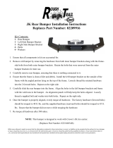
B. There are six plastic fasteners that secure the
windshield cowl to the cross bar. Using a panel
removal tool, remove the six plastic fasteners
and set them aside.
Fig. 1-b: Remove plastic fasteners
C. On the driver side of the engine compartment,
near the bottom of the windshield cowl, are
two screws that secure the cross bar. Using a
13mm socket, remove the two screws and set
them aside.
Fig. 1-c: Remove cross bar screws
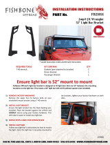
A. Open the trunk and lift the carpet. Remove the
positive battery terminal cover from the battery,
then proceed to unplug both battery leads.
CROSS BAR
SCREWS
Fig. 1-a: Unplug battery
POSITIVE
BATTERY
TERMINAL
COVER
POSITIVE
BATTERY
TERMINAL
NEGATIVE
BATTERY
TERMINAL

P/N: 4CM020-010 v2.3, 05/19/21
©2021 Vortech Engineering, Inc.
All Rights Reserved, Intl. Corp. Secured 2
1. ECU REMOVAL
E. There are two nuts securing the ECU to its
mounting bracket. Using a 10mm wrench,
remove the ECU nuts and set them aside. You
will notice that the ECU mounting bracket is
attached to the cross bar. Using a 13mm
socket, remove the two screws securing the
cross bar to the vehicle, then proceed to
remove the ECU mounting bracket and set it
aside, but leave the ECU in the vehicle.
F. If you look on the underside of the cross bar,
you will notice that the windshield wiper motor
is mounted to it using a rubber mount. Now that
the cross bar is loose, proceed to remove the
cross bar from the vehicle, making sure to
remove the windshield wiper motor mount from
the underside of the cross bar.
Fig. 1-e: Remove ECU nuts and remove cross
bar screws
Fig. 1-f: Windshield wiper motor mount
ECU NUTS
CROSS BAR
SCREWS
WIPER
MOTOR
MOUNT
RUBBER
MOUNT WIPER
MOTOR
D. On the passenger side of the engine
compartment near the windshield cowl is the
ECU cover. Using a panel removal tool, remove
the two plastic fasteners securing the ECU
cover. Set the ECU cover and two plastic
fasteners aside.
Fig. 1-d: Remove two plastic fasteners

P/N: 4CM020-010 v2.3, 05/19/21
©2021 Vortech Engineering, Inc.
All Rights Reserved, Intl. Corp. Secured
3
H. Now that the cross bar is removed, proceed to
disconnect both ECU connectors. Start by
pressing down on the lever retaining tab, then
lifting up on the lever. This applies to both
connectors. Once both connectors are
disengaged, proceed to remove the ECU from
the vehicle.
Fig. 1-h: Disconnect ECU
1. ECU REMOVAL
NOTE: In order to be able to tune the vehicle,
the ECU will need to be removed and
sent out to be unlocked by Livernois
Motorsports.
G. The ECU connectors snap in place using the a
lever on each connector. These connectors are
a two piece connector, so in some instances
they can easily come apart. Take extra care
when lifting each lever, otherwise the
connector will come apart as shown.
Fig. 1-g: ECU connectors
I. Remove and keep the rubber bumper from the
bottom of the ECU. Take care not to lose this
rubber bumper as the ECU uses it to rest
against the vehicle when it's installed.
Fig. 1-i:

P/N: 4CM020-010 v2.3, 05/19/21
©2021 Vortech Engineering, Inc.
All Rights Reserved, Intl. Corp. Secured 4
J. Locate the provided ECU Unlock Voucher and
fill it out with the requested information. Be sure
not to lose this document. Locate the provided
shipping box and pre-paid shipping label. Fill
out the shipping label with your return address.
Use the paper packaging material to protect the
ECU, then place it into the box. Place the ECU
Unlock Voucher in the box as well, then tape it
shut. Place the shipping label on the box, fill in
the return address, then mail the package to
Livernois Motorsports.
Fig. 1-j: ECU Unlock Voucher
NOTE: Complete kits only. Tuner kits, proceed
to Section 2.
1. ECU REMOVAL

P/N: 4CM020-010 v2.3, 05/19/21
©2021 Vortech Engineering, Inc.
All Rights Reserved, Intl. Corp. Secured
5
A. Remove the two plastic covers from the top of
the front bumper cover by pulling them apart at
the center, then set them aside.
B. Using a panel removal tool, remove the six
plastic fasteners securing the top of the
radiator shroud to the vehicle and set aside.
2. BASIC COMPONENT REMOVAL
Fig. 2-a: Remove covers
Fig. 2-b: Remove six plastic fasteners
C. Using a drill motor and an 1/8" drill bit, drill
through the center of the plastic rivets securing
the fender liner to the front bumper cover. New
plastic rivets are provided with this kit. Do this
for both sides of the vehicle.
Fig. 2-c: Drill through and remove plastic rivets
REMOVE
COVERS

P/N: 4CM020-010 v2.3, 05/19/21
©2021 Vortech Engineering, Inc.
All Rights Reserved, Intl. Corp. Secured 6
2. BASIC COMPONENT REMOVAL
E. Using a panel removal tool, remove the three
plastic fasteners securing the front bumper
cover to the vehicle and set aside. Next, using
a 10mm socket, remove the four screws
securing the engine service panel to the vehicle
and set aside.
D. On each side of the vehicle are two plastic
fasteners securing the engine service panel to
the inner fender liner. Using a panel removal
tool, remove these fasteners and set them
aside.
Fig. 2-e: Remove splash guard
Fig. 2-d: Remove two plastic fasteners
F. Located on each of the top corners of the front
bumper cover is a threaded stud that is used to
secure the front bumper cover to the fenders
using a nut. Using a 10mm socket, remove
these nuts and set aside.
Fig. 2-f: Remove two nuts

P/N: 4CM020-010 v2.3, 05/19/21
©2021 Vortech Engineering, Inc.
All Rights Reserved, Intl. Corp. Secured
7
G. There is one screw on each outer edge of the
front bumper cover, beneath the fender liner.
Pull back the fender liner and using a 10mm
socket, remove these screws and set them
aside.
H. On each side of the front bumper cover is
another threaded stud that secures the front
bumper cover to the fenders using a nut. To
gain access to this nut, we suggest pulling
back the fender liner, using a long extension, a
deep 10mm socket and ratchet to reach this
screw. Using the proper tools, remove the nut.
I. Located on the passenger side behind the
front bumper cover is the connector for the fog
lights that's mounted to a plastic bracket.
Disconnect the fog light connector. Detach the
connector from the plastic mounting bracket,
then remove the plastic mounting bracket from
the vehicle. It will not be reused.
2. BASIC COMPONENT REMOVAL
Fig. 2-i: Disconnect fog light connector
Fig. 2-h: Remove two nuts
(Bumper removed for clarity)
Fig. 2-g: Remove screw
DETACH CONNECTOR
FROM PLASTIC
MOUNTING BRACKET
REMOVE AND DISCARD
PLASTIC MOUNTING
BRACKET
STUD LOCATED
BEHIND FENDER
LINER
STUD LOCATED
NEAR TOP
CORNER

P/N: 4CM020-010 v2.3, 05/19/21
©2021 Vortech Engineering, Inc.
All Rights Reserved, Intl. Corp. Secured 8
2. BASIC COMPONENT REMOVAL
J. The corners of the front bumper cover typically
snap into place on the front fenders. In order to
release the front bumper cover from the front
fenders, you will need to pull the edges of the
front bumper cover away from the fenders with
a good amount of force, making sure you have
a good grip on the front bumper cover as to not
cause any damage. Once released, proceed to
remove the front bumper cover from the vehicle
and set aside.
K. Remove the plastic fasteners securing the
plastic bumper guard to the front bumper beam.
Remove the bumper guard and set aside.
L. Remove the ambient air temperature sensor
from the radiator shroud and set aside. It will be
relocated in a later step.
Fig. 2-j: Remove front bumper cover
Fig. 2-k: Remove plastic bumper guard
Fig. 2-l: Remove ambient air temperature
sensor
PULL EDGES
AWAY FROM
FENDERS

P/N: 4CM020-010 v2.3, 05/19/21
©2021 Vortech Engineering, Inc.
All Rights Reserved, Intl. Corp. Secured
9
2. BASIC COMPONENT REMOVAL
M. Using a panel removal tool, remove the four
plastic fasteners securing the top section of the
radiator shroud to the vehicle and set aside.
Fig. 2-m: Remove radiator shroud and
fasteners
N. Vehicles with Shaker hood: Located just
behind the weather stripping on each corner of
the shaker scoop are four nuts. Using a 10mm
socket, remove the four nuts securing the
shaker scoop to the shaker base.
Fig. 2-n: Remove shaker scoop
O. Vehicles with Shaker hood: Using a flathead
screw driver, loosen the air inlet hose clamp on
the underside of the shaker base.
Fig. 2-o: Loosen hose clamp
LOOSEN
HOSE CLAMP
REMOVE FOUR NUTS

P/N: 4CM020-010 v2.3, 05/19/21
©2021 Vortech Engineering, Inc.
All Rights Reserved, Intl. Corp. Secured 10
R. In order to make more working space when
pinning the crankshaft in a later step, it will be
necessary to remove the radiator fan assembly.
There is one screw on each side of the radiator
fan assembly. Using a 10mm socket, remove
the screws and set aside.
Fig. 2-r: Remove radiator fan assembly
2. BASIC COMPONENT REMOVAL
Q. Vehicles without Shaker hood: Using an 8mm
socket, remove the screw securing the airbox to
the vehicle. Detach the breather hose from the
airbox, disconnect the IAT sensor and loosen
the hose clamp securing the air inlet duct to the
throttle body. Remove the airbox and air inlet
duct from the vehicle as they will not be reused.
Set the breather hose aside as it will be reused
in a later step.
Fig. 2-q: Remove airbox and air inlet duct
IAT
SENSOR BREATHER
HOSE
AIRBOX
SCREW
P. Vehicles with Shaker hood: Using a 10mm
socket, remove the five fasteners securing the
shaker base to its mounting bracket on the
engine, then remove the shaker base from the
vehicle. Using an 8mm socket, remove the
screw securing the air filter enclosure to the
vehicle. Disconnect the IAT sensor, detach the
breather hose from the engine, loosen the hose
clamp securing the air inlet to the throttle body,
then remove the entire air inlet assembly from
the vehicle. It will not be reused.
Fig. 2-p: Remove shaker base
/