Page is loading ...

Edelbrock E-Force Supercharger
2015-2017 Dodge/Chrysler 5.7L and 6.4L HEMI
Part #1517, 15170, 15172, 151720
Pro Tuner Part #15171, 15174 (Reference Only)


WARNING!
The supercharger bypass valve is factory installed and adjusted intended to be vacuum oper-
ated only. DO NOT move the solenoid actuator lever by hand or adjust the stop point. Moving
the lever manually will damage the solenoid and the system will not function properly. Dam-
age to the bypass assembly from manual movement will not be covered under manufacture
warranty.


USA CUSTOMERS ONLY:
In order to properly calibrate your vehicle for this supercharger kit, the ECM must be removed from the
vehicle, packaged and shipped to Edelbrock. Your vehicle’s computer will be modified and or flashed
for supercharger kit compatibility. This kit contains a box for shipping the ECM to Edelbrock. (See ECM
removal procedures on the following pages.)
NOTE: Please email your Name, Address, phone number and email address to
[email protected] and a prepaid return label will be sent. Affix the label to the package
and drop it off at any UPS Store in your area.
The calibration process will take approximately 8-10 business days from the time your vehicles comput-
ers are received. To avoid unplanned vehicle down time, we recommend that the computers be shipped
out BEFORE beginning the supercharger installation.
INTERNATIONAL (NON-USA) CUSTOMERS PLEASE CALL EDELBROCK TECHNICAL SUPPORT
AT (800)-416-8628.
IMPORTANT CALIBRATION DETAILS

1. Locate the battery in the trunk of the vehicle.
Disconnect the negative battery terminal and isolate
the negative cable so it does not come in contact with
the battery terminal or body of the vehicle.
2. Accessing the ECM:
Dodge Challenger: Remove the two (2) push pins securing
the plastic ECM cover. Remove cover and set aside.
Dodge Charger/Chrysler 300: Using a panel puller, remove
the five (5) push pins securing the passenger side of the
plastic cowl.
3. Using a 13mm socket, remove the bolt securing the
ECM bracket to the frame.
4. Lift the ECM and disconnect the main harness
connections by releasing the locking levers.
5. Using a 10mm socket, remove the two (2) nuts
securing the mounting bracket to the ECM.
6. Remove the rubber bumper from the ECM and set
aside.
7. Fill out the provided calibration label with customer
and vehicle information and apply the label directly
to the ECM. Place the ECM in the provided box with
packing material so the ECM cannot move around in
the box. Ship ECM to Edelbrock using the provided
return shipping label.
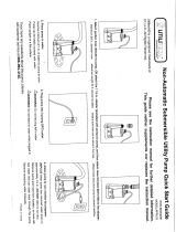
ECM Removal
The ECM is located under the hood on the passenger side of the vehicle. Follow these instructions carefully to remove,
package and ship the ECM to Edelbrock.

©2018 Edelbrock LLC
Part #1517, 15172, 15171, 15174
Brochure #63-1517
Rev. 1/30/18 - NP
Edelbrock E-Force Supercharger System
2015-17 Dodge/Chrysler 5.7L and 6.4L Hemi
Installation Instructions
Page 1
Thank you for purchasing the Edelbrock Hemi Supercharger System for various Chrysler/Dodge vehicles. The Edelbrock
E-Force Supercharger System for the 2015-2017 Hemi utilizes Eaton’s Gen VI R2650 TVS Supercharger rotors, featuring a
four lobe design with a full 170° of twist for maximum flow, minimum temperature rise, quiet operation, and the reliability
for which Eaton is known. The Edelbrock Supercharger is a complete system that maximizes efficiency and performance
by minimizing air restriction into, and out of, the supercharger. This results in maximum airflow, with minimal temperature
rise and power consumption. The supercharger housing itself is integrated into the intake manifold for a seamless design
with minimal components, eliminating the possibility of vacuum leaks between gasket surfaces. The system also utilizes
a front drive, front inlet configuration giving it the shortest, least restrictive inlet path on the market. The supercharger is
inverted, expelling the air upward. Air pressure then builds in the plenum, before being pushed through the intercooler,
oriented horizontally, above the supercharger outlet. After passing through the intercooler core twice, the air travels
through the long runners, which route straight down into the cylinder head ports. This configuration allows for a compact
package that can fit under the stock hood and cowl of the vehicles for which it was designed, without sacrificing runner
length, or intercooler area. The E-Force supercharger features a uniquely styled plenum, and includes matching side
covers. The Edelbrock supercharger provides neck snapping performance that is safe to operate on a completely stock
engine.
INTRODUCTION
TOOLS AND SUPPLIES REQUIRED
z Jack and Jack Stands OR Service Lift
z Panel Puller
z Ratchet and Socket Set including: 7mm, 8mm, 10mm
(standard, deep and swivel), 11mm, 12mm (deep),
13mm, 15mm, 18mm, 21mm (deep), 24mm
z Wrenches including: 8mm, 18mm, 27mm
z 1/2” Breaker Bar
z Flat Blade & Philips Screwdrivers
z Compressed Air
z 90° Power Drill
z Allen Wrenches including: 1/4”, 5mm, 6mm, 8mm
z Mechanic’s Wire
z Chrysler Fuel Pump Lock Ring Remover/Installer
#9340 OR Equivalent
z Side Cutters
z Dremel
z 3/8” Fuel Line Removal Tools
z Torque Wrench
z Needle Nose Pliers
z Pliers OR Hose Clamp Removal Tool
z Impact Wrench
z Blue & Green Loctite Retaining Compound or equivalent
z O-ring Lube
z Masking Tape
z Electrical Tape

©2018 Edelbrock LLC
Part #1517, 15172, 15171, 15174
Brochure #63-1517
Rev. 1/30/18 - NP
Edelbrock E-Force Supercharger System
2015-17 Dodge/Chrysler 5.7L and 6.4L Hemi
Installation Instructions
Page 2
Due to the complexity of the Edelbrock E-Force Supercharging system, it is recommended that this system only
be installed by a qualified professional with access to a service lift, pneumatic tools, and a strong familiarity
with automotive service procedures. To qualify for the optional supplemental warranty, it is necessary to have
this system installed by a Certified ASE Technician at a licensed business, Dodge/Chrysler Dealership, or an
Authorized Edelbrock Installer. Failure to do so will void and/or disqualify any and all optional supplemental
warranties offered with this system. Please contact the Edelbrock Technical Support department if you have
any questions regarding this system and/or how your installer of choice will affect any warranty coverage for
which your vehicle may qualify.
Proper installation is the responsibility of the installer. Improper installation will void all
manufacture’s standard warranties and may result in poor performance and engine or vehicle
damage.
Inspect all components for damage that may have occurred in transit before beginning
installation. If any parts are missing or damaged, contact Edelbrock Technical Support, not your
parts distributor.
Any equipment that directly modifies the fuel mixture or ignition timing of the engine can cause severe engine
damage if used in conjunction with the Edelbrock E-Force Supercharger System. This includes, but is not limited
to: OBDII programmers, MAF sensors, adapters and any other device that modifies signals to and/or from the
ECU. Aftermarket bolt-on equipment such as underdrive pulleys or air intake kits will also conflict with the
operation of the supercharger and must be removed prior to installation. Use of any of these products with the
E-Force Supercharger could result in severe engine damage.
Any previously installed aftermarket tuning equipment must be removed and the vehicle returned
to an as stock condition before installing the supercharger.
Before beginning installation, use the enclosed checklist to verify that all
components are present in the box then inspect each component for damage
that may have occurred in transit. If any parts are missing or damaged, contact
Edelbrock Technical Support (800-416-8628), not your parts distributor.
WARNING: Installation of this supercharger will result in a significant change to the
performance characteristics of your vehicle. It is highly recommended that you take some
time to familiarize yourself with the added power, and how it is delivered, in a controlled
environment. Take extra care on wet and slippery roads, as the rear tires will be more likely
to lose traction, with the added power. It is never recommended to turn off your vehicles
traction control system.
IMPORTANT WARNINGS

©2018 Edelbrock LLC
Part #1517, 15172, 15171, 15174
Brochure #63-1517
Rev. 1/30/18 - NP
Edelbrock E-Force Supercharger System
2015-17 Dodge/Chrysler 5.7L and 6.4L Hemi
Installation Instructions
Page 3
It is recommended that you check the Edelbrock Tech Center Website for any updates to this installation
manual. Please refer to the lower right hand corner to verify that you have the latest revision of this
installation manual before beginning the installation.
Tech Center: http://www.edelbrock.com/automotive_new/misc/tech_center/install/index.php
91 octane or higher gasoline is required at all times. If your vehicle
has been filled with anything less, it must be run until almost dry and
refilled with 91 or higher octane gasoline twice prior to installation.
Any failures associated with not using premium 91 octane gasoline
or higher, will be ineligible for warranty repairs.
IMPORTANT WARNINGS cont’d
Edelbrock Authorized Installer Disclaimer
Authorized installers of Edelbrock products are independent companies over which Edelbrock has no right of control. Edelbrock
LLC makes no claims regarding the abilities, expertise or competency of individual employees of any authorized installer. Each
authorized installer is an independent company and makes its own independent judgments. Edelbrock LLC specifically disclaims
any responsibility to any party including third parties for the actions, or the failure to act, of individuals, agents or a company
authorized in the installation of Edelbrock LLC products.

©2018 Edelbrock LLC
Part #1517, 15172, 15171, 15174
Brochure #63-1517
Rev. 1/30/18 - NP
Edelbrock E-Force Supercharger System
2015-17 Dodge/Chrysler 5.7L and 6.4L Hemi
Installation Instructions
Page 4
INSTALLATION HARDWARE IDENTIFICATION GUIDE
(Parts Are Not To Scale)
(1x) - Throttle Body O-Ring (Included, but not shown)
BAG #1 - MANIFOLD HARDWARE
Item P/N QTY. Description Torque Spec
1 36-4053 4 Bolt, Hex Flange, M6 x 40mm N/A
2 36-1507 4 Bolt, Hex Flange, M6 x 16mm N/A
3 36-1508 12 Bolt, Hex Flange, M6 x 30mm 8 ft/lbs
4 51-4093 1 Throttle Body O-Ring N/A
BAG #2 - FEAD HARDWARE
Item P/N QTY. Description Torque Spec
1 36-1559 1 M8 x 110mm Hex Flange Bolt 21 ft/lbs
2 36-1560 1 M8 x 100MM Hex Flange Bolt 21 ft/lbs
3 36-4029 1 M8 x 100 Socket Head Bolt 21 ft/lbs
4 36-4011 1 M8 x 25mmm Hex Flange Bolt 18 ft/lbs
5 82-0120 1 M8 Washer N/A

©2018 Edelbrock LLC
Part #1517, 15172, 15171, 15174
Brochure #63-1517
Rev. 1/30/18 - NP
Edelbrock E-Force Supercharger System
2015-17 Dodge/Chrysler 5.7L and 6.4L Hemi
Installation Instructions
Page 5
INSTALLATION HARDWARE IDENTIFICATION GUIDE, Con’t
(Parts Are Not To Scale)
BAG #3 - INTERCOOLER HARDWARE
Item P/N QTY. Description Torque Spec
1 36-4018 2 M8 x 20mm Hex Flange Bolt N/A
2 36-1552 2 M6 x 10mm Hex Flange Bolt N/A
3 46-2155 8 3/4” Hose Clamp N/A
4 46-2157 4 3/8” Hose Clamp N/A
5 36-8572 2 M8 x 1.25 Hex Flange Nut N/A
6 51-4126 1 Brass Coupler N/A
7 52-4196 6 Plastic Push Pin N/A
BAG #4 - DRILL/GUIDE HARDWARE
Item P/N QTY. Description Torque Spec
1 36-4049 1 M14 x 1.5 x 100mm Bolt N/A
2 51-7096 1 1/4” x 1/2” Dowel Pin N/A
3 51-7046 1 15/64” Drill Bit N/A
4 51-7047 1 .2500” Reamer N/A
5 24-1591 1 Drill Fixture N/A

©2018 Edelbrock LLC
Part #1517, 15172, 15171, 15174
Brochure #63-1517
Rev. 1/30/18 - NP
Edelbrock E-Force Supercharger System
2015-17 Dodge/Chrysler 5.7L and 6.4L Hemi
Installation Instructions
Page 6
HOSE IDENTIFICATION GUIDE
(Parts Are Not To Scale)
Heat Exchanger
to Manifold
Reservoir to
Water Pump
EVAP Solenoid
to Air Inlet
Power Steering
Cooler Extension
Water Pump to
Heat Exchanger
Reservoir
to Manifold
Brake Booster
to Air Inlet
Passenger
Side PCV
6.4L Driver Side PCV
(15172 & 151720 Kits Only)
5.7L Driver Side PCV
(1517 & 15170 Kits Only)

©2018 Edelbrock LLC
Part #1517, 15172, 15171, 15174
Brochure #63-1517
Rev. 1/30/18 - NP
Edelbrock E-Force Supercharger System
2015-17 Dodge/Chrysler 5.7L and 6.4L Hemi
Installation Instructions
Page 7
HOSE ROUTING DIAGRAM
Heat Exchanger (LTR)
Water Pump
Intercooler Reservoir
Tank

©2018 Edelbrock LLC
Part #1517, 15172, 15171, 15174
Brochure #63-1517
Rev. 1/30/18 - NP
Edelbrock E-Force Supercharger System
2015-17 Dodge/Chrysler 5.7L and 6.4L Hemi
Installation Instructions
Page 8
WIRE HARNESS GUIDE
(Parts Are Not To Scale)
Constant +12v
Power Wire
IAT Extension
Harness
Switched +12V
Power Wire
Fuse
Relay
Ground Strap
Intercooler
Water Pump
Fuse Tap
MAP Sensor
Harness
Water Pump
Harness

©2018 Edelbrock LLC
Part #1517, 15172, 15171, 15174
Brochure #63-1517
Rev. 1/30/18 - NP
Edelbrock E-Force Supercharger System
2015-17 Dodge/Chrysler 5.7L and 6.4L Hemi
Installation Instructions
Page 9
Supercharger Installation
This installation guide is intended to cover multiple vehicle
models and engine sizes. Some hardware included with
this kit will not be used in certain applications. Depending
on the vehicle year, images and procedures below may
differ. If you have any questions call the Edelbrock Tech
line at (800)-416-8628.
CAUTION: This installation requires replacement of the
in-tank fuel pump. Before beginning the installation, make
sure the fuel level of the vehicle is below 5/8 of a tank to
avoid fuel spillage in the vehicle.
NOTE: For vehicles driven competitively or in an aggressive
manner, Edelbrock recommends the use of the following,
colder, spark plugs:
NGK IX Iridium 6619 LFR6AIX-11 - 2015-2016 w/ 5.7L
only (not included)
For normal street driving, stock equipped spark plugs,
re-gapped to .028” are sufficient.
1. Reinstall the ECM by reversing the steps followed
during removal. DO NOT reconnect the battery at this time.
Install the included “Do Not Flash” cover onto the vehicle’s
ODBII port. NOTE: If you are beginning the installation
without the ECM present, go back to this step once the
supercharger installation is complete.
2. Vehicles equipped with 5.7L engines need to install the
supplied fuel pump module at this time. The fuel pump
module installation procedure for 5.7L engines can be
found at the end of this manual. Vehicles equipped with
6.4L engines need to install the supplied fuel pump at this
time. For 6.4L engines, please follow the installation
instructions supplied with the replacement fuel pump
kit.
3. Raise the front of the vehicle up with a service lift or
equivalent.
4. Use a 10mm socket to remove the 4 bolts retaining the
rear plastic splash shield and remove.
5. Using a panel puller, remove six (6) body pins from the
front splash shield. Some vehicles are equipped with ten
(10) body pins. If equipped, remove the three (3) screws
attached to the air ducting on each side of the vehicle.
6. Using a 7mm socket, remove the nine (9) bolts
retaining the splash shield to the front lip. Some vehicles
are equipped with only seven (7) retaining bolts.

©2018 Edelbrock LLC
Part #1517, 15172, 15171, 15174
Brochure #63-1517
Rev. 1/30/18 - NP
Edelbrock E-Force Supercharger System
2015-17 Dodge/Chrysler 5.7L and 6.4L Hemi
Installation Instructions
Page 10
7. Disconnect the lighting fixtures from the main harness.
Some vehicle will have multiple harnesses for fog lights and
side markers.
NOTE: Chrysler vehicles disregard this step.
8. Lift the plastic radiator shroud covers from underneath
the hood latch and put them aside.
9. Dodge vehicles need to remove twelve (12) body pins,
under the plastic radiator shroud, securing the fascia using
a panel puller.
Chrysler vehicles need to remove seven (7) body pins
securing the fascia using a panel puller.
10. Use a 10mm universal socket to remove the bolts at
both top corners of the front fascia.
11. Use a panel puller to remove body pins securing the
wheel well to the front fascia. Some vehicles use plastic
rivets that need to be cut for removal. Pins are provided for
reinstallation later.
12. Use a 10mm socket to remove the bolts behind each
front wheel well.

©2018 Edelbrock LLC
Part #1517, 15172, 15171, 15174
Brochure #63-1517
Rev. 1/30/18 - NP
Edelbrock E-Force Supercharger System
2015-17 Dodge/Chrysler 5.7L and 6.4L Hemi
Installation Instructions
Page 11
NOTE: Chrysler vehicles disregard this Step.
13. If equipped, use a 10mm deep socket to remove the
nut inside each of the front wheel wells next to the
headlight. NOTE: Remove front wheels to make nuts more
accessible.
14. Carefully detach the sides of the front fascia and
remove. Chrysler vehicles must also detach the top corners
of the facia.
15. Unplug the ambient temperature sensor and detach
the harness from the radiator shroud using a panel puller to
remove the panel pin.
NOTE: Dodge Challengers are equipped with a front fascia
supports and a front bumper absorber. Dodge Chargers
and Chrysler 300s disregard steps 16 & 17.
16. Using a panel puller, remove three (3) body pins
securing the front bumper absorber. Detach the locking
tabs from the front bumper absorber and remove.
17. Using a panel puller, remove four (4) body pins
securing the front fascia support and remove.
NOTE: Dodge Chargers and Chrysler 300s are equipped
with a two piece radiator shroud. Dodge Challengers
disregard step 18.
18. Using a panel puller, remove four (4) body pins
securing the radiator shrouds and set aside.

©2018 Edelbrock LLC
Part #1517, 15172, 15171, 15174
Brochure #63-1517
Rev. 1/30/18 - NP
Edelbrock E-Force Supercharger System
2015-17 Dodge/Chrysler 5.7L and 6.4L Hemi
Installation Instructions
Page 12
19. Remove any plastic covers from the engine by lifting
them at the ends.
20. Place a drain pan below the petcock on the passenger
side of the radiator then loosen the petcock and drain the
coolant. Reinstall petcock when radiator is drained.
21. Remove the driver side PCV hose. Note that the 5.7L
and 6.4L have different driver side PCV configurations.
6.4L
5.7L
22. Loosen the worm clamps securing the air inlet tube to
the airbox and throttle body. Disconnect the engine
harness from the IAT sensor and remove the air inlet tube.
Using a 8mm socket, remove the bolt securing the stock
airbox and remove the airbox.
6.4L
5.7L
IAT
IAT
23. Pull the EVAP hose off the nipple on the solenoid
mounted on the passenger side firewall. Then remove the
hose from the front of the manifold. NOTE: The EVAP
solenoid is placed lower under the fire wall on some
applications. Later 5.7L applications may have the solenoid
on the manifold. In this case, remove the harness, push pin
and EVAP connections from the solenoid and mounting
bracket. The Solenoid will be removed with the manifold
and reused later.
24. Disconnect the electric throttle control connector from
the throttle body.

©2018 Edelbrock LLC
Part #1517, 15172, 15171, 15174
Brochure #63-1517
Rev. 1/30/18 - NP
Edelbrock E-Force Supercharger System
2015-17 Dodge/Chrysler 5.7L and 6.4L Hemi
Installation Instructions
Page 13
25. Detach the quick release fuel line from the driver side
fuel rail. CAUTION: Fuel may be under pressure, cover with
rag to prevent fuel from spraying.
26. Unplug all eight (8) fuel injector connectors. Then use
an 8mm socket to remove the ten (10) manifold bolts.
27. Unplug the MAP connector from the MAP sensor and
the Active Runner Control connector from the back of the
manifold. NOTE: Some vehicles are not equipped with
Active Runner Control.
28. Remove the brake booster hose from the check valve
on the brake booster.
29. Carefully remove the intake manifold and set aside.
30. Use a soft cloth to clean the intake flange of the
cylinder heads, using caution to make sure dirt or debris do
not fall into the intake ports. Once the intake flanges are
cleaned, cover the ports with protective tape to prevent any
foreign objects from falling into the ports.
NOTE: The following step is only for vehicles with Active
Runner Control. Disregard otherwise.
31. Using electrical tape, cover up the Active Runner
Control connector to prevent any water from contacting the
connector terminals.
32. Using a 10mm socket, remove two (2) bolts securing
each ignition coil. Remove the coils and note their order so
that they can be reinstalled in the same order.

©2018 Edelbrock LLC
Part #1517, 15172, 15171, 15174
Brochure #63-1517
Rev. 1/30/18 - NP
Edelbrock E-Force Supercharger System
2015-17 Dodge/Chrysler 5.7L and 6.4L Hemi
Installation Instructions
Page 14
33. Using a 5/8” spark plug socket, remove all 16 spark
plugs. Inspect and replace them as needed, or replace
them with colder plugs recommended before Step 1. Both
stock and new plugs must be gapped to .028”. Apply anti-
seize to the threads of each plug and install. Torque each
spark plug to 7.5-15 ft/lbs.
34. Reinstall the ignition coils in the same location they
were originally and secure them with the stock bolts.
35. If equipped, remove the airbox shroud by removing
two retaining pins on the top of the shroud and two (2) on
the side of the shroud.
36. Using mechanic’s wire or equivalent, securely hang
the A/C condenser to the vehicle. Using an 8mm socket,
remove four (4) bolts securing the A/C condenser to the
radiator assembly.
37. Remove all radiator hoses from the radiator if not
already done so. Remove the fan harness and clip from the
radiator assembly. Using a 13mm socket, unbolt the
radiator support brace.
38. With the help from an assistant, carefully lower the
radiator assembly and set aside.
39. For vehicles equipped with an oil cooler, remove the
oil cooler hose and fitting from the front of the water pump.
This hole will be plugged in step 104 with the provided 3/8”
pipe plug after the cooling system is refilled.
40. Use a 3/8” drive breaker bar to loosen the tension on
the belt tensioner and remove the drive belt.
/