Page is loading ...

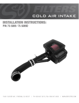
Cold Air Intake System
Instruction Manual P/N: 52-10014D / 52-10014R______________________________
Make: Audi
Model: Q3
Year: 2019-2022
Engine: L4-2.0L (t) 45 TFSI

Page 2
• Please read the entire instruction manual before proceeding.
• Ensure all components listed are present.
• For technical support please call 951-493-7185.
• Ensure you have all necessary tools before proceeding.
• Do not attempt to work on your vehicle when the engine is hot.
• Retain factory parts for future use.
Label
Qty.
Description
Part Number
A1
1
Air Filter (Pro 5R)
24-90069
A2
1
Air Filter (Pro DRY S)
21-90069
B
1
Housing
05-12672B2
C
1
Intake Tube
05-5210014B1
D
1
Coupling, Silicone Reducer
05-01528
E
2
Clamp, #048
03-50007
F
1
Seal Trim
05-00072
Installation will require the following tools:
7mm & 8mm nut drivers,and Torx T25 driver.
Warranty Information available at https://afepower.com/contact#warranty
Emissions Disclaimer: This product is not currently CARB exempt and is not available for purchase in
California or for use on any vehicle registered with the California Department of Motor Vehicles.

Page 3

Page 4
Refer to Figure A for Step 1
Step 1: Remove the engine cover 1 .
REMOVAL
Figure A
1

Page 5
Refer to Figure B for Steps 2-6
Step 2: Using a 7mm nut driver, loosen the clamp 2 at the factory turbo inlet.
Step 3: Disconnect the CCV line 3 from the side of the factory air box lid.
Step 4: Disconnect the smog pump fitting 4 from the factory air box lid.
Step 5: Using a T25 driver unscrew the seven screws securing the air box lid to the lower air box.
Step 6: Remove the factory air box lid and intake tube from the vehicle.
REMOVAL
Figure B
4
2
3

Page 6
Refer to Figure C for Steps 7-8
Step 7: Remove the factory air filter 5 from the vehicle .
Step 8: Remove the factory grate 6 from the bottom of the air box by lifting upwards on it.
REMOVAL
Figure C
6
5

Page 7
Refer to Figure D for Steps 9-10
Step 9: Install the supplied reducer coupling 7 and #048 clamp 8 with the smaller side on your turbo inlet
and tighten using an 8mm nut driver.
Step 10: Place the second #048 clamp 9 loosely around the open end of the coupler.
INSTALL
Figure D
9
8
7

Page 8
Refer to Figure E for Step 11-12
Step 11: Install your aFe POWER air filter into the filter housing 10 by firmly pressing it into the opening
until the small tabs are locked on the outside. Leave the clamp loose on the filter opening.
Step 12: Install the seal trim around the top edge of the filter housing 11.
Figure E
INSTALL
10
11

Page 9
Refer to Figure F for Step 13
Step 13: Install your aFe POWER air filter and housing onto the the lower half of the factory air box. Secure
the aFe POWER filter housing to the factory lower air box using four of the factory screws from the air
box lid
INSTALL
Figure F

Page 10
Refer to Figure G for Step 14-16
Step 14: Install your aFe POWER intake tube first into the opening on the air filter, then rotate it downwards
into the open end of the coupler at the turbo inlet. Use an 8mm nut driver to tighten all clamps.
Step 15: Reconnect the smog pump hose 12 to the fitting on the side of your aFe POWER intake tube.
Step 16: Connect the CCV hose 13 to the barbed fitting on your aFe POWER intake tube.
INSTALL
Figure G
12
13

Page 11
Refer to Figure H for Steps 17-18
Step 17: Reinstall your engine cover.
Step 18: Check that all components are tight and secure. Your installation is now complete. Thank you for
choosing aFe POWER!
NOTE: Check all clamps, and connectors are secure after 100-200 miles
INSTALL
Figure H

/