Page is loading ...

90-DAY LIMITED WARRANTY
If you, as the original owner of this model, discover defects in parts and workmanship within 90 days of purchase, Hobbico will repair or replace
it – at the option of our authorized U.S. repair facility, Hobby Services – without charge. Our liability does not include the cost of shipping to us.
However, Hobby Services will pay shipping expenses to return your model to you. You must provide proof of purchase, such as your original
purchase invoice or receipt, for your model’s warranty to be honored. This warranty does not apply to damage or defects caused by misuse or
improper assembly, service or shipment. Modifications, alterations or repair by anyone other than Hobby Services voids this warranty. We are
sorry, but we cannot be responsible for crash damage and/or resulting loss of kits, motors, accessories, etc.
Your SuperStar EP ARF must be returned directly to Hobby Services for warranty work. The address is: Hobby Services, Attn: Service
Department, 1610 Interstate Drive, Champaign, IL 61822-1067. Phone: (217) 398-0007. Please follow the instructions below when returning
your model. This will help our experienced technicians to repair and return it as quickly as possible.
1. ALWAYS return your entire system, including airplane and radio.
2. Disconnect the receiver battery switch harness and make sure that the transmitter is turned off. Disconnect all batteries.
3. Include a list of all items returned and a THOROUGH, written explanation of the problem and service needed. If you expect the repair to be
covered under warranty, also include your proof of purchase.
4. Include your full return address and a phone number where you can be reached during the day.
If your model is past the 90 day warranty period or is excluded from warranty coverage, you can still receive repair service through Hobby
Services
at a nominal cost. Repair charges and postage may be prepaid or billed COD. Additional postage charges will be applied for non-
warranty returns.
All repairs shipped outside the United States must be prepaid in U.S. funds only. All pictures, descriptions and specifications found in this
instruction manual and on the product package are subject to change without notice. Hobbico maintains no responsibility for inadvertent errors.
ASSEMBLY INSTRUCTIONS
TM
© Copyright 2004 HCAA2052 V1.1
Wingspan: 48.5 in [1232mm]
Wing Area: 400 sq in [26 dm
2
]
Weight: 43.5 oz [1230 g]
Wing Loading: 16.1 oz/sq ft [48 g/cm
2
]
Length: 36.1 in [917mm]
Radio: 4-Channel with three standard servos (required)
Motor: Included
Electronic Speed Control: Included
Motor Battery: 8.4 volt 1700mAh – 3000mAh
WW
WW
II
II
TT
TT
HH
HH
AA
AA
II
II
LL
LL
EE
EE
RR
RR
OO
OO
NN
NN
SS
SS

2
Introduction........................................................2
Safety Precautions ............................................2
Decisions You Must Make.................................3
Radio Equipment...........................................3
Battery Selection...........................................3
Chargers........................................................4
Additional Items Required................................4
Tools..............................................................4
Optional Supplies and Tools..........................4
Important Building Notes..................................4
Kit Contents .......................................................5
Ordering Replacement Parts............................6
Common Abbreviations....................................6
Assemble the Wing............................................7
Install the Stabilizer and Fin.............................9
Install the Landing Gear..................................10
Install the Battery Hatch Cover......................11
Install the Wing Dowels...................................12
Install the Radio...............................................12
Get the Model Ready to Fly ............................15
Check the Control Directions ......................15
Set the Control Throws................................15
Install the Propeller and Motor Battery.........16
Install the Wing on the Fuselage....................16
Balance the Model (C.G.)................................17
Balance the Model Laterally...........................17
Proper Care of Your Motor..............................18
Performance Tips.............................................18
Preflight ............................................................18
Identify Your Model......................................18
Charge the Batteries...................................18
Balance Propellers......................................18
Ground Check.............................................19
Range Check...............................................19
AMA Safety Code (excerpt) ............................19
Check List.........................................................19
Flying..................................................Back Cover
Takeoff ..........................................Back Cover
Flight.............................................Back Cover
Landing.........................................Back Cover
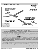
Many modelers have learned how to fly with the
stable, easy to fly, glow powered SuperStar ARF.
Hobbico has taken that stability and ease of flight
and produced an electric version. No more fuel
bottle, starter, glow driver or noise. All you need to
take with you to the flying field is the plane,
transmitter, batteries and charger.When you’re done
flying, just remove the motor battery and put the
plane away until the next flying session. No more
wiping fuel residue off the plane at the end of the
day.So, if you are ready to get started in the exciting
world of electric flight, let’s get this bird in the air.
An electronic speed control with BEC (Battery
Eliminator Circuit) is included with the SuperStar EP.
The BEC eliminates the need for a receiver battery.
The electronic speed control provides power for the
receiver by using the motor battery.As the motor runs,
the voltage of the motor battery is reduced. The
electronic speed control has a preset voltage. Once
the motor battery reaches it, the electronic speed
control switches the motor off. This leaves enough
power in the motor battery to operate the receiver so
that the SuperStar EP can be landed safely.
For the latest technical updates or manual
corrections for the SuperStar EP, visit the web site
listed below and select the Hobbico SuperStar EP.
A “tech notice” box will appear in the upper left
corner of the page if there is new technical
information or changes to this kit.
http://www.hobbico.com/airplanes/index.html
1. Your SuperStar EP should not be considered a
toy, but rather a sophisticated, working model that
functions very much like a full-size airplane.
Because of its performance capabilities, the
SuperStar EP, if not assembled and operated
correctly, could possibly cause injury to yourself or
spectators and damage to property.
Protect Your Model,Yourself & Others
Follow these Important
Safety Precautions
IntroductionTable of Contents

3
2. You must assemble the model according to the
instructions. Do not alter or modify the model, as
doing so may result in an unsafe or unflyable model.
In a few cases the instructions may differ slightly
from the photos. In those instances the written
instructions should be considered as correct.
3. You must take time to build straight, true
and strong.
4. You must use an R/C radio system that is in
first-class condition with the appropriate size servos.
5. You must correctly install all R/C and other
components so that the model operates correctly
on the ground and in the air.
6. You must check the operation of the model
before every flight to insure that all equipment is
operating and that the model has remained
structurally sound. Be sure to check clevises or
other connectors often and replace them if they
show any signs of wear or fatigue.
7. If you are not already an experienced R/C pilot,
you should fly the model only with the help of a
competent, experienced R/C pilot.
Remember: Take your time and follow the
instructions to end up with a well-built model
that is straight and true.
If you have not flown this type of model before, we
recommend that you get the assistance of an
experienced pilot in your R/C club for your first
flights. If you're not a member of a club, your local
hobby shop has information about clubs in your area
whose membership includes experienced pilots.
In addition to joining an R/C club, we strongly
recommend you join the AMA (Academy of Model
Aeronautics). AMA membership is required to fly at
AMA sanctioned clubs. There are over 2,500 AMA
chartered clubs across the country. Among other
benefits, the AMA provides insurance to its
members who fly at sanctioned sites and events.
Additionally, training programs and instructors are
available at AMA club sites to help you get started
the right way. Contact the AMA at the address or
toll-free phone number below:
Academy of Model Aeronautics
5151 East Memorial Drive
Muncie, IN 47302-9252
Tele. (800) 435-9262
Fax (765) 741-0057
Or via the Internet at: http://www.modelaircraft.org
This is a partial list of items required to finish the
SuperStar EP that may require planning or
decision making before starting to build. Order
numbers are provided in parentheses.
Radio Equipment
A 4-channel radio system with 3 standard servos
is required.
Battery Selection
The SuperStar EP was designed to fly on the
recommended 7-cell, 8.4 volt, 2100 mAh motor
battery pack. If you are new to electric airplanes (or
even cars and boats) here is a short explanation of
rechargeable NiCd (Nickel Cadmium) and NiMH
(Nickel-Metal Hydride) batteries. A single cell
rechargeable battery supplies 1.2 volts with no load
(not powering anything). A 7-cell battery pack can
supply 8.4 volts (1.2 volts x 7 cells = 8.4 volts). The
cell rating in mAh (milli-amp-hours) is the amount of
current the battery can supply. If a battery is rated at
2100 mAh, the battery can supply 2.1 amps for 1
hour.This sounds great, flying for an hour on a single
Decisions You Must Make
We, as the kit manufacturer, provide you with a
top quality kit and instructions, but ultimately the
quality and flyability of your finished model
depends on how you build it; therefore, we
cannot in any way guarantee the performance of
your completed model and no representations
are expressed or implied as to the performance
or safety of your completed model.

battery charge! The bad news is that to produce the
power needed to fly an airplane the size of the
SuperStar EP, the motor draws from 15-25 amps.
The current consumption reduces the run time to 5-
8 minutes.The good news is that propellers become
more efficient as the speed of the plane increases.
This lowers the current draw, allowing the plane to fly
longer on a single charge, sometimes up to 20%
longer. Also, with an electronic speed control, the
motor can be throttled back, increasing the flight
time. Most airplanes only need full throttle during
takeoff and climbing maneuvers.
Chargers
A fully charged battery pack will provide an initial
“surge” of power during the first 15 to 30 seconds
of the motor run.Then the power output stays fairly
steady for the next several minutes before dropping
off quickly. If you do not charge your battery
completely, it will not deliver that surge necessary
for a good takeoff and climb out.There are at least
three ways to “peak-charge” your battery pack.
1.The easiest way is with a “peak-detecting” battery
charger. This type of charger will automatically
charge your battery until it is fully charged.
2. The second method of charging your motor
batteries is to monitor the voltage of your battery
pack with a voltmeter. Your charger may have
sockets into which you may plug a voltmeter.If not,
you may insert the probes from the voltmeter into
the rear of the battery plug, making contact with
the metal contacts. As your battery charges, the
voltage will gradually increase.When the battery is
fully charged, the voltage will start to drop. At this
point your battery is fully charged.
3. The third (and least reliable) method of peak-
charging your battery pack is by checking its
temperature. As the battery charges it will remain
cool until it is fully charged. When it reaches the
fully charged state, it will rapidly build up heat.You
can feel this heat with your hand. As soon as the
pack starts to noticeably warm up, disconnect it
from the charger.Do not continue charging if the
battery pack is hot! Overcharging will damage
your battery pack and can result in an explosion.
Tools
In addition to common household tools and hobby
tools, this is the “short list” of the most important
items required to build the SuperStar EP.
❏ Hobby knife (HCAR0105)
❏ #11 blades (HCAR0211)
❏ Small Phillips and flat blade screwdrivers
❏ Pliers (HCAR0630)
❏ Crescent wrench
❏ Drill with a 1/32" (.8mm) and 3/32" (2.4mm) drill bit
Optional Supplies and Tools
Here is a list of optional tools that will help you
build the SuperStar EP.
❏ Great Planes CG Machine
™
(GPMR2400)
❏ Great Planes AccuThrow
™
Deflection Gauge (for
measuring control throws, GPMR2405)
•Photos and sketches are placed before the step
they refer to. Frequently you can study photos in
following steps to get another view of the same parts.
•Should repairs ever be required, the SuperStar
EP’s covering can be patched with Top Flite
®
MonoKote
®
purchased separately. MonoKote is
packaged in six-foot rolls, but some hobby shops
also sell it by the foot. If only a small piece of
MonoKote is needed for a minor patch, perhaps a
fellow modeler would give you some. MonoKote is
applied with a model airplane covering iron, but in
an emergency a regular iron could be used.
Important Building Notes
Additional Items Required
4

5
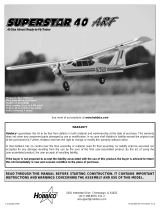
Kit Contents
1. Fuselage w/Motor (1)
2. Stabilizer and Elevator (1)
3. Right Wing w/ailerons (1)
4. 9 x 5.5 Propeller (1)
5. Steel Wing Joiner Rod (1)
6. Foam Wheels (2)
7. 1mm x 520mm Pushrods (2)
8. Fin and Rudder (1)
9. Aileron Pushrod Wires (2)
10. Aileron Servo Tray (1)
11. Left Wing w/ailerons (1)
12. Wing Dowels (2) & Caps (4)
13. Hook and Loop Material (4)
14. Main Landing Gear Wires (2)
Before starting to build, use the Kit Contents list to take an inventory of this kit to make sure it is
complete and inspect the parts to make sure they are of acceptable quality. If any parts are missing or
are not of acceptable quality, or if you need assistance with assembly, contact Hobbico Product
Support. When reporting defective or missing parts, use the part names exactly as they are written in
the Kit Contents list on this page.
Hobbico Product Support
Phone: (217) 398-8970
Fax: (217) 398-7721
E-mail: airsupport@hobbico.com
Parts (Photographed)
(1) 2.5mm x 25mm Alignment Pin
(8) Rubberbands
(2) Nylon Landing Gear Straps
(2) Small Nylon Control Horns
(1) Nylon Tail Skid
(2) Brass Screw-lock Pushrod
Connectors
(2) Nylon Screw-lock Connector
Retainers
(2) 4-40 x 1/4" Pan Head Screws
(4) 3/32" Wheel Collars
(5) 2.5mm x 8mm Sheet Metal Screws
(1) Aluminum Battery Hatch Retainer
(4) 2-56 x 5/8" Machine Screws
(4) 4-40 Set Screws
(2) 2-56 Nuts
(2) #2 Washers
(1) Wing Joiner Tape
(1) Electronic Speed Control
(1) Prop Adapter
(1) Steel Anti-Rotate Pin
Parts (Not Photographed)
9
10
11
12
13
14
1
2
3
4
5
6
7
8

0" 1" 2" 3" 4" 5"
0 10 20 30 40 50 60 70 80 90 100 110 120 130
Inch Scale
Metric Scale
6
Ordering Replacement Parts
To order replacement parts for the Hobbico SuperStar EP, use the order numbers in the Replacement
Parts List that follows. Replacement parts are available only as listed. Not all parts are available
separately (a rudder cannot be purchased separately, but is only available with the tail set).Replacement
parts are not available from Product Support, but can be purchased from hobby shops or mail
order/Internet order firms. Hardware items (screws, nuts, bolts) are also available from these outlets. If
you need assistance locating a dealer to purchase parts, visit www.hobbico.com and click on “Where
to Buy.” If this kit is missing parts, contact Hobbico Product Support.
Item Description
How to Purchase
Missing pieces Contact Product Support
Plans Construction Plans Plans are not available for ARF models
Hardware Individual hardware items Contact your hobby supplier
HCAA3034 SuperStar EP Wing w/ail Kit Contact your hobby supplier
HCAA3036 SuperStar EP Fuse Kit Contact your hobby supplier
HCAA3037 SuperStar EP Tail Set Contact your hobby supplier
HCAA3039 Motor Contact your hobby supplier
HCAA3040 Prop / Prop Adapter Contact your hobby supplier
HCAA3041 Electronic Speed Control Contact your hobby supplier
HCAA3038 SuperStar EP Landing Gear Contact your hobby supplier
Warning: The motor, electronic speed control, and prop supplied with the SuperStar EP are a matched
set and must be used together. Should you choose to change one or more of the supplied components,
you will void your warranty on this product.
To convert inches to millimeters, multiply inches by 25.4
1/64" = .4mm
1/32" = .8mm
1/16" = 1.6mm
3/32" = 2.4mm
1/8" = 3.2mm
5/32" = 4mm
3/16" = 4.8mm
1/4" = 6.4mm
3/8" = 9.5mm
1/2" = 12.7mm
5/8" = 15.9mm
3/4" = 19mm
1" = 25.4mm
2" = 50.8mm
3" = 76.2mm
6" = 152.4mm
12" = 304.8mm
15" = 381mm
18" = 457.2mm
21" = 533.4mm
24" = 609.6mm
30" = 762mm
36" = 914.4mm
Metric Conversions

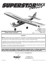
❏ 1. Remove the tape and separate the ailerons
from the wing and the elevators from the stab. Use
a covering iron with a covering sock on high heat to
tighten the covering if necessary. Apply pressure
over sheeted areas to thoroughly bond the
covering to the wood.
❏❏2. Drill a 3/32" hole, 1/2" deep in the center of
each hinge slot to allow the CA to "wick" in.Follow-
up with a #11 blade to clean out the slots. Hint: If
you have one, use a high-speed rotary tool to drill
the holes.
❏❏3.Use a sharp #11 blade to cut a strip of covering
from the hinge slots in the wing and aileron.
❏❏4.Cut eight 3/4" x 1" [25mm] hinges from the CA
hinge strip.Snip off the corners so they go in easier.
❏❏5 Test fit the ailerons to the wing with the hinges.
If the hinges don't remain centered, stick a pin through
the middle of the hinge to hold it in position.
❏❏6. Remove any pins you may have inserted
into the hinges. Adjust the aileron so there is a
small gap between the LE of the aileron and the
wing.The gap should be small, just enough to see
light through or to slip a piece of paper through.
❏❏7. Apply six drops of thin CA to the top and
bottom of each hinge, waiting a few seconds
between drops to allow the CA to soak in. Do not
use CA accelerator. After the CA has fully
hardened, test the hinges by pulling on the aileron.
❏ 8. Repeat steps 1- 6 for the left wing panel.
Assemble the Wing
7

❏ 9. Insert the 7/32" x 6-7/8" [5.5mm x 174.6mm]
steel wing joiner rod in the forward hole in the wing
root rib of the left wing half. Insert the 3/32" x 1"
[2.3mm x 25.4mm] anti-rotation pin in the aft hole in
the wing root rib.
❏ 10. Join the two wing halves together.
❏ 11. On the top and bottom of the wing, apply the
1" [25.4mm] wide wing joiner tape, centering on
the joint between the two wing halves.
❏ 12. Glue the aileron servo tray onto the tabs in
the servo opening.
❏ 13. Screw the aileron torque rod horns onto the
aileron torque rod wires.
❏ 14. Place the servo into the servo tray. Drill a
1/16" [1.6mm] hole through each of the mounting
holes and secure the servo to the tray with the
hardware provided with the servo.
8

❏ 15. Locate two .074" x 6" [.074" x 152mm] pushrod
wires. Screw a nylon clevis onto the threaded end of
the wires 20 full turns. Install a silicone clevis keeper
onto the clevis and then install the clevis in the hole in
the aileron torque rod horns.
❏ 16. Ensure that the aileron servo is centered.
Enlarge the outermost holes in the servo arm with
a Hobbico Servo Horn Drill (or a #48 or 5/64"
[2mm] drill bit). Center the aileron and align the
wire pushrod with the hole in the end of the servo
arm. Using a marker, mark the location where the
wires align with the hole in the servo arm. On that
mark make a 90 degree bend. From the bend
measure an additional 3/16" [4.8mm].Then, cut off
the excess pushrod wire.
❏ 17. Install the wire into the hole in the servo arm
using a nylon FasLink as shown in the sketch.
❏ 1. Use a sharp hobby knife to trim the covering
from the slots for the stabilizer and fin at the aft end
of the fuselage. You can feel the slots for the
stabilizer on both sides of the fuselage.The slot is
located close to the red stripe. Also cut the wood
block from the aft end of the slots. The slot for the
fin is in the top of the fuselage.
❏ 2. Use a sharp hobby knife to trim the covering
from the two holes at the front of the stabilizer.
❏ 3.Use a sharp hobby knife to trim the covering from
the two holes on the bottom aft end of the fuselage.
Install the Stabilizer and Fin
9

❏ 4. Insert the stabilizer and center it in the
stabilizer slot. The side with the red, yellow and
blue stripe faces upward. The two holes through
the stabilizer should be aligned with the fin slot in
the top of the fuselage.
❏ 5. Insert the fin in the fin slot. The two threaded
rods go through the two holes in the stabilizer and
out the two holes in the bottom of the fuselage.
❏ 6. Place a #2 washer over each fin rod and
secure the fin to the fuselage with #2-56 nuts.Do
not overtighten the nuts and crush the wood. The
nuts should be just tight enough to prevent the
stabilizer from moving side to side.
❏ 1. On the bottom of the fuselage, at the aft end,
are two small holes. Remove the covering from
these holes with a hobby knife.
❏ 2.Insert the nylon tail skid in the holes.If the tail
skid fits loosely, a drop of glue in each hole will
secure the tail skid.
❏ 3. Insert the two main landing gear wires in the
holes, in the slot, at the front of the fuselage.
Install the Landing Gear
10
2-56 Nut

❏ 4. Secure the main landing gear wires to the
fuselage with two nylon landing gear straps and
four 2.5mm x 8mm sheet metal screws. Note: The
pilot holes are predrilled under the covering and
the covering only needs to be pierced.
❏ 5. Slide a 3/32" [2.4mm] wheel collar on one of
the landing gear wires, followed by a wheel and a
second wheel collar. Secure the wheel collars to
the landing gear wires with 4-40 set screws.
Repeat the process for the second landing gear
wire. Make sure the wheels rotate freely.
❏ 1.The battery hatch cover has holes cut in the
plywood. Use a hobby knife with a sharp blade to
trim the covering from over the holes.
❏ 2. Use a 2.5mm x 8mm sheet metal screw to
attach the aluminum battery hatch retainer to the
fuselage at the front of the battery hatch. Note that
the pilot hole for the screw has been drilled under the
covering and the covering only needs to be pierced.
Tighten the screw completely, then back it off 1/8 of
a turn. The hatch retainer should require some
pressure to rotate it. If it is too loose, it may rotate
during flight, allowing the battery hatch to come off.
❏ 3.To make the battery straps, overlap the hook
and loop material by approximately 2" [50.8mm].
Insert the battery straps, from the inside the
fuselage, through the slot in one side of the battery
tray and back out the slot on the other side of the
battery tray. Install a front and back battery strap.
Install the Battery Hatch Cover
11
2.5 x 8mm
5/32"
Wheel
Collar
2.5 x 8mm

❏ 1. Trim the covering from over the wing dowel
holes on both sides of the fuselage.The holes are
located at the front and back of the wing saddle.
❏ 2.Insert and center the 1/4" x 4" [6.4mm x 101mm]
wing dowels in the holes in the fuselage.
❏ 3. Slide a plastic dowel cap over one end of the
wing dowel.Secure the dowel cap with a 2.5mm x
8mm sheet metal screw. Install the other three
dowel caps and secure them with 2.5mm x 8mm
sheet metal screws.
❏ 1. Make a strap, the same way you made the
battery strap.Route the strap through the front hole
in the battery tray and back through the middle
hole.Position the electronic speed control (ESC)
on the battery tray and secure it with the strap,
leaving the metal heat sink exposed. Trim off the
excess strap.
❏ 2.Connect the red and black wires from the motor
to the red and black wires from the electronic speed
control. Make sure the wires are securely
connected. If any of the metal connector is visible,
wrap it in electrical tape to prevent the wires from
shorting and damaging the electronic speed control.
❏ 3. Install the on/off switch in the opening under
the second window on the left side of the fuselage.
Install the RadioInstall the Wing Dowels
12
2.5 x 8mm

❏ 4. Follow the instructions that came with your
radio system to properly install the rubber
grommets and metal eyelets on your servos.Place
two servos in the servo tray as shown. Position
them so that they are approximately 1/8" [3.2mm]
from the side of the servo tray.
❏ 5. Drill a 1/32" [.8mm] pilot hole through the
servo tray at each grommet. Secure the servos to
the servo tray using the screws included with the
radio system.
❏ 6. Make a fourth strap, the same way you made
the two battery straps. Route the strap through the
back hole in the battery tray and back through the
middle hole.Plug the two servos and the electronic
speed control into the receiver. Wrap the receiver
in foam rubber and position it on the battery tray,
securing it with the strap.Trim off the excess strap.
❏ 7. Trim two servo horns so that one arm remains
as shown.Keep one of the arms that you trimmed off
for an antenna strain relief that will be installed later.
❏ 8. Connect the charged motor battery to the
electronic speed control. Switch on the transmitter
and then the electronic speed control. Center the
rudder and elevator trims on your transmitter.
IMPORTANT: To avoid accidents, do not install the
propeller until after all the control checks have
been completed.
❏ 9. In both servo arms, install a screw-lock
pushrod connector body in the hole approximately
3/8" [9.5mm] from the center.Press a nylon retainer
on to the pushrod connector to secure it to the servo
arm.Note: The servo arms have been painted white
for better clarity in the instructions.
❏ 10. Install the servo arms on the rudder and
elevator servos so that they are perpendicular to
the centerline of the servo. Also use a hobby knife
to trim the outer pushrod tubes approximately 1/8"
[3.2mm] in front of the former.
❏ 11. Separate the back plate from one of the
small nylon control horns.
❏ 12. Install the z-bend of one of the pushrods in
the outer hole of the control horn.
Trim Off
13
Retainer

❏ 13. Locate and pierce the covering from the
rudder pushrod exit hole on the top of the fuselage,
left of the fin. Note: An easy method to locate the
exit hole under the covering is to insert the wire
pushrod into the outer pushrod tube just behind the
rudder servo and note where the pushrod wire
comes out under the covering.
❏ 14. From the aft end of the model, reinsert the
pushrod wire with the control horn on it into the
rudder outer pushrod tube. Guide the end of the
pushrod through the screw-lock pushrod connector
on the rudder servo. Position the control horn on
the leading edge of the rudder so that the pushrod
holes are aligned with the joint between the rudder
and fin.If it is not aligned properly with the joint, the
plane will turn better one way than the other.
❏ 15. Mark the two control horn mounting hole
locations. Move the control horn out of the way and
drill a 3/32" [2.4mm] hole through the rudder, at both
hole locations. Insert two 2-56 x 5/8" machine screws
through the control horn and the rudder. Install the
control horn back plate on the other side of the rudder.
❏ 16. With the transmitter and electronic speed
control switched on, set the rudder to neutral
(straight with the fin). Secure the rudder pushrod in
the screw-lock pushrod connector with a 4-40 x 1/4"
slotted head screw. Cut off the excess pushrod.
❏ 17. Repeat the same process to install the
elevator pushrod and control horn.The exit hole for
the elevator pushrod is on the right side of the
fuselage, under the stabilizer.
❏ 18. Make a strain relief by trimming the servo
arm you cut off previously, so that only two holes
remain. Thread the receiver antenna through the
first hole and back through the second hole.
Position the strain relief so that it is approximately
6" [152.4mm] from the receiver.The strain relief will
hit the side of the fuselage, preventing the receiver
antenna from being pulled loose from the receiver.
❏ 19. Drill a 3/32" [2.4mm] hole 3/4" [19mm]
behind the aft edge of the wing saddle. Route the
receiver antenna out the hole and tape it to the
upper side of the fin. Do not shorten the receiver
antenna. Shortening the receiver antenna will
reduce the receiver’s range.
14
2-56 x 5/8"
Machine Screw
4-40 x 1/4" Slotted
Head Screw

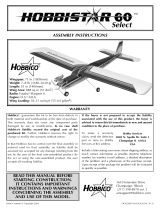
Check the Control Directions
❏ 1. Switch on the transmitter, connect the motor
battery to the electronic speed control and switch
on the speed control. Center the trims. If
necessary, remove the servo arms from the servos
and reposition them so they are centered.Reinstall
the screws that hold on the servo arms.
❏ 2. With the transmitter and receiver still on,
check all the control surfaces to see if they are
centered.The top of the elevator should be flat with
the top of the stabilizer and the rudder should be
inline with the fin. If necessary, loosen the 4-40
slotted head screws in the screw-lock pushrod
connectors and adjust the pushrods to center the
control surfaces.
❏ 3.Make certain that the control surfaces respond
in the correct direction as shown in the diagram. If
any of the controls respond in the wrong direction,
use the servo reversing switch in the transmitter to
reverse the servos connected to those controls.Be
certain the control surfaces have remained
centered.Adjust if necessary.With the prop still not
installed, check that the throttle lever is in the off
position or low throttle.To start the motor, the start
button must be pressed after the electronic speed
control is switched on.
Set the Control Throws
Use a Great Planes AccuThrow (or a ruler) to
accurately measure and set the control throw of
each control surface as indicated in the chart that
follows. If your radio does not have dual rates, we
recommend setting the throws at the low rate
setting. NOTE: The throws are measured at the
widest part of the elevator and rudder.
IMPORTANT: The SuperStar EP has been
extensively flown and tested to arrive at the
throws at which it flies best.Flying your model at
these throws will provide you with the greatest
chance for successful first flights. If, after you
have become accustomed to the way the
SuperStar EP flies, you would like to change the
throws to suit your taste, that is fine. However,
too much control throw could make the model
difficult to control, so remember, “more is not
always better.”
These are the recommended control surface throws:
Low Rate High Rate
Elevator: 1/4" [6.4mm] up 7/16" [11mm] up
1/4" [6.4mm] down 7/16" [11mm] down
Rudder: 3/8" [9.5mm] right 5/8" [15.9mm] right
3/8" [9.5mm] left 5/8" [15.9mm] left
Get the Model Ready to Fly
15

❏ 1. Slide the aluminum prop adapter over the
motor shaft. Slide the aluminum prop adapter
retainer over the prop adapter. Note: The hole
through the prop adapter retainer is beveled. The
side with the larger hole goes on first.
❏ 2. Slide the propeller onto the prop adapter. The
front of the prop has 9 x 5.5 lettering molded into it.
Secure the propeller to the prop adapter with the
aluminum prop washer and prop nut.Hold the prop
adapter retainer while tightening the prop nut. Make
sure the prop is securely attached to the motor shaft.
❏ 3. Insert the motor battery in the battery
compartment. Secure the battery with a hook and
loop strap. It is not necessary to plug the motor
battery into the electronic speed control until you
are ready to fly.
❏ 4. Insert the lip on the battery hatch under the
sheeting at the aft end of the battery compartment.
Lock the battery hatch in position by rotating the
battery hatch retainer over the battery hatch.
❏ 1. Center the wing on the fuselage. Place a
rubberband around the aft wing hold-down dowel
and stretch it over the top of the wing, placing it
around the forward wing hold-down dowel. Attach a
second rubberband on the other side of the fuselage.
❏ 2. Again place a rubberband around the aft wing
hold-down dowel and stretch it over the top of the
wing, this time crossing over to the other side of the
fuselage before placing it around the forward wing
hold-down dowel.
❏ 3. Repeat the process to install the four
remaining rubber bands.
Install the Wing on the Fuselage
Install the Propeller and Motor Battery
16

At this stage the model should be in ready-to-fly
condition with all of the systems in place including
the motor and prop, electronic speed control,
motor battery, radio system and wing.
❏ 1. Use a felt-tip pen or 1/8"-wide tape to
accurately mark the C.G. range on the bottom of
the wing on both sides of the fuselage. The C.G.
range is located between 2-1/2" [63.5mm] and
2-7/8" [73mm] back from the leading edge of
the wing.
❏ 2. With the wing attached to the fuselage and all
parts of the model installed (ready to fly), place the
model right-side up on a Great Planes CG Machine
™
,
or lift it right-side up within the balance range
you marked.
❏ 3. Have an assistant stand 6' to 8' to the side of
the model. As you lift the model, have the assistant
observe the stabilizer. If the plane is properly
balanced, the stabilizer will be level.If the tail drops,
the model is “tail heavy” and weight must be added
to the nose to balance.If the nose drops, the model
is “nose heavy”and weight must be added to the tail
to balance. If additional weight is required, use
Great Planes (GPMQ4485) “stick-on” lead. A good
place to add stick-on nose weight is beside the
motor on the fuselage side. Begin by placing
incrementally increasing amounts of weight on the
fuse until the model balances. Once you have
determined the amount of weight required, it can be
permanently attached. If required, tail weight may
be added to the underside of the stabilizer.
❏ 4. IMPORTANT: If you found it necessary to add
any weight, recheck the C.G. after the weight has
been installed.
❏ 1.With the wing level, have an assistant help you
lift the model by the motor shaft and the bottom of
the fuselage, under the TE of the stabilizer.Do this
several times.
❏ 2. If one wing always drops when you lift the
model, it means that side is heavy. Balance the
airplane by adding weight to the other wing tip. An
airplane that has been laterally balanced will
track better in loops and other maneuvers.
Balance the Model Laterally
2-11/16"
Your model must be balanced within this C.G.
range.Balancing your model forward or aft of the
C.G. range will change its flying characteristics.
With the plane balanced at the forward C.G. the
plane will fly smoother and be more stable, but it
may require more speed for takeoff and make it
more difficult to slow for landing.This is the best
location for the C.G. if you are new to R/C flying.
With the C.G. at the back of the C.G. range the
plane will be more maneuverable, but could also
become too difficult for you to control. In any
case, do not balance your model outside the
recommended range.
More than any other factor, the C.G. (balance
point) can have the greatest effect on how a
model flies and may determine whether or not
your first flight will be successful. If you value this
model and wish to enjoy it for many flights,
DO NOT OVERLOOK THIS IMPORTANT
PROCEDURE. A model that is not properly
balanced will be unstable and possibly unflyable.
Balance the Model (C.G.)
17

❏ 1. The included motor will benefit from a short
“break-in”by running it without the propeller for at
least 1/2 hour.This will seat the motor brushes on
the commutator, insuring that the motor will provide
full power for your first flight and extending motor
life.If you notice a decrease in motor power after a
number of flights, it may be due to carbon build-up
on the brushes or commutator. To remove this
build-up, repeat the above break-in procedure.
❏ 2. The bronze bushings in the motors are self
lubricating, but their life may be extended by
applying a very small amount of light machine oil to
the point where the motor shaft contacts the
bushings after every hour or two of run time. Note:
A drop of oil is far too much.You should apply the oil
with a toothpick.Never oil the inside of the motor.
❏ 3. Using multiple battery packs to run the motor
for successive flights may cause the motor to
become excessively hot.We recommend at least a
10 to 15 minute cool-down period between flights.
❏ 4.The ideal power source for the SuperStar EP is
a 7-cell, 8.4 volt 1700 - 3000 mAh battery pack.The
use of a higher voltage battery will reduce the motor
life and will also require modifications to the battery
compartment to allow the extra battery cells to fit.
❏ 1. A new battery pack should be “cycled” for best
results. You should peak charge the battery, then
discharge it almost completely by actually running
your motor with the propeller attached. Do this 3 or
4 times on the ground before actually flying.Be sure
you remove the battery from the airplane between
each cycle and allow it to cool before recharging.
❏ 2. Examine your propeller for irregularities
caused by the injection molding process. Carefully
remove the imperfections with fine sandpaper.
Also, make sure your propeller is balanced.
Vibration from the propeller will decrease the
performance and life of the motor.
Identify Your Model
No matter if you fly at an AMA sanctioned R/C club
site or if you fly somewhere on your own, you
should always have your name, address, telephone
number and AMA number on or inside your model.
It is required at all AMA R/C club flying sites and
AMA sanctioned flying events. Fill out the
identification tag on the back of this manual and
place it on or inside your model.
Charge the Batteries
Follow the battery charging instructions that came
with your radio control system to charge the
transmitter.You should always charge your transmitter
batteries the night before you go flying and at other
times as recommended by the radio manufacturer.
Balance Propellers
Carefully balance your propeller before you fly. An
unbalanced prop can be the single most significant
cause of vibration that can damage your model. Not
only will mounting screws and bolts loosen, possibly
with disastrous effect, but vibration may also damage
your radio receiver and electronic speed control.
We use a Top Flite
®
Precision Magnetic Prop
Balancer
™
(TOPQ5700) in the workshop and keep a
Great Planes
®
Fingertip Prop Balancer (GPMQ5000)
in our flight box.
Install the propeller on the prop balancer and note
which propeller blade rotates to the bottom.This is the
heavy blade.To balance the prop, lightly sand the back
side of the heavy blade and then recheck it on the prop
balancer. This process may need to be repeated
several times before the propeller is balanced.
Preflight
Performance Tips
Proper Care of Your Motor
18

Ground Check
After you break-in the motor on the model, inspect
the model closely to make sure all screws
remained tight and that the prop, pushrods and
pushrod connectors are secure.
Range Check
Whenever you go to the flying field, check the
operational range of the radio before the first flight of
the day. First, make sure no one else is on your
frequency (channel). Have an assistant hold the
model, staying clear of the prop. With your
transmitter on, you should be able to walk at least
100 feet away from the model and still have control.
While you work the controls, have your assistant tell
you what the control surfaces are doing.Repeat this
test with the motor running at various speeds. If the
control surfaces are not always responding correctly,
do not fly! Find and correct the problem first.Look for
loose servo connections or corrosion, loose bolts
that may cause vibration, a defective on/off switch,
low battery voltage, a damaged receiver antenna, or
a receiver crystal that may have been damaged
from a previous crash.If the radio appears to only be
affected when the motor is running, try moving your
receiver and receiver antenna farther away from the
motor battery and motor. Also, installing a couple
more capacitors on the motor may help. The
capacitors should be soldered from the terminals to
the motor case and from one terminal to the other.
Read and abide by the following Academy of
Model Aeronautics Official Safety Code:
General
1. I will not fly my model aircraft in sanctioned events, air
shows, or model flying demonstrations until it has
been proven to be airworthy by having been
previously successfully flight tested.
2.I will not fly my model aircraft higher than approximately
400 feet within 3 miles of an airport without notifying the
airport operator. I will give right of way to and avoid flying
in the proximity of full scale aircraft.Where necessary, an
observer shall be used to supervise flying to avoid having
models fly in the proximity of full scale aircraft.
3.Where established, I will abide by the safety rules for the
flying site I use and I will not willfully and deliberately fly my
models in a careless, reckless and/or dangerous manner.
7.I will not fly my model unless it is identified
with my name and address or AMA number, on or in
the model.
9.I will not operate models with pyrotechnics (any device
that explodes, burns, or propels a projectile of any kind).
Radio Control
1. I will have completed a successful radio equipment ground
check before the first flight of a new or repaired model.
2. I will not fly my model aircraft in the presence of
spectators until I become a qualified flier, unless
assisted by an experienced helper.
3. I will perform my initial turn after takeoff away from the
pit or spectator areas and I will not thereafter fly over
pit or spectator areas, unless beyond my control.
4. I will operate my model using only radio control
frequencies currently allowed by the Federal
Communications Commission.
❏ 1. Check the C.G. according to the
measurements provided in the manual.
❏ 2. Be certain the motor battery and receiver are
securely mounted in the fuse.
❏ 3.Extend your receiver antenna and make sure it
has a strain relief inside the fuselage to keep
tension off the solder joint inside the receiver.
❏ 4. Balance your model
laterally
as explained in
the instructions.
❏ 5. Use threadlocking compound to secure
critical fasteners such as the cap screws in
the screw-lock pushrod connectors.
❏ 6. Confirm that all controls operate in the
correct direction and the throws are set up
according to the manual.
❏ 7.Make sure all servo arms are secured to the
servos with the screws included with your radio.
During the last few moments of preparation your
mind may be elsewhere. anticipating the
excitement of the first flight. Because of this, you
may be more likely to overlook certain checks
and procedures that should be performed before
the model is flown.To help avoid this, a checklist
is provided to make sure these important areas
are not overlooked. Many are covered in the
instruction manual, so where appropriate, refer
to the manual for complete instructions. Be sure
to check the items as off they are completed.
Check List
AMA Safety Code (excerpts)
19

❏ 8. Use an incidence meter to check the wing for
twists and attempt to correct before flying.
❏ 9. Balance your propeller.
❏ 10. Check that the prop nut is tight and that the
prop adapter is secure on the motor shaft.
❏ 11.Place your name, address, AMA number and
telephone number on or inside your model.
❏ 12. If you wish to photograph your model, do so
before your first flight.
❏ 13. Range check your radio when you get to
the flying field.
The SuperStar EP is a great-flying model that flies
smoothly and predictably. The SuperStar EP possesses
the self-recovery characteristics of a primary R/C trainer.
However, if you have never flown an R/C plane before,
we recommend you get some help from an experienced
R/C pilot for your first few flights.
Takeoff
Switch on the transmitter and make sure the throttle stick is
back (pulled towards you). Switch on the electronic speed
control.If you have dual rates on your transmitter, set them to
low. For the first flight have an assistant hand launch the
plane for you.This will allow you to have both hands on the
transmitter in case the plane is out of trim. To launch the
SuperStar EP, grip the plane under the wing, keeping all body
parts away from the propeller. Switch the motor on and toss
the plane level into the wind.Allow the SuperStar EP to gain
speed and climb out at a shallow angle before turning. The
SuperStar EP can also take off from a hard surface.
Flight
Take it easy with the SuperStar EP for the first few flights,
gradually getting acquainted with it as you gain confidence.
Adjust the trims to maintain straight and level flight.After flying
around for a few minutes and while still at a safe altitude with
plenty of battery power remaining, practice slow flight and
execute practice landing approaches by reducing the throttle
to see how the model handles at slower speeds.Add power
to see how she climbs as well. Continue to fly around,
executing various maneuvers and making mental notes (or
having your assistant write them down) of what trim or C.G.
changes may be required to fine tune the model so it flies the
way you like. Mind your battery power, but use this first flight
to become familiar with your model before landing.
Landing
With electric planes it's best to land with some battery power
remaining. This will allow you to abort the landing and go
around again if needed.To initiate a landing approach, lower
the throttle while on the downwind leg.Allow the nose of the
model to pitch downward to gradually bleed off altitude.
Continue to lose altitude, but maintain airspeed by keeping
the nose down as you turn onto the crosswind leg. Make
your final turn toward the runway (into the wind) keeping the
nose down to maintain airspeed and control. Level the
attitude when the model reaches the landing area,
modulating the throttle as necessary to maintain your glide
path and airspeed. If you are going to overshoot, smoothly
advance the throttle (always ready on the right rudder to
counteract torque) and climb out to make another attempt.
When you're ready to make your landing flare and the model
is a foot or so off the ground, smoothly increase up elevator
until it gently touches down.
One final note about flying your model.Have a goal or flight
plan in mind for every flight. This can be learning a new
maneuver(s), improving a maneuver(s) you already know, or
learning how the model behaves in certain conditions (such
as on high or low rates).This is not necessarily to improve
your skills (
though it is never a bad idea!
), but more
importantly so you do not surprise yourself by impulsively
attempting a maneuver and suddenly finding that you've run
out of time, altitude or airspeed. Every maneuver should be
deliberate, not impulsive. For example, if you're going to do
a loop, check your altitude, mind the wind direction
(anticipating rudder corrections that will be required to
maintain heading), remember to throttle back at the top and
make certain you are on the desired rates (high/low rates).
A flight plan greatly reduces the chances of crashing your
model just because of poor planning and impulsive moves.
Remember to think.
Have a ball! But always stay in control
and fly in a safe manner.
GOOD LUCK AND GREAT FLYING!
CAUTION (THIS APPLIES TO ALL R/C AIRPLANES): If,
while flying, you notice any unusual sounds, such as a low-
pitched “buzz,” this may indicate control surface
flutter
.
Because flutter can quickly destroy components of your
airplane, any time you detect flutter you must immediately
cut the throttle and land the airplane! Flutter is when a control
surface vibrates back and forth very quickly.This vibration can
cause the control surface to come off the plane. Check all
servo grommets for deterioration (this may indicate which
surface fluttered) and make sure all pushrod linkages are
secure and free of play. If the control surface fluttered once, it
probably will flutter again under similar circumstances unless
you can eliminate the free-play or flexing in the linkages.Here
are some things which can cause flutter: Not mounting control
horns solidly; Side-play of pushrod in guide tube caused by
tight bends; Poor fit of Z-bend in control horn; Excessive
play
or
backlash
in servo gears; and Insecure servo mounting.
Flying
/