Extech Instruments EC600 User manual
- Category
- Measuring, testing & control
- Type
- User manual
This manual is also suitable for

User's Guide
Digital Conductivity / pH Meter
Model EC600
www.burntec.comwww.burntec.com

EC600 V2.0 4/10
2
Introduction
Congratulations on your purchase of the Extech Conductivity / pH meter. For best
results, please read the entire manual before use.
The EC600 meter measures Conductivity, pH, and temperature parameters.
Conductivity measurements also yield TDS (total dissolved solids), Salinity, and
Resistivity readings.
The built-in microprocessor provides automatic calibration, automatic temperature
compensation, data storage, and self-diagnostics. The meter can recognize up to 13
types of pH standard buffer solutions and 8 types of Conductivity standards.
The meter’s digital filter improves measurement speed and accuracy.
Two special modes (for distilled water and distilled water mixed with ammonia) are
provided.
The meter offers a backlit LCD display and is dust-proof and water-proof, meeting the
IP57 rating
This meter is shipped fully tested and calibrated and, with proper use, will provide years
of reliable service.
Supplied Equipment List
• EC6000 Meter
• Conductivity and pH Electrodes
• Standard pH buffer solutions (4.00pH, 7.00pH, and 10.01pH) / 50ml
• Standard Conductivity solution (1413µS/cm) / 50ml
• Screwdriver (for removing battery compartment)
• Batteries (2 x ’AA’ 1.5V)
• User’s Guide
• Carrying Case
www.burntec.comwww.burntec.com

EC600 V2.0 4/10
3
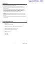
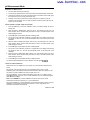
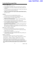
Meter Description
1. LCD Display (detailed in section below)
2. Rubber protective jacket (remove to access the rear battery compartment)
3. Keypad (detailed in section below)
4. Electrode connection jack
5. Electrode plug
6. Electrode cable
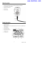
Display Description
1. Measurement type icon
2. Measured reading
3. 888 (Stored data serial number), M+ (measurement to be stored icon), RM (reading to
be recalled icon)
4. Units of measure
5. Temperature reading
6. Stable measurement icon
7. Calibration icons
8. Low battery icon
www.burntec.comwww.burntec.com

EC600 V2.0 4/10
4
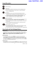
Keypad Description
The meter has five (5) front panel function keys:
ON/OFF Power Key
Calibration Key:
a) When taking a measurement, press this key to enter the calibration mode
b) When in the programming mode, press this key to change the displayed
number or the ON/OFF state
Function Key
a) In pH measuring mode, one short press switches between pH and mV
measuring modes. One long press (>2s) enters the parameter setting mode.
Subsequent presses will scroll through the available parameters.
b) In other measuring modes, press and hold to enter the parameter setting
modes. The meter will scroll through the available parameters
Backlight and ENTER Key
a) In the measurement mode, momentary presses toggle the backlight on and off
b) When in the programming or calibration mode, press to ENTER data
c) When in the pH mode, press and hold to change the resolution in the range of
0.01 to 0.1pH
d) When in the Conductivity mode, press and hold to scroll through the TDS,
Salinity, Resistivity, and Conductivity modes
MEMORY STORE and RECALL Key
a) In the measurement mode, momentary presses store the displayed readings.
Press and hold for at least 2 seconds to recall a saved reading
b) In programming mode, press to change the displayed number or ON/OFF state
Store, Recall, and Clear Datalogger Memory
STORE Readings
The meter can store up to 100 pH, 100 mV, and 100 Conductivity readings for a total of
300 data points. To store a reading, wait until the reading stabilizes (the smiling face icon
appears when the reading stabilizes). Press the M+/RM key momentarily to store a
reading. The M+ icon appears and the data point serial number increments.
RECALL Readings
In the measurement mode, press the M+/RM key to recall the most recently stored
reading. RM and the data point serial number for the displayed reading will appear on the
LCD. The measurement information will appear on the lower right hand side of the LCD.
Use the CAL or M+/RM buttons to scroll the remaining stored readings. Press the ENTER
key to return to the normal measurement mode.
CLEAR Readings
From the RECALL mode, press and hold the ENTER key for at least five (5) seconds. The
LCD display will show ‘CLR’ indicating that all of the stored readings have been erased.
www.burntec.comwww.burntec.com

EC600 V2.0 4/10
5
The unit will automatically return to the normal measurement mode after approximately 2
seconds.
www.burntec.comwww.burntec.com

EC600 V2.0 4/10
6
pH Measurement Mode
Preparation for Measurement
1. Turn the meter ON using the power key
2. Connect the pH electrode to the meter and the pH mode will automaticaly be selected.
3. Unscrew the protective cap on the probe jack located on the bottom of the meter (store
the protective cap in the carrying case for later use)
4. Carefully connect the pH probe to the meter’s probe jack. The probe can only be
inserted in one orientation. Once it is firmly connected, screw the probe collar onto the
meter to secure the probe
3-Point Calibration (7.00pH, 4.00pH and 10.01pH)
1. Press the CAL key to enter the Calibration mode. The meter’s display will show a
blinking ‘C1’
2. Rinse the probe in distilled water, allow it to air dry, and submerge it into a pH 7.00
buffer solution. Stir the solution briefly and allow it to stay in the buffer solution until a
stable reading is reached
3. Press CAL again and the display will show a blinking ‘7.00’
4. This portion of the calibration procedure is complete when the display stops blinking
and shows the ‘C2’ icon. The unit will automatically switch to the second point of the
calibration
5. Rinse the probe in distilled water again, allow it to dry, and submerge it into a pH 4.00
buffer solution. Stir the solution briefly and allow it to stay in the buffer solution until a
stable reading is reached
6. Press CAL again and the display will show a blinking ‘4.00’
7. This portion of the calibration procedure is complete when the display stops blinking
and shows the ‘C3’ icon. The unit will automatically switch to the third point of the
calibration
8. Rinse the probe in distilled water again, allow it to dry, and submerge it into a pH 10.01
buffer solution. Stir the solution briefly and allow it to stay in the buffer solution until a
stable reading is reached
9. Press CAL again and the display will show a blinking ‘10.01’
10. After the display stabilizes the 3-point calibration icon will appear
1-Point and 2-Point Calibration
Note that the user can calibrate one or two points only, if the expected measurement is
known.
For example, if the expeced pH is 4pH, it is acceptable to perform only a 1-Point
Calibration (4pH). If the expected measurement is between 4.00pH and 7.00pH, the user
can perform a 2-Point Calibration (4.00 and 7.00pH), and so on.
For a 4pH calibration, only the circled L will appear on the LCD. For a 7.00pH, only the
circled M will appear on the LCD. For a 10.01pH Calibration, only the circled H will appear
(Low, Medium, and High).
Note: Use the ENTER key to exit the Calibration mode and return to the normal
measurement mode when performing 1 or 2 point calibrations.
For all other applications, a 3-Point Calibration is recommended. Always perform a 3-Point
Calibration on new probes and probes that have been in use for long periods. This
maximizes measurement slope linearity.
www.burntec.comwww.burntec.com

EC600 V2.0 4/10
7
Testing the pH of a Sample
1. Perform the pH Calibratoin as described above
2. Rinse and dry the pH Probe and submerge it in a sample liquid
3. Stir the solution briefly with the probe and allow it to stand until the display stabilizes
4. Note that the closer the temperature of the sample solution to the calibration solution,
the more accurate readings
Programming pH Parameters
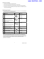
The Table below shows the available programming menu items P1 ~ P7. Each parameter
is explained in detail in the subsequent sections.
Parameters Code Selections
P1 pH buffer solution series selection
USA (Europe & U.S.A)
NIS (NIST)
CH (China)
P2
Distilled water pH temperature
compensation setting (see notes
below this Table)
OFF / ON
P3
Distilled water with Ammonia pH
temperature compensation setting
(see Notes below this Table)
OFF / ON
P4 Temperature unit setting ℃ / ℉
P5 Back light display time setting 0-1-3-6min
P6 Auto power off setting 0-10-20min
P7 Restore to default factory settings OFF / ON
Notes on P2 and P3 Parameters: Measurements of distilled water and distilled water
mixed with ammonia affect the temperature compensation and the slope linearity of the pH
probe. Such measurements are sometimes used in the electrical power and petrochemical
industries. Set these parameters to ON only if necessary, otherwise leave these
parameters in the OFF state.
www.burntec.comwww.burntec.com

EC600 V2.0 4/10
8
Parameter P1 (pH Buffer Solution Setting)
1. From the pH measurement mode, press and hold MODE for at least 2 seconds and
then release, the ‘P1’ icon appears on the LCD
2. Use the CAL or the M+/RM keys to toggle through the three (3) selections: USA (for
use in the USA or Europe, NIS (for NIST calibration purposes), and CH (for use in
China)
3. Momentarily press MODE to move to the next parameter (P2), or press ENTER to
return to the normal measurement mode
Parameter P2 (Distilled Water Temperature Compensation Setting)
1. From the P2 menu, use the CAL or the M+/RM keys to turn this feature ON or OFF
2. Momentarily press MODE to move to the next parameter (P3), or press ENTER to
return to the normal measurement mode
Parameter P3 (Distilled Water with Ammonia Temperature Compensation Setting)
1. From the P3 menu, use the CAL or the M+/RM keys to turn this feature ON or OFF
2. Momentarily press MODE to move to the next parameter (P4) or press ENTER to
return to the normal measurement mode
Parameter P4 (Temperature Measurement Units Setting)
1. From the P4 menu, use the CAL or the M+/RM keys to turn this feature ON or OFF
2. Momentarily press MODE to move to the next parameter (P5) or press ENTER to
return to the normal measurement mode
Parameter P5 (Display Backlight Setting)
1. From the P5 menu, use the CAL or the M+/RM keys to select 0, 1, 3, or 6 minute
default backlighting time
2. Momentarily press MODE to move to the next parameter (P6) or press ENTER to
return to the normal measurement mode
Parameter P6 (Automatic Power OFF Setting)
1. From the P6 menu, use the CAL or the M+/RM keys to select a 0, 10, or 20 minute
Auto Power OFF time
2. Momentarily press MODE to move to the next parameter (P7) or press ENTER to
return to the normal measurement mode
Parameter P7 (Restore Factory Default Settings)
1. From the P7 menu, use the CAL or the M+/RM keys to select ON (reset the factory
default settings) or OFF (cancel edit)
2. Momentarily press MODE to move to the first parameter (P1) or press ENTER to return
to the normal measurement mode
www.burntec.comwww.burntec.com

EC600 V2.0 4/10
9
pH Measurement, Calibration, and Electrode Considerations
• Error messages ERR-1: Electrode zero potential error and ERR-2: Electrode slope
error; For either error, check the following:
1. Air bubbles in the electrode bulb. Shake rigorously to remove air bubbles
2. Accuracy of the pH buffers used in calibration. Replace buffers if necessary
3. Set meter to its factory default state in Parameter P7 (previous section of manual)
• Calibration intervals depend on the sample, the electrode performance, and the
required accuracy. For high accuracy measurements (≤ ±0.02pH), the meter should be
calibrated immediately before taking a measurement. For general accuracy (≥±0.1pH),
the meter can be calibrated and used for approximately one week before the next
calibration.
• The meter must be recalibrated in the following situations:
1. New probe, or probe that is unused for a long period of time
2. After measuring acids (pH<2) or alkaline solutions (pH>12)
3. After measuring a solution that contains fluoride or a concentrated organic solution
4. If the solution’s temperature differs widely from the calibration solution temperature
• The soaking solution contained in the supplied protective bottle is used to maintain
activation in the glass bulb and junction. Loosen the capsule, remove the electrode and
rinse in distilled water before taking a measurement. Insert the electrode and tighten
the capsule after measurements to prevent the solution from leaking. If the soak
solution is turbid or moldy, replace the solution.
• To prepare a soak solution: Use 25g pure KCL dissolved with purified water and diluted
to 100mL. The electrode should not be soaked in a purified water protein solution or an
acid fluoride solution for long periods of time. In addition, do not soak the electrode in
organic silicon lipids.
• For calibration accuracy, the pH of the standard buffer solution must be reliable. The
buffer solution should be refreshed often, especially after heavy use.
• For best accuracy, always keep the meter clean and dry, especially the meter’s
electrode and electrode jack. Clean with medical cotton and alcohol if necessary.
• The sensitive glass bulb at the front of the combination electrode should not come in
contact with hard surfaces. Scratches or cracks on the electrode will cause inaccurate
readings. Before and after each measurement, the electrode should be washed with
distilled water and air dried. Do not clean the glass bulb with a tissue for it will affect the
stability of the electrode potential and increase the response time. The electrode
should be thoroughly cleaned if a sample sticks to the electrode. Use a solvent if the
solution does not appear clean after washing.
• Electrodes that have been used over a long period of time, used in a strong solution
that has damaged the sensitive bulb, or used with a substance resulting in a jam at the
junction will be become passivated; the sensitivity will decrease, its response will slow,
and the readings will be inaccurate. Replace the electrode as soon as possible in these
cases.
• For abnormal readings, try calibrating again; if the problem persists replace the
Electrode. The user can also try resetting the meter to factory default conditions per
Parameter P7 (detailed in an earlier section). Electrode life can be shortened by heavy
use, extreme conditions, and improper maintenance.
www.burntec.comwww.burntec.com

EC600 V2.0 4/10
10
mV Measurement Mode
1. Turn the meter ON using the power key
2. Momentarily press MODE to switch to the mV mode, if necessary
3. Connect the probe to the meter
4. Immerse the electrode in the sample solution, slowly stir the solution with the
electrode and then allow it to rest in the solution
5. When the smile face icon appears on the LCD, the reading has stabilized
mV Programming Parameters
Prompt Parameters Code Settings
P1 Back light display time
0 -1-3-6 min
P2 Auto power off time
0 -10-20 min
Parameter P1 (Display Backlight Setting)
1. Press MODE to access the P1 Parameter
2. Use the CAL or the M+/RM keys to select 0, 1, 3, or 6 minute default backlighting
time
3. Momentarily press MODE to move to the next parameter (P2) or press ENTER to
return to the normal measurement mode
Parameter P2 (Automatic Power OFF Setting)
1. From the P2 menu, use the CAL or the M+/RM keys to select a 0, 10, or 20 minute
Auto Power OFF time
2. Momentarily press MODE to move back to Parameter P1, or press ENTER to
return to the normal measurement mode
www.burntec.comwww.burntec.com

EC600 V2.0 4/10
11
Conductivity Measurement Mode
Preparation for Measurement
1. Turn the meter ON using the power key
2. Press the MODE key momentarily to switch to the Conductivity mode, if necessary
3. Use the ENTER key to select TDS (Total Dissolved Solids), Salinity, Resistivity, and
Conductivity
4. Unscrew the protective cap on the probe jack located on the bottom of the meter (store
the protective cap in the carrying case for later use)
5. Carefully connect the electrode to the meter’s input jack. The electrode can only be
inserted in one orientation. Once it is firmly connected, screw the electrode collar onto
the meter to secure it
Calibration
1. Press the CAL key and “CAL” will appear flashing on the LCD
2. Clean and air dry the conductivity electrode (use distilled water to clean)
3. Immerse the electrode in the 1413μS/cm calibration solution
4. Stir the solution with the electrode and then allow it to rest in the solution until the
stabilized icon (smile face icon) appears
5. Press CAL again and the display will flash “1413μS/cm”; After several seconds the
“END” icon will appear and the meter will return to the measuring mode
6. The LCD will display the stable measurement reading 1413μS/cm and the calibration
icon “M”, indicating that the calibration is complete.
7. If the measurement value is unstable, repeat the calibration until the measurement is
stable. Replace the electrode if necessary.
Notes: The meter is calibrated before leaving the factory and can generally be used
right out of the box. The meter can only be calibrated in the Conductivity mode and not
from the TDS, Salinity, or Resistivity mode.
Measuring the Conductivity of a Sample
1. Clean and dry the conductivity electrode and immerse in the sample solution
2. Stir the solution and then allow the electrode to rest in the solution until the reading
stabilizes (smile face icon appears)
3. Read the conductivity measurement on the meter’s display
6. Use the ENTER key to select TDS (Total Dissolved Solids), Salinity, Resistivity, and
Conductivity measurement modes
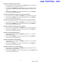
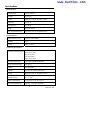
Calibration Considerations
This meter offers two calibration solution series (configured in Parameter P1).
(a) (Europe & U.S.A. series) — 84μS/cm, 1413μS/cm, 12.88 mS/cm and 111.9 mS/cm
(b) (China series) — 146.6μS/cm, 1408μS/cm, 12.85mS/cm and 111.3 mS/cm
The EC600 offers a unique one-point calibration feature. The user can select the
calibration solution closest to the expected measuremnt value. In general the most
common calibration solution is 1413 μS/cm. Use the supplied conductivity electrode (K = 1
cm
-1
), and perform the calibration using the supplied 1413 μS/cm calibration solution. The
meter can then be used for measurements below 100 mS/cm. Please refer to the chart
below.
www.burntec.comwww.burntec.com

EC600 V2.0 4/10
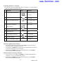
12
Measuring range 0.05 to 20μS/cm 0.5μS/cm to 200mS/cm
Electrode constant
K=0.1cm
-
1
(flow
test)
K=1.0cm
-
1
Calibration solution 84μS/cm 84μS/cm 1413μS/cm 12.88 mS/cm
111.9 mS/cm
Calibration
indicator
There are two electrode calibration methods: Standard Solution calibration and Constant
calibration. The calibration described above in the section Calibration refers to the
Standard Solution method (the most accurate calibration method, assuming the calibration
buffer standard is accurate and fresh).
To select the Constant calibration method use Parameter P5 described below in the
Programming Parameters – Conductivity section.
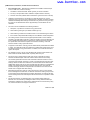
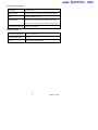
The meter’s temperature compensation coefficient is 2.0%. However, the conductivity
temperature coefficient is different for solutions of a different variety and concentration.
Use the chart below for common solution types (use Parameter P4 as described below in
the Programming Parameters – Conductivity section).
The meter can perform an automatic non-linear temperature compensation in distilled
water for measurements below 10 μS/cm.
Note: When the coefficient for the temperature compensation is set to 0.00 (no
compensation), the measurment value will be based on the current temperature.
Solution
Temperature compensation
coefficient
NaCl salt solution 2.12%
5%NaOH solution 1.72%
Diluted ammonia solution 1.88%
10% hydrochloric acid solution 1.32%
5% sulfuric acid solution 0.96%
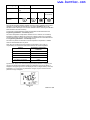
Important Note: When one or more of the programmable parameters is changed by the
user from its original factory default condition, the parameter’s code, shown below, is
displayed in the upper right corner of the display as shown in diagram below (in this case,
Parameter ‘Tcc’). If more than one parameter is changed, only the code from the first
parameter change is displayed.
www.burntec.comwww.burntec.com

EC600 V2.0 4/10
13
Programming Parameters - Conductivity
The Table below shows the available programming menu items P1 ~ P7. Each parameter
is explained in detail in the subsequent sections.
Parameters Code Selections
P1 Standard solution series selection
USA (Europe & U.S.A)
CH (China)
P2
Electrode Constant selection
0.1, 1, or 10
P3
Reference Temperature selection
77, 68, and 64
o
F (25,
20,and 18 ℃)
P4 Temperature compensation
coefficient setting
0.00 to 9.99%
P5 Electrode Constant Calibration
P6 Temperature units ℃ ℉
P7 Back light display time setting 0-1-3-6 minutes
P8 Auto power off setting 0-10-20 minutes
P9 Restore to default factory settings OFF / ON
Parameter P1 (pH Buffer Solution Setting)
1. From the pH measurement mode, press and hold MODE for at least 2 seconds and
then release, the ‘P1’ icon appears on the LCD
2. Use the CAL or the M+/RM keys to toggle through the two (2) selections: USA (for use
in the USA or Europe) and CH (for use in China)
3. Momentarily press MODE to move to the next parameter (P2), or press ENTER to
return to the normal measurement mode
Parameter P2 (Electrode Constant ‘K’ Selection)
1. From the P2 menu, use the CAL or the M+/RM keys to select the desired electrode
constant (0.1, 1.0, or 10). The default setting is K=1.0
2. Momentarily press MODE to move to the next parameter (P3), or press ENTER to
return to the normal measurement mode
www.burntec.comwww.burntec.com

EC600 V2.0 4/10
14
Parameter P3 (Reference Temperature Selection)
1. From the P3 menu, use the CAL or the M+/RM keys to select the desired reference
temperature (25, 20, or 18℃).The default setting is 25℃
2. Momentarily press MODE to move to the next parameter (P4) or press ENTER to
return to the normal measurement mode
Parameter P4 (Temperature Coefficient Temperature Compensation Setting)
1. From the P4 menu, use the CAL or the M+/RM keys to select the coefficient in percent
from 0.00 to 9.99. When set to zero, the temperature compensation is turned OFF. The
default setting is 2.0%
2. Momentarily press MODE to move to the next parameter (P5) or press ENTER to
return to the normal measurement mode
Parameter P5 (Electrode Constant calibration)
1. In the P5 window the user can see the existing constant in the main measurement area
of the LCD in cm
-1
units
2. From the P5 menu, use the CAL or the M+/RM keys to change the constant to match
the constant printed on the electrode housing
3. Momentarily press MODE to move to the next parameter (P6) or press ENTER to
return to the normal measurement mode
Parameter P6 (Temperature units of measure)
1. From the P6 menu, use the CAL or the M+/RM keys to select the desired unit of
measure (C or F)
2. Momentarily press MODE to move to the next parameter (P7) or press ENTER to
return to the normal measurement mode
Parameter P7 (Display Backlight Setting)
1. From the P7 menu, use the CAL or the M+/RM keys to select 0, 1, 3, or 6 minute
default backlighting time
2. Momentarily press MODE to move to the next parameter (P8) or press ENTER to
return to the normal measurement mode
Parameter P8 (Automatic Power OFF Setting)
1. From the P8 menu, use the CAL or the M+/RM keys to select a 0, 10, or 20 minute
Auto Power OFF time
2. Momentarily press MODE to move to the next parameter (P9) or press ENTER to
return to the normal measurement mode
Parameter P9 (Restore Factory Default Settings)
1. From the P9 menu, use the CAL or the M+/RM keys to select ON (reset the factory
default settings) or OFF (cancel edit); Note that by selecting ON the factory default
settings will automatically switch ON, there is no confirmation step. The user should
select ON only if absolutely certain that the default settings be accessed.
2. Momentarily press MODE to move to the first parameter (P1) or press ENTER to return
to the normal measurement mode
www.burntec.comwww.burntec.com

EC600 V2.0 4/10
15
Conductivity Measurement, Calibration, and Maintenance Considerations
• The meter and probe are calibrated before leaving the factory; the user can take
measurements immediately upon receiving the unit
• The recommend calibration period is once per month under normal circumstances; It is
necessary to calibrate a newly purchased conductivity electrode or one that has been
in service for a long period of time
• Keep the conductivity electrode clean. It’s best to rinse electrodes with distilled water
and air dry
• The surface of the supplied conductivity electrode is plated with a layer of metal
platinum (black) in order to lower the electrode polarization and increase the measuring
range. Do not polish the black platinum surface; clean it by stirring in Distilled water. If
excessive organic buildup appears on the black platinum coating clean with hot water
and detergent or with alcohol
• Replace the electrode if the above cleaning methods are ineffective
• Reset the meter to its factory default settings (Parameter P9) if unusual operation is
noticed. If the restore process does not solve the issue, return the unit for an evaluation
www.burntec.comwww.burntec.com

EC600 V2.0 4/10
16
Specifications
pH Specifications
Measuring range -2.00 to 19.99 pH
Resolution 0.1/0.01 pH
Accuracy Meter only: ±0.01pH; with probe: ±0.02pH
Input current ≤ 2×10
-12
A
Input impedance ≥ 1×10
12
Ω
Stability ±0.01 pH / 3hours
Temp. Compensation range 32 to 212
o
F (0 to 100 ℃) automatic (ATC)
mV Specifications
Measuring range (mV/E
H
) -1999 mV to 0 to 1999mV
Resolution 1mV
Accuracy Meter: ±0.1% FS
Conductivity Specifications
Conductivity measuring ranges
0.00 to 19.99 µS/cm
20.0 to 199.9 µS/cm
200 to 1999 µS/cm
2.00 19.99 mS/cm
20.0 to 199.9 mS/cm
TDS measurement range 0 to 100 g/L (Total Dissolved Solids)
Salinity measurement range 0 to 100 ppt
Resistivity 0 to 100 Mohms
Resolution 0.01/0.1/1 µS/cm and 0.01/0.1mS/cm
Accuracy Meter only: ±1% F.S.; with probe: ±2% F.S.
Electrode constant 0.1 / 1 / 10 cm
-1
Reference temperatures 77, 68, and 64
o
F (25, 20,and 18 ℃)
Temp. Compensation range 32 to 122
o
F (0 to 50 ℃) (automatic)
www.burntec.comwww.burntec.com

EC600 V2.0 4/10
17
Other Technical Parameters
Data storage 300 data groups
Storage content Data serial number, measurement value, unit of measure
Power Two ‘AA’ batteries (1.5V x 2)
Size and weight Meter: 2.6 x 4.7 x 1.2” (65 × 120 × 31mm) / 6.3 oz (180g)
Case: 14.1 x 10.6 x 3” (360 x 270 x 76mm) / 3.57 lbs (1.7kg)
Quality/Safety certification ISO9001, CE and CMC
Working Conditions
Environment temperature 41 to 95
o
F (5 to 35 ℃)
Environmental humidity ≤ 85%
IP rating IP57 Dustproof and waterproof
www.burntec.comwww.burntec.com

EC600 V2.0 4/10
18
Support line (781) 890-7440
Technical Support: Extension 200; E-mail: supp[email protected]
Repair & Returns: Extension 210; E-mail: repair@extech.com
Product specifications subject to change without notice
For the latest version of this User Guide, Software updates, and other
up-to-the-minute product information, visit our website: www.extech.com
Extech Instruments Corporation, 285 Bear Hill Road, Waltham, MA 02451
ISO9001 Certified
Warranty
EXTECH INSTRUMENTS CORPORATION (A FLIR COMPANY) warrants this instrument to be free of
defects in parts and workmanship for one year from date of shipment (a six month limited warranty
applies to sensors and cables). If it should become necessary to return the instrument for service during
or beyond the warranty period, contact the Customer Service Department at (781) 890-7440 ext. 210 for
authorization or visit our website www.extech.com for contact information. A Return Authorization (RA)
number must be issued before any product is returned to Extech. The sender is responsible for shipping
charges, freight, insurance and proper packaging to prevent damage in transit. This warranty does not
apply to defects resulting from action of the user such as misuse, improper wiring, operation outside of
specification, improper maintenance or repair, or unauthorized modification. Extech specifically
disclaims any implied warranties or merchantability or fitness for a specific purpose and will not be liable
for any direct, indirect, incidental or consequential damages. Extech's total liability is limited to repair or
replacement of the product. The warranty set forth above is inclusive and no other warranty, whether
written or oral, is expressed or implied.
Calibration and Repair Services
Extech offers repair and calibration services for the products we sell. Extech also
provides NIST certification for most products. Call the Customer Care Department for
information on calibration services available for this product. Extech recommends that
annual calibrations be performed to verify meter performance and accuracy.
Copyright © 2009 Extech Instruments Corporation (a FLIR company)
All rights reserved including the right of reproduction in whole or in part in any form.
www.burntec.comwww.burntec.com
-
 1
1
-
 2
2
-
 3
3
-
 4
4
-
 5
5
-
 6
6
-
 7
7
-
 8
8
-
 9
9
-
 10
10
-
 11
11
-
 12
12
-
 13
13
-
 14
14
-
 15
15
-
 16
16
-
 17
17
-
 18
18


Extech Instruments EC600 User manual
- Category
- Measuring, testing & control
- Type
- User manual
- This manual is also suitable for
Ask a question and I''ll find the answer in the document
Finding information in a document is now easier with AI
Related papers
-
Extech Instruments EC600 User manual
-
Extech Instruments DO700 User manual
-
Extech Instruments PH220 User manual
-
-
-
-
-
-
-
Extech Instruments EC170 User manual
Other documents
-
Lovibond Single Method SD 70 - Conductivity User manual
-
 Cole-Parmer P100 pH Meter User manual
-
-
 M & I Instruments 8218 User manual
-
Omega PHH-152 Owner's manual
-
 HM Digital HMDPHM80 User manual
-
 Hach H170 User manual
-
BANTE 520 User manual
-
Apera PH850 User manual
-
Apera Instruments PC850 User manual


