Page is loading ...

W70G-EL900XQ1 Page 1
Installation Guide
EL900 Series | Hardened Media Converter
Copyright 2023 EtherWAN Systems, Inc. All Rights Reserved 03/07/2023
1 Unpacking
Open the carton and unpack the items. Your package
should include an EL1142 media converter and an AC
to DC power adaptor and cable
(optional). If items are missing or
damaged, notify your EtherWAN
representative.
Download the full manual at:
https://www.etherwan.com
2 Select Installation Location
Installation is DIN rail-mount, or wall mount (in an
enclosure or industrial panel). Ensure that the power
source is within 6 feet (1.8 meters), and check that
there is adequate airflow. Operating temperature
range is -40to 75°C (-40 to 167°F).
3 Connect Power
DC Terminal Block Power Inputs: There are two
10~48VDC power inputs that can be used to power
up this device.
Only one power input is required to run the media
converter, but with only one power connection the
FAULT LED indicator will light up to indicate
abnormality in the power redundancy system. The
media converter will work normally even if the fault
LED indicator lights up.
DC Jack Power input: 12VDC.
Terminal Block
DC Jack
Note: Use qualified power supply by SELV or
double insulation of UL 60950 or UL 61010-1 or UL
61010-2-201 standards.
Insert the DC input wires into the corresponding
terminals, and tighten the clamp screws to hold them
in place. Make sure that the plastic terminal block
connector prongs are plugged firmly into the terminal
block receptacles.
Power wiring information:
Use cable type - AWG (American Wire Gauge) 18-24
and the corresponding pin type cable terminals.
Use torque value 1.7 lb-in, do not use excessive force
when fixing wiring.
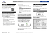
4 Front Panel Reference
Pin
Description
PW1
10-48VDC
GND
Power Ground
PW2
10-48VDC
GND
Power Ground
Earth Ground
The relay contact opens if
Power 1 or Power 2 fails.
The relay contact opens if port
link fails (When Link Down
Detection is enabled).
Pin
Description
PW1
Power input 3A@12VDC
GND
Power Ground
The relay contact opens if
Power 1 or Power 2 fails.
The relay contact opens if port
link fails (When Link Down
Detection is enabled).

W70G-EL900XQ1 Page 2
Installation Guide
EL900 Series | Hardened Media Converter
Copyright 2023 EtherWAN Systems, Inc. All Rights Reserved 03/07/2023
5 LED Indicators
LEDs
State
Indication
FAULT
Steady
Power redundant system or ports
function abnormal
Off
Power redundant system and ports
function normally
PWR1
PWR2
Steady
Power on
Off
Power off
100
(Mbps)
Steady
Connection at the speed of
100Mbps
Off
Connection at the speed of
10Mbps
LFP
Steady
LFPT function enabled
Off
LFPT function disabled
LNK/ACT
Steady
Valid network connection
established
Flashing
Transmitting or receiving data
Off
Neither valid network connection
established nor transmitting /
receiving data
FDX/COL
Steady
Connection in full duplex mode
Flashing
Collision occurred
Off
Connection in half-duplex mode
6 DIP Switch Settings
Port, power and LFPT settings are made very simple by
means of DIP (Dual Inline Package) switches on the
bottom panel of the hardened media converter.
* LFPT=Link Fault Pass Through
Link-Fault-Pass-Through allows network operators to
stay aware of network connection status. If a link fails,
the function will disable the link on the other side,
therefore notifying the connected device of the link
failure.
If Force mode is enabled, the media converter must be
restarted in order for the new setting to take effect.
Pin 2 must be toggled to position 1 prior to speed and
duplex mode manual setting.
7 Relay Output Alarm
The media converter is equipped with relay output
contacts on the terminal block for signaling of a
power or port failure. The relay output can be
connected to an alarm signaling device. Current is
0.6A @ 30VDC. Do not connect a power source to
the relay output.
8 Other Information
DIN-Rail Assembly Startup, and Dismantling
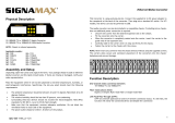
▪ Assembly: Place the device on the DIN rail from
above using the slot. Push the front of the device
toward the mounting surface until it audibly snaps
into place.
▪ Startup: Connect the supply voltage to start up
the device via the terminal block.
▪ Dismantling: Pull out the lower edge and then
remove the device from the DIN rail.
Manufacturer information:
EtherWAN Systems, Inc.
33F, No. 93, Sec. 1, Xintai 5th Rd., Xizhi Dist., New
Taipei City, 221 Taiwan
No.
0
1
1
Disable LFPT*
Enable LFPT*
2
Enable auto
negotiation for TX
port
Enable forced mode
for TX port
3
TX port forced to
100Mbps
TX port forced to
10Mbps
4
TX port forced to
full duplex mode
TX port forced to half
duplex mode
5
FX port forced to full
duplex mode
FX port forced to half
duplex mode
6
Disable link down
alarm
Enable link down
alarm
The full product manual can be downloaded from:
www.etherwan.com
/


