Page is loading ...

H3C UniServer T1100 G3 Server
User Guide
New H3C Technologies Co., Ltd.
http://www.h3c.com
Document version: 5W100- 20180509

Copyright © 2018, New H3C Technologies Co., Ltd. and its licensors
All rights reserved
No part of this manual may be reproduced or transmitted in any form or by any means without prior written
consent of New H3C Technologies Co., Ltd.
Trademarks
H3C, , H3CS, H3CIE, H3CNE, Aolynk, , H
3
Care, , IRF, NetPilot, Netflow, SecEngine,
SecPath, SecCenter, SecBlade, Comware, ITCMM and HUASAN are trademarks of New H3C Technologies
Co., Ltd.
All other trademarks that may be mentioned in this manual are the property of their respective owners.
Notice
The information in this document is subject to change without notice. All contents in this document, including
statements, information, and recommendations, are believed to be accurate, but they are presented without
warranty of any kind, express or implied. H3C shall not be liable for technical or editorial errors or omissions
contained herein.
Environmental protection
This product has been designed to comply with the environmental protection requirements. The storage, use,
and disposal of this product must meet the applicable national laws and regulations.

Preface
This preface includes the following topics about the documentation:
• Audience.
• Conventions.
• Documentation feedback.
Audience
This documentation is intended for:
• Network planners.
• Field technical support and servicing engineers.
• Server administrators working with the T1100 G3 Server.
Conventions
The following information describes the conventions used in the documentation.
Command conventions
Convention Description
Boldface Bold
text represents commands and keywords that you enter literally as shown.
Italic
Italic text represents arguments that you replace with actual values.
[ ] Square brackets enclose syntax choices (keywords or arguments) that are optional.
{ x | y | ... }
Braces enclose a set of required syntax choices separated by vertical bars, from which
you select one.
[ x | y | ... ]
Square brackets enclose a set of optional syntax choices separated by vertical bars,
from which you select one or none.
{ x | y | ... } *
Asterisk marked braces enclose a set of required syntax choices separated by vertical
bars, from which you select a minimum of one.
[ x | y | ... ] *
Asterisk marked square brackets enclose optional syntax choices separated by vertical
bars, from which you select one choice, multiple choices, or none.
&<1-n>
The argument or keyword and argument combination before the ampersand (&) sign
can be entered 1 to n times.
# A line that starts with a pound (#) sign is comments.
GUI conventions
Convention Description
Boldface
Window names, button names, field names, and menu items are in Boldface. For
example, the
New User
window opens; click
OK
.
>
Multi-level menus are separated by angle brackets. For example,
File
>
Create
>
Folder
.

Symbols
Convention Description
WARNING!
An alert that calls attention to important information that if not understood or followed
can result in personal injury.
CAUTION:
An alert that calls attention to important information that if not understood or followed
can result in data loss, data corruption, or damage to hardware or software.
IMPORTANT:
An alert that calls attention to essential information.
NOTE:
An alert that contains additional or supplementary information.
TIP:
An alert that provides helpful information.
Network topology icons
Convention Description
Represents a generic network device, such as a router, switch, or firewall.
Represents a routing-capable device, such as a router or Layer 3 switch.
Represents a generic switch, such as a Layer 2 or Layer 3 switch, or a router that
supports Layer 2 forwarding and other Layer 2 features.
Represents an access controller, a unified wired-WLAN module, or the access
controller engine on a unified wired-WLAN switch.
Represents an access point.
Represents a wireless terminator unit.
Represents a wireless terminator.
Represents a mesh access point.
Represents omnidirectional signals.
Represents directional signals.
Represents a security product, such as a firewall, UTM, multiservice security
gateway, or load balancing device.
Represents a security module, such as a firewall, load balancing, NetStream, SSL
VPN, IPS, or ACG module.
Examples provided in this document
Examples in this document might use devices that differ from your device in hardware model,
configuration, or software version. It is normal that the port numbers, sample output, screenshots,
and other information in the examples differ from what you have on your device.
T
T
T
T

Documentation feedback
You can e-mail your comments about product documentation to info@h3c.com.
We appreciate your comments.

i
Contents
Safety information ············································································ 1
General operating safety ············································································································· 1
Electrical safety ························································································································· 1
ESD prevention ························································································································· 1
Preventing electrostaic discharge ··························································································· 1
Grounding methods to prevent electrostatic discharge ································································· 2
Cooling performance ·················································································································· 2
Battery safety ···························································································································· 2
Connecting external cables ································································ 3
Connecting monitors ··················································································································· 3
Connecting the VGA connector to a monitor ·············································································· 3
Connecting a DP connector to a monitor ·················································································· 3
Connecting an Ethernet cable ······································································································· 4
Connecting the power cord ·········································································································· 5
Guidelines ························································································································· 5
Procedure ·························································································································· 5
Powering on and powering off the server ··············································· 7
Powering on the server ··············································································································· 7
Prerequisites ······················································································································ 7
Procedure ·························································································································· 7
Powering off the server ··············································································································· 7
Guidelines ························································································································· 7
Procedure ·························································································································· 7
Installing hardware options ································································· 8
Installing drives ························································································································· 8
Guidelines ························································································································· 8
Preparing for drive installation ································································································ 8
Install a drive in the drive cage ····························································································· 10
Installing a drive at the chassis bottom ··················································································· 11
Completing drive installation ································································································ 11
Verifying the installation ······································································································ 13
Installing DIMMs ······················································································································ 14
Guidelines ······················································································································· 14
Procedure ························································································································ 14
Verifying the installation ······································································································ 15
Installing a storage controller ······································································································ 15
Guidelines ······················································································································· 15
Procedure ························································································································ 16
Installing a GPU module ············································································································ 19
Guidelines ······················································································································· 19
Procedure ························································································································ 19
Installing Ethernet adapters ········································································································ 20
Guidelines ······················································································································· 20
Procedure ························································································································ 20
Installing an optical drive ··········································································································· 21
Connecting internal cables ······························································· 23
Connecting drive cables ············································································································ 23
Connecting drive power cords ······························································································ 23
Connecting drive data cables ······························································································· 24
Connecting optical drive cables ··································································································· 25
Connecting the optical drive power cord ················································································· 25
Connecting the optical drive data cable ·················································································· 26

ii
Appendix A Server specifications ······················································ 27
Overview ································································································································ 27
Specifications ·························································································································· 27
Components ··························································································································· 29
Front panel ····························································································································· 30
Front panel components ····································································································· 30
LEDs and buttons ·············································································································· 31
Ports······························································································································· 31
Rear panel ····························································································································· 32
Rear panel component ······································································································· 32
LEDs ······························································································································ 33
Ports······························································································································· 33
System board ·························································································································· 35
System board components ·································································································· 35
Clear CMOS jumper ··········································································································· 35
DIMM slots ······················································································································· 36
Appendix B Component specifications ··············································· 37
Processors ····························································································································· 37
Processor specifications ····································································································· 37
DIMMs ··································································································································· 37
DIMM specifications ··········································································································· 37
DIMM rank classification label ······························································································ 37
Drives ···································································································································· 38
Drive specifications ············································································································ 38
Drive numbering ················································································································ 39
PCIe modules ························································································································· 39
Storage controllers ············································································································ 39
GPU modules ··················································································································· 40
Ethernet adapters ·············································································································· 40
Power supplies ························································································································ 41
Power supply specifications ································································································· 41
Optical drives ·························································································································· 41
Optical drive specifications ·································································································· 41
Fans ····································································································································· 41
Appendix C Product recycling ·························································· 43
Appendix D Glossary ····································································· 44
Appendix E Acronyms ···································································· 45

1
Safety information
To avoid bodily injury or damage to the server, read the following information carefully before you
operate the server.
General operating safety
To avoid bodily injury or damage to the server, follow these guidelines when you operate the server:
• Only H3C authorized or professional server engineers are allowed to install, service, repair,
operate, or upgrade the server.
• Place the server on a clean, stable workbench or floor for servicing.
• Make sure all cables are correctly connected before you power on the server.
• To avoid being burnt, allow the server and its internal modules to cool before touching them.
Electrical safety
WARNING!
If you put the server in standby mode (system LED in amber) with the power on/off button on the
front panel, the power supplies continue to supply power to some circuits in the server. To remove all
power for servicing safety, you must first press the button until the system enters standby mode, and
then remove all power cords from the server.
To avoid bodily injury or damage to the server, follow these guidelines:
• Always use the power cords that came with the server.
• Do not use the power cords that came with the server for any other devices.
• Power off the server when installing or removing any components that are not hot swappable.
ESD prevention
Electrostatic charges that build up on people and tools might damage or shorten the lifespan of the
system board and electrostatic-sensitive components.
Preventing electrostaic discharge
To prevent electrostatic damage, follow these guidelines:
• Transport or store the server with the components in antistatic bags.
• Keep the electrostatic-sensitive components in separate antistatic bags until they arrive at an
ESD-protected area.
• Place the components on a grounded surface before removing them from their antistatic bags.
• Avoid touching pins, leads, or circuitry.
• Make sure you are reliably grounded when touching an electrostatic-sensitive component or
assembly.

2
Grounding methods to prevent electrostatic discharge
The following are grounding methods that you can use to prevent electrostatic discharge:
• Wear an ESD wrist strap and make sure it makes good skin contact and is reliably grounded.
• Take adequate personal grounding measures, including wearing antistatic clothing and static
dissipative shoes.
• Use conductive field service tools.
• Use a portable field service kit with a folding static-dissipating work mat.
Cooling performance
Poor cooling performance might result from improper airflow and poor ventilation and cause damage
to the server.
To ensure good ventilation and proper airflow, follow these guidelines:
• Install blanks if the PCIe slots are empty.
• Do not block the ventilation openings in the server chassis.
• To avoid thermal damage to the server, do not operate the server for long periods in any of the
following conditions:
{ Access panel open or uninstalled.
{ PCIe slots empty.
Battery safety
The server's system board contains a system battery, which is designed with a lifespan of 5 to 10
years.
If the server no longer automatically displays the correct date and time, you might need to replace
the battery. When you replace the battery, follow these safety guidelines:
• Do not attempt to recharge the battery.
• Do not expose the battery to a temperature higher than 60°C (140°F).
• Do not disassemble, crush, puncture, short external contacts, or dispose of the battery in fire or
water.
• Dispose of the battery at a designated facility. Do not throw the battery away together with other
wastes.

3
Connecting external cables
Connecting monitors
The server provides one DB15 VGA connector and two DP connectors on the rear panel for
connecting monitors.
• When DOS is used for interacting with the operating system, only one monitor will have a
correct display if you connect more than one monitor to the server. The connectors are in the
following order of precedence for correct display: DP connect 2 > DP connector 1 > VGA
connector.
• When shell is used for interacting with the operating system, the monitor connected to DP 1
connector will not have a correct display if you connect three monitors to the server. If you
connect less than three monitors to the server, all the monitors will have a correct display.
For more information about DOS and shell, see the BIOS user guide for the server.
Connecting the VGA connector to a monitor
1. Connect one plug of a VGA cable to the VGA connector on the server, and fasten the screws on
the plug.
Figure 1 Connecting the VGA connector
2. Connect the other plug of the VGA cable to the VGA connector on the monitor, and fasten the
screws on the plug.
Connecting a DP connector to a monitor
As shown in Figure 2, connect one plug of the DP cable to a DP connector on the server and the
other plug of the DP cable to the DP connector on the monitor.

4
Figure 2 Connecting a DP connector
Connecting an Ethernet cable
1. Make sure the Ethernet cable type is as required.
If you are replacing an Ethernet cable, make sure the new cable is the same type as the old
cable.
2. Verify the connectivity of the cable by using an Ethernet cable tester.
3. Label the Ethernet cable by filling in the names and numbers of the server and the peer device
on the label.
As a best practice, use labels of the same kind for all cables.
If you are replacing the Ethernet cable, label the new cable with the same number as the old
cable.
4. Connect one end of the Ethernet cable to the Ethernet port on the server and the other end to
the peer device.

5
Figure 3 Connecting an Ethernet cable
5. Verify network connectivity.
After powering on the server, use a ping command to test the network connectivity. If the peer
device is not reachable, verify that the Ethernet cable is correctly connected.
Connecting the power cord
Guidelines
WARNING!
To avoid bodily injury and device damage, use the power cord that came with the server.
Before connecting the power cord, make sure the server and components are installed correctly.
Procedure
1. Insert one end of the power cord into the power receptacle on the rear panel, as shown
in Figure 4.

6
Figure 4 Connecting the power cord to the server
2. Connect the other end of the power cord to a power source, for example, a power strip on the
rack.

7
Powering on and powering off the server
Powering on the server
Prerequisites
Before powering on the server, you must complete the following tasks:
• Install the server and internal components correctly.
• Connect the server to a power source.
Procedure
Press the power on/off button on the front panel to power on the server. The server exits standby
mode and the power source supplies power to the server.
The system power LED is steady green when the server is being powered correctly. For the system
power LED location, see LEDs and buttons on the front panel in "Appendix A Server specifications."
Powering off the server
Guidelines
Before powering off the server, you must complete the following tasks:
• Back up all data.
• Make sure all services have been stopped or have been migrated to other servers.
Procedure
Powering off the server from its operating system
1. Connect a monitor, mouse, and keyboard to the server.
2. Shut down the operating system of the server.
3. Disconnect the power cord from the server.
Powering off the server by pressing the power on/off button
1. Press and hold the power on/off button for a minimum of 5 seconds.
This method forces the server to enter standby mode without properly exiting applications and
the operating system. If an application stops responding, you can use this method to force a
shutdown.
2. Disconnect the power cord from the server.

8
Installing hardware options
If you are installing multiple hardware options, read their installation procedures and identify similar
steps to streamline the entire installation procedure.
Installing drives
Guidelines
Follow these guidelines to install drives for the server:
• You can install a maximum of five drives for the server.
• The drives are not hot swappable.
• Install drives starting from drive bay 1, in ascending order of drive bay IDs. For drive bay
locations and IDs, see drive numbering in "Appendix B Component specifications."
• If you are usi
ng the drives to create a RAID, follow these restrictions and guidelines:
{ To build a RAID (or a logical drive) successfully, make sure all drives in the RAID are HDDs
and use SATA connectors.
{ For efficient use of storage, use drives that have the same capacity to build a RAID. If the
drives have different capacities, the lowest capacity is used across all drives in the RAID.
{ As a best practice, use drives that do not contain RAID information to build a RAID.
• To install drives in drive bays 3, 4, and 5, use a 3-way SATA power cord for the drives. For drive
bay locations and IDs, see drive numbering in "Appendix B Component specifications."
Preparing for drive installation
1. Power off the server. For more information, see "Powering off the server."
2. Lay the server on its side.
3. Remove the access panel.
a. As shown by callout 1 in Figure 5, remo
ve the thumbscrews from the access panel.
b. As shown by callouts 2 and 3 in Figure 5, hold the ha
ndle on the access panel to pull the
access panel to the rear of the chassis and then remove it.

9
Figure 5 Removing the access panel
4. Place the server with the top side facing up.
5. Remove the security bezel from the server.
a. As shown by callout 1 in Figure 6, op
en the three retaining tabs on the security bezel.
Figure 6 Opening the three retaining tabs on the security bezel
b. As shown by callouts 2 and 3 in Figure 7, turn the security bezel counterclockwise and
remove it.

10
Figure 7 Removing the security bezel
6. Remove the drive cage shield. As shown in Figure 8, remove the screws that secure the shield
to the chassis and then take the shield away from the chassis.
Figure 8 Removing the drive cage shield
Install a drive in the drive cage
1. As shown by callout 1 in Figure 9, orient the drive with the label facing up. Slide the drive into
the target drive bay in the drive cage.
The drives came with rails. To install a drive in the drive cage, do not remove the rails from the
drive.
2. As shown by callout 2 in Figure 9, use scre
ws to secure the drive in the drive bay from the cage
side.
3. Connect the power cord and data cable for the drive. For more information, see "Connecting
drive ca
bles."

11
Figure 9 Installing a drive in the drive cage
Installing a drive at the chassis bottom
1. Place the server on its side.
2. Remove the drive rails from the drive.
3. Align the screw holes in the bottom of the drive with the four HDD screw holes and use screws
to secure the drive to the chassis bottom.
Figure 10 Installing a drive at the chassis bottom
4. Connect the power cord and data cable for the drive. For more information, see "Connecting
drive cables."
Completing drive installation
1. Install the drive cage shield. As shown in Figure 11, align the four screw holes in the drive cage
shield with the screw holes in the cage and use screws to secure the shield to the cage.

12
Figure 11 Installing the drive cage shield
2. Install the security bezel.
a. As shown by callouts 1 and 2 in Figure 12, inse
rt the three hooks on the right edge of the
bezel into the three holes in the chassis and then rotate the left side of the bezel to the
chassis.
Figure 12 Attaching the right edge of the security bezel to the chassis
b. Make sure the three retaining tabs on the left edge of the bezel snap into place on the
chassis.

13
Figure 13 Attaching the left edge of the security bezel to the chassis
3. Install the access panel.
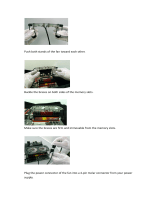
a. As shown by callouts 1 and 2 in Figure 14, lay the se
rver on its side. Place the access panel
on the server. Slide the access panel toward the front of the server.
b. As shown by callout 3 in Figure 14, use t
humbscrews to secure the access panel to the
chassis.
Figure 14 Installing the access panel
4. Connecting the power cord for the server. For more information, see "Connecting the power
cord."
5. Power on the server. For more information, see "Powering on the server."
Verifying the installation
Use the following methods to verify that the drive is installed correctly:
/