630F

DMP Electronics 630F Installation And Programming Manual

  • Hello! I am an AI chatbot trained to assist you with the DMP Electronics 630F Installation And Programming Manual. I’ve already reviewed the document and can help you find the information you need or explain it in simple terms. Just ask your questions, and providing more details will help me assist you more effectively!
POWER
TROUBLE
ALARM
COMMAND
1234
5678
90
ABC DEF GHI JKL
MNOPQR STUVWX
YX
ENABLE
SILENCE
RESET
TEST
DRILL
Fire Command Center
INSTALLATION AND PROGRAMMING GUIDE
630F Remote Fire
Command Center
About the 630F .....................................................1
Four Function Keys .............................................................1
Status LEDs ............................................................................ 1
Keyswitch ................................................................................ 1
Install the 630F ..................................................... 2
Mount the Backbox ............................................................2
Mount and Wire the Membrane Backplate ...............4
Mount the Trim Frame ......................................................4
Command Center operation ............................... 6
Command Center Operation ..........................................6
Programming ........................................................................6
Device Setup ........................................................................6
Device Number ....................................................................6
Device Name ........................................................................7
Device Type ..........................................................................7
Stop ..........................................................................................7
End-User Options ............................................... 10
Backlighting Brightness .................................................10
Internal Speaker Tone .....................................................10
Internal Volume Level ...................................................... 11
Model Number .................................................................... 11
Keypad Address ................................................................. 11
Entering Alpha Characters ................................. 12
Entering Non-Alphanumeric Characters ..........13
TABLE OF CONTENTS
Installer Options Menu........................................14
Access the User Menu.....................................................14
Programming Keypad Options .................................... 14
Keypad Options (KPD OPT) ......................................... 14
Keypad Address ............................................................... 15
Keypad Mode .................................................................... 15
Default Keypad Message .............................................. 16
Arm Panic Keys ................................................................16
Stop ...................................................................................... 16
Access Keypad Diagnostics .......................................... 17
Keypad Diagnostics (KPD OPT) ................................. 17
Stop ...................................................................................... 17
Exit the Installer Options ............................................... 18
Keypad Bus Wiring Specifications ....................19
630F Specifications ...........................................20
Compatibility .......................................................21
Certifications ....................................................... 22
California State Fire Marshal (CSFM) ....................... 22
FCC Part 15 ......................................................................... 22
New York City (FDNY COA #6167) ........................... 22
Underwriters Laboratory (UL Listed) ...................... 22
POWER
TROUBLE
ALARM
COMMAND
1234
5678
90
ABC DEF GHI JKL
MNOPQR STUVWX
YX
ENABLE
SILENCE
RESET
TEST
DRILL
Fire Command Center
Figure 1: 630F Remote Fire Command Center
Digital Monitoring Products, Inc. | 630F Installation and Programming Guide 1
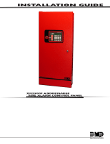
The 630F Remote Fire Command Center is a 20-key remote fire annunciator with a
32-character LCD display that can be either flush or surface mounted.
Four Function Keys
The 630F includes four function keys
allowing the user to easily silence, reset,
test, and fire drill XR150/XR550 Series
panels.
Status LEDs
The 630F provides three LEDs that indicate
system status.
Keyswitch
An added 630F feature is a keyswitch that
enables and disables the four function keys.
In order for the function keys to operate,
the factory-installed keyswitch must be
enabled. These functions and options can
also be accessed through the User Menu if
desired.
ABOUT THE 630F
2 630F Installation and Programming Guide | Digital Monitoring Products, Inc.
INSTALL THE 630F
Mount the Backbox
The 630F can either be surface mounted or flush mounted to the wall. The 630F is
comprised of three major parts: the backbox (standard or optional surface mount
635), the annunciator membrane backplate, and the trim frame. Refer to Figure 2 as
needed.
Flush Mount the Backbox
Use four 1” screws and the mounting holes on one side of the flush mount backbox
to attach the backbox to a stud. The backbox tab flush-mounts against the stud. See
Figure 2.
For post-sheetrock installation, the flush mount backbox should be mounted flush
against the sheetrock and then attached to the stud behind using the flush mounting
holes.
Surface Mount the Backbox
The optional 635 Low-Profile Backbox can be used for surface mount applications.
Use four 1” screws to attach the backbox to the wall and screw one screw in each of
the four surface mounting holes in the back of the box.
Note: The 4-hole pattern in the surface mount backbox also fits a 4” square
electrical box to allow mounting on an electrical box.
1
Digital Monitoring Products, Inc. | 630F Installation and Programming Guide 3
Slotted Screw Holes (4)
Use 3/8” Countersunk Phillips Screws
to Fasten to Backbox Screw Holes
Screw Holes (4)
Screw Holes (4)
Use 3/8” Black Phillips Screws
to Fasten to Backplate Screw Holes
Screw Holes (4)
Backbox
Stud
Membrane Backplate
Trim Frame
Surface Mounting Holes (4)
Use to Surface Mount to Wall
Knockout
Tab
Flush Mounting Holes (4)
Use to Flush Mount to Stud
1. Mount the Backbox 2. Mount the Membrane Backplate
3. Mount the Trim Frame
Figure 2: Mounting Diagram
4 630F Installation and Programming Guide | Digital Monitoring Products, Inc.
Mount and Wire the Membrane Backplate
Refer to Figure 2 for locations of knockouts on backbox for running wires and screw
holes on backbox and backplate.
1. Connect a four conductor wire from the 630F backplate terminal strip to
panel terminals 7, 8, 9, and 10. See Figure 3.
2. Attach the annunciator membrane backplate (slotted screw holes) to the
backbox using the four supplied countersunk 3/8” Phillips screws.
3. Adjust the mounting plate to the right or left so the LCD display is level.
The four slotted screw holes in the mounting plate corners allow for this
adjustment.
2
Mount the Trim Frame
Attach the trim frame to the mounting plate using the four supplied 3/8” black
Phillips screws. See Figure 2.
3
Digital Monitoring Products, Inc. | 630F Installation and Programming Guide 5
Back of Membrane Backplate
4 Position
Terminal Strip
4-Pin
Header
Pre-wired
Keyswitch
Black to 10
Green to 9
Yellow to 8
Red to 7
Figure 3: Harness Wiring Diagram
6 630F Installation and Programming Guide | Digital Monitoring Products, Inc.
COMMAND CENTER OPERATION
Command Center Operation
INTERNAL SPEAKER OPERATIONThe speaker emits standard tones for key
presses and system alerts and distinct fire siren tones during an alarm.
LCD BACKLIGHTING—lights to maximum brightness anytime a key is pressed or
the speaker sounds.
Programming
After completing each of the following steps, press CMD to advance to the next option.
Programming
Reset the panel and enter 6653 (PROG) at a keypad.
Device Setup
Go to DEVICE SETUP.
Device Number
At DEVICE NO, enter a device number.
For Keypad Bus connections, select a device number from 1-8
for XR150 panels or 1-16 for XR550 panels.
PROGRAMMER
DEVICE SETUP
DEVICE SETUP
DEVICE NO: -
Digital Monitoring Products, Inc. | 630F Installation and Programming Guide 7
Device Name
At *UNUSED*, enter the device name.
Device Type
At TYPE, select FI (Fire).
Stop
Press CMD until STOP displays. Press a top row select key or
area to save programming.
DEVICE SETUP
* UNUSED *
DEVICE SETUP
DOOR KPD FI EXP
STOP
If necessary, see the XR150/XR550 Programming Guide (LT-1232) for more information on
programming devices.
8 630F Installation and Programming Guide | Digital Monitoring Products, Inc.
Four Function Keys
The four function keys allow the user to quickly and easily perform functions on the 630F.
The factory installed keyswitch on the left-hand side must be turned to the ENABLE
position before the keys activate. The keyswitch does not aect the other keys on the
keyboard. They are operational at all times with a user code.
SILENCE Key—Press the SILENCE key to silence the main alarm bell and the Fire
Bell Output. The SILENCE key does not stop an alarm report from being sent to
the central station and does not reset any alarmed devices.
RESET Key—Press the RESET key to perform a sensor reset. Use the RESET key
to reset devices such as smoke detectors that have latched in alarm and clear the
display of alarms.
TEST Key—Press the TEST key to perform a system test. This key tests the alarm
bells, communication to the central station, and the backup battery.
DRILL Key—Press the DRILL key to display SURE? YES NO. Press the select key
under YES to begin the fire drill, which sounds the main bell and activates the
Fire Bell Output. Press the select key under NO to return to the status list. Press
SILENCE or enter a user code to silence the alarm bells and end the fire drill.
Digital Monitoring Products, Inc. | 630F Installation and Programming Guide 9
POWER
TROUBLE
ALARM
COMMAND
1234
5678
90
ABC DEF GHI JKL
MNOPQR STUVWX
YX
ENABLE
SILENCE
RESET
TEST
DRILL
Fire Command Center
Status LEDs
Function Keys
Keyswitch
LCD Display
Select Keys
Number Keys
Figure 4: 630F Fire Command Center
Status LEDs
The keyboard provides three LEDs to indicate the system status.
POWER LED remains on steady when both AC and battery input are good. The
LED turns o when AC input is low. The LED flashes for 1/2 second intervals when
battery input is low.
TROUBLE LED turns on when any trouble is displayed in the status list, such as AC,
battery, phone line, transmit, NAC, or any zone trouble. This light is o when no
trouble displays in the status list.
ALARM LED is on when any alarm currently displays in the status list. This LED is
o when no alarm is currently displayed in the status list.
10 630F Installation and Programming Guide | Digital Monitoring Products, Inc.
END-USER OPTIONS
The 630F provides three keypad adjustments that the end-user can make. Below is a
description of the options and instructions on their operation. The user can also view the
keypad model number and address in User Options.
To access the User Options portion of the keypad, press and hold the Back Arrow and
COMMAND keys for two seconds. The keypad display changes to SET BRIGHTNESS. Press
the COMMAND key to display the next option or the Back Arrow key to exit the User
Options function.
Note: The End-User Options function automatically terminates after approximately
20 seconds of no activity.
Backlighting Brightness
Set the keypad LCD Display brightness level, and the AC
LED. Use the left Select key to lower the brightness and the
right Select key to raise the brightness. If the brightness level
is lowered, it reverts to maximum intensity whenever a key
is pressed. If no keys are pressed, and the speaker has not
sounded for 30 seconds, the user-selected brightness level
restores.
Internal Speaker Tone
Set the keypad internal speaker tone. At the SET TONE
display, use the left Select key to lower the tone and the right
Select key to raise the tone.
SET BRIGHTNESS
<
▐▐▐▐▐▐▐
>
SET TONE
<
▐▐▐▐▐▐▐
>
Digital Monitoring Products, Inc. | 630F Installation and Programming Guide 11
Internal Volume Level
Set the keypad internal speaker volume level for key presses
and entry delay tone conditions. During alarm and trouble
conditions, the volume is always at maximum level. Use the
left Select key to decrease the keypad volume and the right
Select key to increase the volume. Press the COMMAND key to
display the Model Number.
Model Number
The LCD displays the model number, the version and date of
the keypad firmware. The user cannot change this information.
Keypad Address
The LCD displays the current keypad address. While in User
Options, the user cannot change the keypad address. Press the
Back Arrow key to exit the User Options function.
SET VOLUME LEVEL
<
▐▐▐▐▐▐▐
>
MODEL NUMBER
630F V300 21105
KEYPAD ADDRESS
01
12 630F Installation and Programming Guide | Digital Monitoring Products, Inc.
ENTERING ALPHA CHARACTERS
Use the keypad to enter alpha characters. To enter an alpha character, press the key that
has the desired letter written below it. The keypad display shows the number on that key.
To change the number to a letter, press the top row Select key that corresponds to the
letter location under the key. For example, pressing key number 1, the letters for that key
are A, B, and C. Press the first Select key for A, the second Select key for B, and the third
Select key for C. See Figure 5.
A B C
(
First Letter Second Letter Third Letter Special Letter
Figure 5: Entering Alpha Characters
Digital Monitoring Products, Inc. | 630F Installation and Programming Guide 13
ENTERING NON-ALPHANUMERIC CHARACTERS
When in the Installer Options Menu, each key also has a special, non-alpha character to
use. These characters are not shown on the keypad. Enter a space by pressing 9 then the
third Select key. The special characters available are as follows starting with the 1 to the 9
keys ( ) ! ? / & $ ‚ ’ and - . * # for the 0 key. See Figure 6.
ABC (
DEF )
GHI !
JKL ?
MNO /
PQR &
STU $
VWX ,
YZ (space)
- . * #
1 2 3 4
5
6
7
8
9
0
Figure 6: Keys with Non-Alpha Characters
14 630F Installation and Programming Guide | Digital Monitoring Products, Inc.
INSTALLER OPTIONS MENU
The 630F also contains Keypad Options and Keypad Diagnostics programs that allow
configuration and testing keypad operation.
Access the User Menu
Hold down the Back Arrow and COMMAND keys for a few seconds. When the SET
BRIGHTNESS option displays, enter the code 3577 (INST) then press COMMAND. The
display changes to KPD OPT (keypad options), KPD DIAG (keypad diagnostics), and
STOP.
Note: The Installer Options function automatically terminates after approximately two
minutes of no activity.
Programming Keypad Options
Keypad Options (KPD OPT)
To program keypad options, press the left Select key under
KPD OPT.
The display changes to CURRENT KEYPAD ADDRESS: # #.
KPD KPD
OPT DIAG STOP
Digital Monitoring Products, Inc. | 630F Installation and Programming Guide 15
Keypad Address
Set the keypad address from 01 to 08 on XR150 Series panels,
and 01 to 16 on XR550 Series panels. To change the current
address, press any Select key and then enter the new address
using the appropriate number keys on the keyboard. It is not
necessary to enter a leading zero for addresses 01 to 09. The
factory default address is set at 01.
Keypad Mode
Configure the keypad for either supervised or unsupervised
operation. Supervised keypads cannot share addresses with
other keypads. To enhance the supervision feature, assign
an output to the Device Fail Output in panel programming
and connect a device to the corresponding output that trips
when the keypad fails. This provides notification at the central
station and the site. The other keypads do not display the
device fail. Unsupervised keypads can operate with other
unsupervised keypads sharing the same address. Zones cannot
be used on unsupervised keypads. To change the current
setting, press the Select key under SUP or UNSUP. An asterisk
appears next to the selected option.
Note: Unsupervised addresses cannot be used when a
Device Fail Output is programmed in Output Options.
CURRENT KEYPAD
ADDRESS: 01
KEYPAD MODE:
*SUP UNSUP
16 630F Installation and Programming Guide | Digital Monitoring Products, Inc.
Default Keypad Message
Enter a custom message of up to 16 characters to appear on
the keypad display top line whenever that line is not used for
any other purpose. Press any Select key to clear the current
display and use the data entry keys to enter a new custom
display.
Arm Panic Keys
Use this option to configure the top row Select keys as
2-button Panic keys. To enable or disable a Panic, press
the Select key under the appropriate display: PN (Panic),
EM(Emergency), and FI (Fire). Once the panic is enabled, an
asterisk displays next to the description.
Stop
Press CMD until you reach the end of the menu, then select
STOP to save the new settings.
DEFAULT KEYPAD MSG
ARM PANIC KEYS
*PN *EM *F1
STOP
/