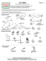
LAG
Shield
(x8)
HEX
Bolt
(x8)
Socket set
LAG Bolt
(x8)
Toggle
Anchor
(x8)
Stud Finder
If Drywall
Drill
Drill bit set
Assembly Instructions
www.video-furn.com 190 Don Hillock Drive|Aurora|Ontario|L4G 0G9
1.877.834.3876
TP4000 Wall stand
Thank you for purchasing Stand TP4000.
This Stand accommodates from single 40” up to dual 70” displays not exceeding 280lbs total.
If you cannot understand these instructions or are concerned about safety of the installation
Contact a qualified contractor or contact AVFI at 1-877-834-3876.
Read through entire instructions before beginning assembly.
This assembly will require a minimum of 2 people.
Main box- Supplied Parts
Supplied hardware bag ( in main box.)
Tools required
LFT-WM
Hardware bag
Mount Parts- Box 2 Parts and quantity
will vary depending on model.
Rectangular tube
(1)
TV hardware bag
Single (1)-Dual (2)
TV Brackets
Single (2) Dual(4)
TP4000
Body
Tube Bracket
(Inside TP4000 body)
Pencil
Tools required if Stud wall.

Unpack , Unlock
and Lift off front
panels.
Remove tube
bracket from
inside.
Find and mark studs if stud wall.
Preferably over outlet.
Position TP4000 Body with holes
Lined up over stud centers.
Mark hole locations.
Assembly Instructions
www.video-furn.com 190 Don Hillock Drive|Aurora|Ontario|L4G 0G9
1.877.834.3876
1
2
Stud Finder
If Drywall

Drill holes
Drywall w steel stud Drywall w wood stud Masonry
1 / 4 “Drill 1 / 2 “ Drill
Lag Shield
Assembly Instructions
www.video-furn.com 190 Don Hillock Drive|Aurora|Ontario|L4G 0G9
1.877.834.3876
3
Attach TP4000 body to wall
Using above bolts.
4
1 / 2 “ Drill

Install the tube Bracket.
Height will determine
approx. center of TV height.
Rack mount equipment.
Run wiring/cables.
Assembly Instructions
www.video-furn.com 190 Don Hillock Drive|Aurora|Ontario|L4G 0G9
1.877.834.3876
Bump faces up
Remove M8 bolts
5
6
Reinstall Panels.
7
X
Allen key is in
TV
HW Bag
M10 Nut x4
from back

Assembly Instructions
www.video-furn.com 190 Don Hillock Drive|Aurora|Ontario|L4G 0G9
1.877.834.3876
TV VESA patterns up to 1100mm x 650mm
Max TV Weight 200 lbs.
M8
SHCS Bolt
x4
TV 52-70
HW Bag
Attach TV brackets to TV using
provided hardware.
Do not overtighten.
8
9
Insert tube.
(may be longer than shown)
Attach bolts for leveling.
(removed in step5)
Level tube.

Assembly Instructions
www.video-furn.com 190 Don Hillock Drive|Aurora|Ontario|L4G 0G9
1.877.834.3876
10
11
Loosen lock by removing
bottom M8 bolt.
Lower to bottom.
A) Hang TV’s on tube.
B) Install cables/power.
C) Center and align TV’s.
D) Push up lock and tighten
from bottom with M8 bolt.
Front panel not shown
Finished
Thanks for Purchasing AVFI.
/


