MPS 112 and MPS 112CS
Media Presentation Switchers
68-706-01 Rev. H
01 07

This symbol is intended to alert the user of important operating and maintenance
(servicing) instructions in the literature provided with the equipment.
This symbol is intended to alert the user of the presence of uninsulated dangerous
voltage within the product’s enclosure that may present a risk of electric shock.
Caution
Read Instructions • Read and understand all safety and operating instructions before using the equipment.
Retain Instructions • The safety instructions should be kept for future reference.
Follow Warnings • Follow all warnings and instructions marked on the equipment or in the user
information.
Avoid Attachments • Do not use tools or attachments that are not recommended by the equipment
manufacturer because they may be hazardous.
Warning
Power sources • This equipment should be operated only from the power source indicated on the product. This
equipment is intended to be used with a main power system with a grounded (neutral) conductor. The
third (grounding) pin is a safety feature, do not attempt to bypass or disable it.
Power disconnection • To remove power from the equipment safely, remove all power cords from the rear of
the equipment, or the desktop power module (if detachable), or from the power source receptacle (wall
plug).
Power cord protection • Power cords should be routed so that they are not likely to be stepped on or pinched by
items placed upon or against them.
Servicing • Refer all servicing to qualifi ed service personnel. There are no user-serviceable parts inside. To
prevent the risk of shock, do not attempt to service this equipment yourself because opening or removing
covers may expose you to dangerous voltage or other hazards.
Slots and openings • If the equipment has slots or holes in the enclosure, these are provided to prevent
overheating of sensitive components inside. These openings must never be blocked by other objects.
Lithium battery • There is a danger of explosion if battery is incorrectly replaced. Replace it only with the
same or equivalent type recommended by the manufacturer. Dispose of used batteries according to the
manufacturer’s instructions.
Ce symbole sert à avertir l’utilisateur que la documentation fournie avec le matériel
contient des instructions importantes concernant l’exploitation et la maintenance
(réparation).
Ce symbole sert à avertir l’utilisateur de la présence dans le boîtier de l’appareil
de tensions dangereuses non isolées posant des risques d’électrocution.
Attention
Lire les instructions• Prendre connaissance de toutes les consignes de sécurité et d’exploitation avant
d’utiliser le matériel.
Conserver les instructions• Ranger les consignes de sécurité afi n de pouvoir les consulter à l’avenir.
Respecter les avertissements • Observer tous les avertissements et consignes marqués sur le matériel ou
présentés dans la documentation utilisateur.
Eviter les pièces de fi xation • Ne pas utiliser de pièces de fi xation ni d’outils non recommandés par le
fabricant du matériel car cela risquerait de poser certains dangers.
Avertissement
Alimentations• Ne faire fonctionner ce matériel qu’avec la source d’alimentation indiquée sur l’appareil. Ce
matériel doit être utilisé avec une alimentation principale comportant un fi l de terre (neutre). Le troisième
contact (de mise à la terre) constitue un dispositif de sécurité : n’essayez pas de la contourner ni de la
désactiver.
Déconnexion de l’alimentation• Pour mettre le matériel hors tension sans danger, déconnectez tous les cordons
d’alimentation de l’arrière de l’appareil ou du module d’alimentation de bureau (s’il est amovible) ou
encore de la prise secteur.
Protection du cordon d’alimentation • Acheminer les cordons d’alimentation de manière à ce que personne ne
risque de marcher dessus et à ce qu’ils ne soient pas écrasés ou pincés par des objets.
Réparation-maintenance • Faire exécuter toutes les interventions de réparation-maintenance par un technicien
qualifi é. Aucun des éléments internes ne peut être réparé par l’utilisateur. Afi n d’éviter tout danger
d’électrocution, l’utilisateur ne doit pas essayer de procéder lui-même à ces opérations car l’ouverture ou le
retrait des couvercles risquent de l’exposer à de hautes tensions et autres dangers.
Fentes et orifi ces • Si le boîtier de l’appareil comporte des fentes ou des orifi ces, ceux-ci servent à empêcher
les composants internes sensibles de surchauffer. Ces ouvertures ne doivent jamais être bloquées par des
objets.
Lithium Batterie • Il a danger d’explosion s’ll y a remplacment incorrect de la batterie. Remplacer uniquement
avec une batterie du meme type ou d’un ype equivalent recommande par le constructeur. Mettre au reut les
batteries usagees conformement aux instructions du fabricant.
Safety Instructions • English
Consignes de Sécurité • Français
Sicherheitsanleitungen • Deutsch
Dieses Symbol soll dem Benutzer in der im Lieferumfang enthaltenen
Dokumentation besonders wichtige Hinweise zur Bedienung und Wartung
(Instandhaltung) geben.
Dieses Symbol soll den Benutzer darauf aufmerksam machen, daß im Inneren des
Gehäuses dieses Produktes gefährliche Spannungen, die nicht isoliert sind und
die einen elektrischen Schock verursachen können, herrschen.
Achtung
Lesen der Anleitungen • Bevor Sie das Gerät zum ersten Mal verwenden, sollten Sie alle Sicherheits-und
Bedienungsanleitungen genau durchlesen und verstehen.
Aufbewahren der Anleitungen • Die Hinweise zur elektrischen Sicherheit des Produktes sollten Sie
aufbewahren, damit Sie im Bedarfsfall darauf zurückgreifen können.
Befolgen der Warnhinweise • Befolgen Sie alle Warnhinweise und Anleitungen auf dem Gerät oder in der
Benutzerdokumentation.
Keine Zusatzgeräte • Verwenden Sie keine Werkzeuge oder Zusatzgeräte, die nicht ausdrücklich vom
Hersteller empfohlen wurden, da diese eine Gefahrenquelle darstellen können.
Vorsicht
Stromquellen • Dieses Gerät sollte nur über die auf dem Produkt angegebene Stromquelle betrieben werden.
Dieses Gerät wurde für eine Verwendung mit einer Hauptstromleitung mit einem geerdeten (neutralen)
Leiter konzipiert. Der dritte Kontakt ist für einen Erdanschluß, und stellt eine Sicherheitsfunktion dar. Diese
sollte nicht umgangen oder außer Betrieb gesetzt werden.
Stromunterbrechung • Um das Gerät auf sichere Weise vom Netz zu trennen, sollten Sie alle Netzkabel
aus der Rückseite des Gerätes, aus der externen Stomversorgung (falls dies möglich ist) oder aus der
Wandsteckdose ziehen.
Schutz des Netzkabels • Netzkabel sollten stets so verlegt werden, daß sie nicht im Weg liegen und niemand
darauf treten kann oder Objekte darauf- oder unmittelbar dagegengestellt werden können.
Wartung • Alle Wartungsmaßnahmen sollten nur von qualifi ziertem Servicepersonal durchgeführt werden.
Die internen Komponenten des Gerätes sind wartungsfrei. Zur Vermeidung eines elektrischen Schocks
versuchen Sie in keinem Fall, dieses Gerät selbst öffnen, da beim Entfernen der Abdeckungen die Gefahr
eines elektrischen Schlags und/oder andere Gefahren bestehen.
Schlitze und Öffnungen • Wenn das Gerät Schlitze oder Löcher im Gehäuse aufweist, dienen diese zur
Vermeidung einer Überhitzung der empfi ndlichen Teile im Inneren. Diese Öffnungen dürfen niemals von
anderen Objekten blockiert werden.
Litium-Batterie • Explosionsgefahr, falls die Batterie nicht richtig ersetzt wird. Ersetzen Sie verbrauchte
Batterien nur durch den gleichen oder einen vergleichbaren Batterietyp, der auch vom Hersteller
empfohlen wird. Entsorgen Sie verbrauchte Batterien bitte gemäß den Herstelleranweisungen.
Este símbolo se utiliza para advertir al usuario sobre instrucciones importantes
de operación y mantenimiento (o cambio de partes) que se desean destacar en el
contenido de la documentación suministrada con los equipos.
Este símbolo se utiliza para advertir al usuario sobre la presencia de elementos con
voltaje peligroso sin protección aislante, que puedan encontrarse dentro de la caja
o alojamiento del producto, y que puedan representar riesgo de electrocución.
Precaucion
Leer las instrucciones • Leer y analizar todas las instrucciones de operación y seguridad, antes de usar el
equipo.
Conservar las instrucciones • Conservar las instrucciones de seguridad para futura consulta.
Obedecer las advertencias • Todas las advertencias e instrucciones marcadas en el equipo o en la
documentación del usuario, deben ser obedecidas.
Evitar el uso de accesorios • No usar herramientas o accesorios que no sean especifi camente recomendados
por el fabricante, ya que podrian implicar riesgos.
Advertencia
Alimentación eléctrica • Este equipo debe conectarse únicamente a la fuente/tipo de alimentación eléctrica
indicada en el mismo. La alimentación eléctrica de este equipo debe provenir de un sistema de distribución
general con conductor neutro a tierra. La tercera pata (puesta a tierra) es una medida de seguridad, no
puentearia ni eliminaria.
Desconexión de alimentación eléctrica • Para desconectar con seguridad la acometida de alimentación eléctrica
al equipo, desenchufar todos los cables de alimentación en el panel trasero del equipo, o desenchufar el
módulo de alimentación (si fuera independiente), o desenchufar el cable del receptáculo de la pared.
Protección del cables de alimentación • Los cables de alimentación eléctrica se deben instalar en lugares donde
no sean pisados ni apretados por objetos que se puedan apoyar sobre ellos.
Reparaciones/mantenimiento • Solicitar siempre los servicios técnicos de personal califi cado. En el interior no
hay partes a las que el usuario deba acceder. Para evitar riesgo de electrocución, no intentar personalmente
la reparación/mantenimiento de este equipo, ya que al abrir o extraer las tapas puede quedar expuesto a
voltajes peligrosos u otros riesgos.
Ranuras y aberturas • Si el equipo posee ranuras o orifi cios en su caja/alojamiento, es para evitar el
sobrecalientamiento de componentes internos sensibles. Estas aberturas nunca se deben obstruir con otros
objetos.
Batería de litio • Existe riesgo de explosión si esta batería se coloca en la posición incorrecta. Cambiar esta
batería únicamente con el mismo tipo (o su equivalente) recomendado por el fabricante. Desachar las
baterías usadas siguiendo las instrucciones del fabricante.
Instrucciones de seguridad • Español
Precautions
ᅝܼ乏ⶹ•Ё᭛
䖭Ͼヺোᦤ⼎⫼᠋䆹䆒⫼᠋ݠЁ᳝䞡㽕ⱘ᪡㓈ᡸ䇈ᯢDŽ
䖭Ͼヺো䄺ਞ⫼᠋䆹䆒ᴎݙ᳝ᲈ䴆ⱘॅ䰽⬉य़ˈ᳝㾺⬉ॅ䰽DŽ
⊼ᛣ
䯙䇏䇈ᯢк• 䑩ㅸỀ䑩嬦嫿⡈⼆枼敆嬼䍇夤ㆁ㙊⫊₩⏍Ề䑩嬵㕏ɿ
ֱᄬ䇈ᯢк• 䑩ㅸⷕ⪙⫊₩嬵㕏ᶧḦ⡈⭇㚦Ề䑩ɿ
䙉ᅜ䄺ਞ• 䑩ㅸⷕ徶⫉ᷨ␂⏍䑩ㅸ㉈⊘ᵋ䗅ㆁ㙊⫊₩⏍㐎ẝ嬵㕏ɿ
䙓ܡ䗑ࡴ• ᵎ壂Ề䑩嬦ᷨ␂⋃⒇㯢㙊㋩劑䗅₸ㅗ弾⇡嫿⡈澤Ḧ忀₎⊲斪ɿ
䄺ਞ
⬉⑤• 嬦嫿⡈⌫倾Ề䑩ᷨ␂ᵋ㝈㕏䗅䑶㷑ɿ嫿⡈⼆枼Ề䑩㙊♱一䗅Ờ䑶䰼丠Ờ䑶ɿ䩭ᵊ㚢一
澠♱ 一澡㕰⫊ ₩ 嫿 㓾澤ᵎ倾 ᵎ䑩 ㅗ 崴 弈ɿ
ᢨᥝ⬉⑤• ᵻ⫊₩♱ḏ嫿⡈㈕㋊䑶㷑澤嬸㈕㋊ㆁ㙊嫿⡈⍏ㅗ㞍暣䑶㷑䗅䑶㷑一澤ㅗḼẖ㋦ⅱⵃ
䑶䰼丠䗅䑶㷑一ɿ
⬉⑤㒓ֱᡸ• ⣦Ⓟⵄ一澤忀₎埬嵪嵐澤ㅗ愎䆪㉥⋌ɿ
㓈ᡸ•ㆁ㙊丵Ἧ⼆枼䑲嫥嬂䗅丵Ἧ᷻⎙弜垍ɿ嫿⡈怩㯢㙊䑩ㅸ⌰Ḧ㘵㊣䗅昷ḷɿᵻ忀₎℻
䋱大䑶⊲斪ᵎ壂儫ⴲ嬖☿㆔⹁嫿⡈䘗⪑丵Ἧ嬦嫿⡈ɿ
䗮亢ᄨ• 㙊ᷜ嫿⡈㙻⠴ᵋ㙊彛栏㤾ㅗ⪕澤⫄ḭ㕰䑩㚦敳㪣㙻㒐だ₄ḷ弈䀮ɿᵎ壂䑩Ḽẖᵝ
壀㉢Ẑ彛栏⪕ɿ
䫖⬉∴• ᵎ㪤䞯䗅㘵㊣䑶㮡ṛ㙊䅇㿹䗅⊲斪ɿ⼆枼Ề䑩ᵏ⋃⫷㋩劑䗅䘹⍍ㅗ䘹弒⛌⌸䗅䑶㮡ɿ
㉊䂨䑠ᷨ⋃䗅⸻嫯⡅䍇ⷠ⹄䑶㮡ɿ

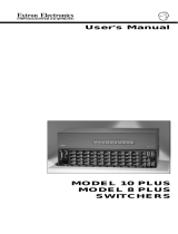
Quick Start — MPS Series
Installation
See chapter 2 for details.
Step 1
Turn off power to the MPS switcher and all other
devices that will be connected.
Step 2
Select your mounting option and install the
appropriate brackets. Mount the switcher.
Step 3
Attach up to four VGA, four S-video, and four
Video (composite) input devices (up to four of
each type) to the MPS switcher.
Step 4
Connect a VGA output, an S-video output, and a
Video (composite) output from the switcher to a
projector’s inputs.
Step 5
For stereo input, connect up to 12 audio sources
to the audio inputs of the VGA, S-video, or Video
(composite) groups (up to four audio sources for
each group). See chapter two, “Installation”, for
wiring diagrams.
Step 6
For stereo audio output, connect an audio output
device to each of the three output groups and one
audio amplifier to the Program Audio output
connectors. See chapter two, “Installation”, for
wiring diagrams.
Step 7
If the MPS switcher is to be connected to a
computer or host controller for remote control,
connect the host’s RS-232 cable to the 9-pin
female RS-232 remote connector of the switcher.
For more information, see the “Remote Control
Port (RS-232)” section in chapter five.
51
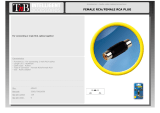
9
5
9
6
Female Male
1
6
RS-232 remote connector
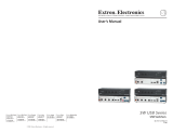
Step 8
Power up the input and output devices, then
connect power to the switcher’s rear AC
connector.
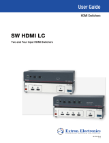
Connecting the MPS switcher
50
/60 H
z
1
0
0
-2
4
0
V
0.0
A
M
A
X
(VIDEO)
MPS 112
PROG OUT
O
UT
4
3
2
1
OUT
OUT
OUT
O
UT
RS-232
4
3
2
2
1
1
2
1
4
3
4
3
L
R
OUT
4
3
2
1
(S-VIDEO)
AUDIO
VIDEO
VGA(VGA)
PHANTOM
POWER
MIC IN
S-VIDEO
LRLR
Amplifier
Projector
VCR (4)DVD (4)
Microphone
Computer (2)
Laptop (2)
Speakers
Extron
MPS 112CS
Media Presentation
Switcher
#8 Screw (4 Plcs)
Each Side
Mounting Screws (2 Plcs)
Each Side
or
Supplied Rack Mounting Bracket
Optional Furniture Mounting Bracket
5
0
/6
0
H
z
1
0
0
-2
4
0
V
0
.5
A
M
AX
(V
ID
E
O
)
MPS 112
PROG OUT
OUT43
2
1
OUT
OUT
OUT
OUT
RS-232
43
2
2
1
1
2
1
4
3
4
3
L
R
OUT
4
3
21
(S
-V
ID
E
O
)
A
U
D
IO
V
ID
E
O
V
G
A
(V
G
A
)
M
IC
IN
S
-V
ID
E
O
Extron
MPS 112
Media Presentation
Switcher
Mounting options
Pin RS-232 function Description
1 – No connection
2 Tx Transmit data
3 Rx Receive data
4 – No connection
5 Gnd Signal ground
6, 7 – No connection
8, 9 – No connection
RS-232 remote connector pinout table

Quick Start — MPS Series, cont’d
Optimizing the audio
1. Finish installation and wiring as described on
the previous page, turn on all equipment, and
provide an input signal to the MPS switcher.
2. Reset program audio volume by pressing and
holding the Mode button, then pressing and
releasing the Prog Vol Reset button. Release
the Mode button to return to normal
operating mode.
3. Select an input with a signal present, and
adjust the volume of the audio amplifier
connected to the Prog Out audio connectors to
achieve the desired sound level.
4. Turn on or off the microphone power (15V for
MPS 112 and 48V phantom power for
MPS 112CS).
a. Press and hold the Mode button for more
than 2 seconds until the front panel LEDs
change to view mode
b. Press and release the Mic Power On/Off
button. On the MPS 112CS, the associated
LED lights.
5. Turn on the microphone by pressing the Mix
button (the associated LED lights).
6. Reset the microphone volume by pressing and
holding the Mode button, then pressing and
releasing the Mic Vol Reset button. Release
the Mode button to return to normal
operating mode.
7. Talk into the microphone in a normal voice
and adjust the Mic Volume knob to the
desired sound level.
8. Use the Program Volume and Mic Volume
knobs on the MPS switcher to adjust the
volume.
Setting the microphone
talk-over threshold
1. Finish installation wiring and setup as
described in the previous sections.
2. Turn on the microphone by pressing the Mix
button (the associated LED lights).
3. Speak into the microphone in a normal voice;
the main program audio level should drop
moderately. If it does not, lower the threshold
by pressing and holding the Mix button and
turning the Mic Volume knob counter-
clockwise. Release the Mix button to return to
normal operating mode.
4. Stop speaking into the microphone; the main
program audio should recover to the previous
level after approximately four seconds. If not,
increase the threshold by pressing and holding
the Mix button and turning the Mic Volume
knob clockwise. Release the Mix button to
return to normal operating mode.

i
MPS Series • Table of Contents
Table of Contents
Chapter 1 • Introduction ................................................................................. 1-1
About the MPS Series ......................................................................................... 1-2
MPS Series Features ............................................................................................ 1-2
Chapter 2 • Installation .......................................................................................................... 2-1
Mounting the Switcher .................................................................................................... 2-2
Rack mounting ................................................................................................................... 2-2
UL rack mounting requirements ....................................................................................... 2-2
Table or wall mounting ..................................................................................................... 2-3
Through-desk mounting .................................................................................................... 2-3
Rear Panel Connectors ..................................................................................................... 2-4
Connecting the MPS Switcher ...................................................................................... 2-5
Audio input and output .................................................................................................... 2-6
Connecting the RCA audio connectors ......................................................................... 2-6
Connecting the 3.5 mm mini-plugs ............................................................................... 2-7
Microphone input .............................................................................................................. 2-7
Connecting the 1/4" (6.3 mm) microphone connector (MPS 112) ................................. 2-7
Connecting the 3-pole captive screw microphone connector (MPS 112CS)................... 2-7
Program audio output (MPS 112CS) ................................................................................. 2-8
Remote connection ............................................................................................................ 2-8
Chapter 3 • Operation ............................................................................................................. 3-1
Front Panel Features ......................................................................................................... 3-2
Video/audio group buttons ............................................................................................... 3-2
Microphone and Program Audio controls ........................................................................ 3-2
Secondary button functions ............................................................................................... 3-2
Front Panel Operation ...................................................................................................... 3-3
Input selection in Single Switcher mode .......................................................................... 3-3
Input selection in Separate Switcher mode ...................................................................... 3-3
View Mode ......................................................................................................................... 3-4
Determining and selecting the switcher mode ................................................................ 3-4
Front panel security lockout (Executive mode) ................................................................ 3-5
Program audio ................................................................................................................... 3-5
Single Switcher mode ......................................................................................................... 3-5
Separate Switcher mode ............................................................................................... 3-5
Program audio volume ................................................................................................. 3-6
Reset program audio volume ....................................................................................... 3-6
Program audio mute .................................................................................................... 3-7
Talk-over (program ducking) ........................................................................................ 3-7
Microphone controls.......................................................................................................... 3-7
Turn mic or phantom power on/off .............................................................................. 3-7
Mic mix ......................................................................................................................... 3-7
Mic volume ................................................................................................................... 3-7
Reset mic volume .......................................................................................................... 3-7
Setting mic “talk-over” threshold ................................................................................ 3-7

MPS Series • Table of Contents
Table of Contents, cont’d
ii
68-706-01 Rev. H
01 07
Chapter 4 • Windows
®
-based Control Program ..................................................... 4-1
Installing the Windows-based Control Software ............................................... 4-2
Using the Software ............................................................................................................ 4-2
Uploading Firmware Updates ....................................................................................... 4-3
Chapter 5 • Programmer’s Guide ..................................................................................... 5-1
Remote Control Port (RS-232)....................................................................................... 5-2
Host-to-MPS Communications ...................................................................................... 5-2
MPS switcher-initiated messages ...................................................................................... 5-2
MPS switcher error responses ........................................................................................... 5-3
Command/Response Table .............................................................................................. 5-3
Using the command/response table ................................................................................. 5-3
Symbol definitions .............................................................................................................. 5-3
Command/Response Table for SIS Commands .................................................................. 5-4
Uploading firmware to the MPS via an SIS command ..................................................... 5-7
Appendix • Reference Information............................................................................... A-1
Specifications....................................................................................................................... A-2
Part Numbers ....................................................................................................................... A-6
Included parts ................................................................................................................... A-6
Optional accessories ......................................................................................................... A-6
Cables and connectors ...................................................................................................... A-7
Bulk cable ........................................................................................................................... A-7
Assorted connectors ........................................................................................................... A-7
Pre-cut cables ..................................................................................................................... A-8
All trademarks mentioned in this manual are the properties of their respective owners.

MPS Series
1
Chapter One
Introduction
About the MPS Series
MPS Series Features

MPS Series • Introduction
Introduction
1-2
About the MPS Series
The Extron MPS 112 and MPS 112CS are media presentation switchers featuring
three A/V switchers and a program audio switcher with microphone pre-amplifier
and mute controls in one product. The A/V switchers include a four input, one
output VGA/audio switcher; a four input, one output S-video/audio switcher; and
a four input, one output composite video/audio switcher. The MPS 112 and
MPS 112CS accept microphone input and mix the microphone signal with the main
audio in “talk-over” mode. Both models have an RS-232 control port. The MPS
112CS also features switchable 48 V phantom power for the microphone.
The MPS Series is a one box solution for small presentation systems.
Throughout this manual both models of this switcher are referred to as “MPS” or
“MPS 112” if the instructions are not model-specific.
MPS Series Features
Multiple video inputs — Twelve inputs can include four VGA (or SVGA, UXGA,
RGBHV, RGBS, RGsB, or RsGsBs) inputs on 15-pin HD female connectors,
four S-video (NTSC, PAL, or SECAM) inputs on 4-pin mini DIN female
connectors, and four composite video (NTSC, PAL, or SECAM) inputs on
BNC female connectors.
Multiple video outputs — Three outputs for simultaneous (in Separate mode), or
one at a time (in Single mode) display on VGA, S-video, or composite video
devices.
Multiple audio inputs — Twelve inputs can include four in the VGA group on
3.5 mm female stereo mini jacks, four in the S-video group on pairs of female
RCA connectors, and four in the Video group on pairs of female RCA
connectors.
Multiple audio outputs — One output for each group (VGA, S-video, and Video),
plus Program Out.
Program audio switcher — A three input, one output stereo audio switching
system allows the audio input of any video group to be selected for program
audio output, with volume and mute control. The MPS 112 features
unbalanced program audio output on RCA connectors, while the MPS 112CS
has balanced/unbalanced program audio output on a 5-pole captive screw
connector.
Bandwidth — Bandwidth is 350 MHz (-3 dB), typical for VGA video, allowing
this switcher to switch everything from NTSC video to high-resolution
computer displays.
Microphone input — The built-in microphone amplifier is switchable with
microphone power (MPS 112 – 15 V and MPS 112CS – 48 V phantom power).
The MPS 112 features unbalanced microphone input on one 1/4" (6.3 mm) jack,
while the MPS 112CS has balanced/unbalanced microphone input on a 3-pole
captive screw connector. The switcher includes a Mix button for “talk-over,”
with adjustable threshold control and mix volume control.
Front panel security lockout (Executive mode) — Locks out all front panel
functions except input selection and program volume control to prevent
unwanted setting changes.
RS-232 remote control — Allows remote control of the MPS switcher using
Extron’s Simple Instruction Set (SIS
™
), Extron’s control software for
Windows
®
, or a control system.
Rack-mountable — The 1U high, full rack width, metal enclosure is rack-
mountable, with supplied rack mounting brackets.

MPS 112 Series
2
Chapter Two
Installation
Mounting the Switcher
Rear Panel Connectors
Connecting the MPS Switcher

MPS Series • Installation
2-2
Installation
Mounting the Switcher
The MPS 112 and MPS 112CS are housed in 1U high, 17.4" wide metal enclosures
that are rack- or desk-mountable. The MBD 149 1U through-desk and rack
mounting kit (#70-077-03) is included with the switchers. The switchers may also be
surface-mounted under a table, desk, or podium, or on a wall, using the optional
Extron MBU 149 1U under-desk mounting kit (#70-222-01).
#8 Screw (4 Plcs)
Each Side
Mounting Screws (2 Plcs)
Each Side
or
Supplied Rack Mounting Bracket
Optional Furniture Mounting Bracket
50/60 H
z
100-240V
0.5A
M
A
X
(VIDEO)
MPS 112
PROG OUT
OUT
43
2
1
OUT
OUT
OUT
OUT
RS-232
43
2
2
1
1
2
1
4
3
4
3
L
R
OUT
4
3
21
(S-VIDEO)
AUDIO
VIDEO
VGA
(VGA)
MIC IN
S-VIDEO
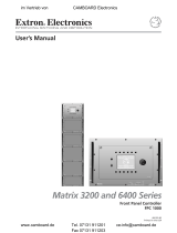
Figure 2-1 — Mounting the MPS switcher
Rack mounting
Rack mount the switcher as follows:
1. Attach the supplied rack mounting brackets to the switcher with the eight
provided #8 machine screws (figure 2-1).
2. Insert the switcher into the rack, aligning the holes in the mounting bracket
with those of the rack.
3. Secure the switcher to the rack using the supplied machine screws.
UL rack mounting requirements
The following Underwriters Laboratories (UL) requirements pertain to the safe
installation of the MPS in a rack.
1. Elevated operating ambient temperature — If installed in a closed or multi-
unit rack assembly, the operating ambient temperature of the rack
environment may be greater than room ambient temperature. Therefore,
install the device in an environment compatible with the maximum ambient
temperature (Tma = +122 °F, +50 °C) specified by Extron.
2. Reduced air flow — Install the equipment in a rack so that the amount of air
flow required for safe operation of the equipment is not compromised.
3. Mechanical loading — Mount the equipment in the rack so that a hazardous
condition is not achieved due to uneven mechanical loading.
4. Circuit overloading — Connect the equipment to the supply circuit and
consider the effect that circuit overloading might have on overcurrent
protection and supply wiring. Appropriate consideration of equipment
nameplate ratings should be used when addressing this concern.

MPS Series • Installation
2-3
5. Reliable earthing (grounding) — Maintain reliable grounding of rack-
mounted equipment. Pay particular attention to supply connections other
than direct connections to the branch circuit (e.g. use of power strips).
Table or wall mounting
The table/wall mounting brackets extend approximately 1/4" (6.4 mm) above the
top surface of the switcher enclosure. This design allows for an air space between
the enclosure and the surface to which it is mounted. Table or wall mount the
switcher as follows:
1. Attach the table/wall mounting brackets to the switcher with the eight
provided #8 machine screws (figure 2-1).
2. Hold the switcher with the attached brackets against the underside of the
table or other furniture, or against the wall. Mark the location of the screw
holes of the bracket on the mounting surface.
3. Drill 3/32" (2 mm) diameter pilot holes, 1/4" (6.4 mm) deep in the mounting
surface at the marked screw locations.
4. Insert #8 wood screws into the four pilot holes. Tighten each screw into the
mounting surface until just less than 1/4" of the screw’s head protrudes.
5. Align the mounting screws with the slots in the brackets and place the
switcher against the surface, with the screws through the bracket slots.
6. Slide the switcher slightly forward or back, then tighten all four screws to
secure the switcher in place.
Through-desk mounting
Mount the switcher through a desk or podium as follows:
1. Attach the supplied mounting brackets to the switcher with the machine
screws provided (figure 2-1).
2. Cut the proper sized hole in the mounting surface.
3. Hold the switcher with the attached brackets against the underside of the
table or other furniture. Mark the location of the screw holes of the bracket on
the mounting surface.
4. Drill 3/32" (2 mm) diameter pilot holes, 1/4" (6.3 mm) deep in the mounting
surface at the marked screw locations.
5. Insert four #8 wood screws through the bracket and into the four pilot holes.
Tighten all four screws to secure the switcher in place.

Installation, cont’d
MPS Series • Installation2-4
Rear Panel Connectors
50/60 Hz
100-240V 0.5A MAX
(VIDEO)
MPS 112
PROG OUT
OUT4321
OUT
OUT
OUT
RS-232
432
2
1
1
2
1
4
3
4
3
L
R
OUT4321
(S-VIDEO)
AUDIO
VIDEO VGA (VGA)
MIC IN
S-VIDEO
2 6 14 1693
5
7
8
11
10
4
1 15 17 18
Figure 2-2 — Rear panel of MPS 112
50/60 Hz
100-240V 0.5A MAX
(VIDEO)
MPS 112CS
PROG OUT
OUT4321
OUT
OUT
OUT
RS-232
432
2
1
1
2
1
4
3
4
3
L
R
OUT4321
(S-VIDEO)
AUDIO
VIDEO VGA (VGA)
(S-VIDEO)
LR
PHANTOM
POWER
MIC IN
2
6
14
16
9
8
10 191 15 17
5
7
12
4
13
3
Figure 2-3 — Rear panel of MPS 112CS
1
AC power — Standard AC power connector for a power source of
100 – 240 VAC, operating at 50/60 Hz
2
Video input group — Four female BNC connectors for composite video input
(numbered 1 through 4)
3
Video output — One female BNC connector for composite video output
4
S-video input group — Four female 4-pin mini DIN connectors for S-video
input (numbered 1 through 4)
5
S-video output — One female 4-pin mini DIN for S-video output
6
VGA input group — Four female 15-pin HD connectors for VGA input
(numbered 1 through 4)
7
VGA output — One female 15-pin HD connector for VGA output
8
RS-232 remote — One female 9-pin D connector for a host computer or a
controller using Extron’s Simple Instruction Set (SIS) or Windows-based
control software
9
(VGA) audio input group — Four 3.5 mm, female, stereo mini jacks for audio
input. See Audio input and output in this chapter.
To reduce crosstalk, it is recommended that you either terminate all the VGA
audio input jacks or avoid switching to a VGA audio input that has no device
connected to it.
10
(VGA) audio output — One 3.5 mm, female, stereo mini jack for audio output
from the VGA group input. See Audio input and output in this chapter.
11
Microphone input (MPS 112) — 6.3 mm mono microphone jack connection
for an external microphone

2-5MPS Series • Installation
12
Microphone input (MPS 112CS) — A 3-pole, 3.5 mm captive screw connector
socket for an external microphone
13
Phantom Power LED (MPS 112CS) — A green LED that indicates (when lit)
that phantom power is on
14
(S-video) audio input group — Eight female RCA connectors (four right and
four left) for audio input (numbered 1 through 4)
15
(S-video) audio output — Two female RCA connectors (one right and one left)
for audio output from the S-video group inputs. See Audio input and output in
this chapter.
16
(Composite Video) audio input group — Eight female RCA connectors (four
right and four left) for audio input (numbered 1 through 4)
17
(Composite Video) audio output — Two female RCA connectors (one right
and one left) for audio output from the Video group inputs. See Audio input
and output in this chapter.
18
Program Audio output (MPS 112) — Two female RCA (one right and one left)
for program audio output (unbalanced)
19
Program Audio output (MPS 112CS) — A 3.5 mm, 5-pole captive screw
connector socket for balanced or unbalanced program audio output
Connecting the MPS Switcher
The MPS switcher can be connected to as many as 12 input devices simultaneously
and can output to as many as three devices simultaneously, or one at a time. Follow
the steps below and see the installation example in figure 2-4.
1
Turn off power to the MPS switcher and all other devices that will be
connected.
2
If the MPS switcher is to be rack, table/wall, or through-desk mounted,
position the brackets and insert the mounting screws. See the Mounting the
Switcher, earlier in this chapter.
3
Attach up to four VGA, four S-video, and four video (composite) input
devices to the MPS switcher.
4
Connect the switcher’s VGA, S-video, and video (composite) outputs (up to
three, one of each video format) to a projector’s inputs.
5
For stereo audio input, connect up to 12 audio sources to the switcher’s audio
inputs of the VGA, S-video, or video (composite) groups (up to four for each
group). See the following Audio input and output section for connections.
6
For stereo output, connect an audio output device to each of the three groups
and one audio amplifier to the Program Audio connectors. Refer to Audio
input and output for wiring diagrams.
7
If the MPS switcher is to be connected to a computer or host controller for
remote control, connect the host’s RS-232 cable to the 9-pin female RS-232
connector of the MPS unit. For an RS-232 pinout table, see Remote connection
later in this chapter.

Installation, cont’d
MPS Series • Installation2-6
8
Power up the input and output devices, then connect power to the rear AC
connector of the MPS switcher.
50/60 H
z
100-240V
0.5A
M
A
X
(VIDEO)
MPS 112
PROG OUT
OUT
43
2
1
OUT
OUT
OUT
OUT
RS-232
43
2
2
1
1
2
1
4
3
4
3
L
R
OUT4
3
2
1
(S-VIDEO)
AUDIO
VIDEO
VGA
(VGA)
MIC IN
S-VIDEO
Amplifier
Projector
VCR (4)DVD (4)
Microphone
PC (2)
Laptop (2)
Speakers
Extron
MPS 112
Media Presentation
Switcher
Figure 2-4 — MPS 112 installation example
Audio input and output
Connecting the RCA audio connectors
1. Use pre-made RCA audio cables,
or
cut bulk audio cable, terminate the RCA plugs on the cable as shown in
figure 2-5.
Tip (+)
Sleeve ( )
Sleeve (Gnd )
Right Channel
(Red Jacket)
Left Channel
(White Jacket)
Tip (Signal)
Figure 2-5 — RCA audio connector
2. Plug RCA connectors into the MPS switcher.

2-7MPS Series • Installation
Connecting the 3.5 mm mini-plugs
1. Use pre-made Extron 3.5 mm audio cables,
or
cut bulk audio cable and solder the 3.5 mm mini-plug to the cable.
Sleeve ( )
Ring (R)
Tip (L)
3.5 mm Stereo Plug Connector
(unbalanced)
Figure 2-6 — 3.5 mm, mini-plug audio connector
2. Plug the 3.5 mm mini-plug connectors into the MPS 112.
Microphone input
Connecting the 1/4" (6.3 mm) microphone connector (MPS 112)
1. Use a pre-made 1/4" microphone cable,
or
cut bulk microphone cable and solder the 1/4" microphone connector to
the cable.
Tip (+)
Sleeve ( )
Figure 2-7 — 1/4" microphone connector
2. Plug the 1/4" microphone connector into the MPS 112.
Connecting the 3-pole captive screw microphone connector (MPS 112CS)
1. Use a pre-made 3-pole captive screw microphone cable,
or
cut bulk microphone cable, and attach the 3-pole captive screw connector
to the cable.
Balanced Mic InputUnbalanced Mic Input
Tip
Ring
Sleeve
Tip
Sleeve
Figure 2-8— 3.5 mm, 3-pole captive screw microphone connector
Do not tin the mic leads before installing into the connector. Tinned wires are
not as secure in the connector and could be pulled out.
2. Plug the 3-pole captive screw connector into the MPS 112CS.

Installation, cont’d
MPS Series • Installation2-8
DB9 Pin Locations
Female
51
96
Program audio output (MPS 112CS)
Balanced or unbalanced program audio output is available on the MPS 112CS using
a 3.5 mm, 5-pole captive screw connector. Refer to the following illustration for
proper wiring.
CAUTION
For unbalanced audio output, connect the sleeve(s) to the center ground
pin. DO NOT connect the sleeve(s) to the negative (-) contacts.
Tip
NO Ground Here
Sleeve(s)
Tip
NO Ground Here
Tip
Ring
Sleeve(s)
Tip
Ring
p p
LR
AUDIO
LR
AUDIO
Figure 2-9 — 3.5 mm, 5-pole captive screw audio connectors
Do not tin the audio leads before installing into the connector. Tinned wires
are not as secure in the connector and could be pulled out.
Remote connection
The cable used to connect the RS-232/Remote port to a computer or control
system may need to be modified by removing pins or cutting wires. If
unneeded pins are connected, the switcher may hang up.
For RS-232 control, use a control cable with only pins 2, 3, and 5 connected.
Otherwise, either cut the wires to the other pins in hard-shelled connectors or
remove the unneeded pins from molded plugs. See chapter 5, Programmer’s Guide,
for definitions of the SIS commands and details on how
to install and use the control software.
The RS-232 connector is a 9-pin D female with the
following pin designations:
Pin RS-232 function Description
1 – No connection
2 Tx Transmit data
3 Rx Receive data
4 – No connection
5 Gnd Signal ground
6, 7 – No connection
8, 9 – No connection
The RS-232 protocol is as follows:
• 9600 baud
• 8 data bits
• 1 stop bit
• no parity
• no flow control

MPS 112 Series
3
Chapter Three
Operation
Front Panel Features
Front Panel Operation

MPS 112 Series • Operation3-2
Operation
PRELIMINARY
Front Panel Features
Figure 3-1 — Front panel details of the MPS switcher (MPS 112 shown)
1
Executive Mode indicator LED — This red LED lights when Executive mode
(front panel lockout) is turned on.
Video/audio group buttons
The controls for the three independent switchers are grouped by input type.
2
VGA/Audio group — Buttons 1 through 4 select the input for the VGA/audio
switcher sections of the MPS unit. The LEDs to the right of each button (when
lit) indicate which input has been selected for output.
3
S-video/Audio group — Buttons 1 through 4 select the input for the S-video/
audio switcher sections of the MPS unit. The LEDs to the right of each button
(when lit) indicate which input has been selected for output.
4
Video/Audio group — Buttons 1 through 4 select the input for the composite
video/audio switcher sections of the MPS unit. The LEDs to the right of each
button (when lit) indicate which input has been selected for output.
Microphone and Program Audio controls
5
Mic Mix button — This button turns on the microphone mixer to provide
microphone talk-over for the program audio. The LED (when lit) indicates
that the microphone mixer is turned on.
6
Mic Volume — This adjustment knob controls the volume of the microphone.
7
Program Audio Volume — This adjustment knob controls the volume of the
program audio output.
8
Program Audio Mute — This button mutes the program audio output. The
LED (when lit) indicates that the program audio output is muted.
Secondary button functions
9
Mic Power On/Off — This is the secondary function of this button. Press and
release this button while pressing and holding the Mode button (
14
) for more
than 2 seconds to toggle the microphone power (MPS 112 – 15 V,
MPS 112CS – 48 V) on or off. The associated LED indicates if the mic power is
on (when lit) or off. When the Mode button is released, the LED resumes
input indication.
10
Mic Volume Reset — This is the secondary function of this button. Press and
release this button while pressing and holding the Mode button (
14
) to reset
the mic volume to a preset level. See Front Panel Operation in this chapter for
details. When the Mode button is released, the LED resumes input indication.
11
Program Volume Reset — This is the secondary function of this button. Press
and release this button while pressing and holding the Mode button (
14
) to
reset the Program Audio volume to a preset level. See Front Panel Operation in
this chapter for details. When the Mode button is released, the LED resumes
input indication.
MPS SERIES
MICPROGRAM AUDIOVIDEO / AUDIOS-VIDEO / AUDIOVGA / AUDIO
VOLUME
VOLUME
MUTE
432143214321
MIC POWER ON/OFFMIC VOL RESET PROG VOL RESET SEPARATESINGLEMODE
EXEC.MODE
MIX
MEDIA PRESENTATION SWITCHER
21 3 4
6
8
5
7
9
10
11
12
13
14

3-3MPS 112 Series • Operation
PRELIMINARY
Switcher Mode controls
12
Separate Switcher mode — This is the secondary function of this button.
Press and release this button while pressing and holding the Mode button (
14
)
to select the Separate Switcher mode. The associated LED indicates if the
Separate Switcher mode is on (when lit) or off. When the Mode button is
released, the LED resumes input indication.
13
Single Switcher mode — This is the secondary function of this button. Press
and release this button while pressing and holding the Mode button (
14
) to
select the Single Switcher mode. The associated LED indicates if the Single
Switcher mode is on (when lit) or off. When the Mode button is released, the
LED resumes input indication.
14
Mode — Press and hold this button for more than 2 seconds to view the
switcher status. It also allows mode and setting changes when used in
combination with other buttons, as previously indicated.
Front Panel Operation
Figure 3-2 — MPS switcher front panel
The functions of the front panel controls are described in the following sections.
Input selection in Single Switcher mode
In Single Switcher mode the switcher emulates one switcher with 12 inputs. In this
mode, when one of the inputs is selected, the input is routed to the outputs (video
and audio) for that group, and the audio is sent to the program audio output as
well. All of the other outputs are muted.
When you select and press an input button in Single Switcher mode, the green LED
indicator to the right of the button lights steadily. All of the other LEDs turn off. To
select a different input, press a different input button.
The Extron IR 102 Universal Handheld Remote Control can be used with an
MPS 112 switcher only when the switcher is in Single Switcher mode.
The MPS 112 must be in Single Switcher mode if it is to be slaved to an
Extron MLC (Medialink
™
Controller).
Input selection in Separate Switcher mode
There are three input selection groups on the front panel: VGA/Audio,
S-video/Audio, and Video/Audio. These groups correspond to the three
independent A/V switchers (in Separate Switcher mode) available in the MPS 112.
Each of the input selection groups has four numbered input selection buttons
(1 through 4), which allow you to choose from among the four separate input
sources in that group that the switcher can output.
All outputs of the three groups are active, but the audio from only one group is
routed to the program audio output. That group (input) is indicated by a flashing
LED, while the other two groups are indicated by solid LEDs. See the Program
Audio section in this chapter for more details.
MPS SERIES
MICPROGRAM AUDIOVIDEO / AUDIOS-VIDEO / AUDIOVGA / AUDIO
VOLUME
VOLUME
MUTE
432143214321
MIC POWER ON/OFFMIC VOL RESET PROG VOL RESET SEPARATESINGLEMODE
EXEC.MODE
MIX
MEDIA PRESENTATION SWITCHER

Operation, cont’d
MPS 112 Series • Operation3-4
PRELIMINARY
View mode
To view the switcher’s current mode and microphone power settings, press and
hold the Mode button for more than 2 seconds. The LEDs on the front panel change
from input indication to setting indication.
To change a setting, continue to hold the Mode button, and press the button that
corresponds to the setting you want to change. Figure 3-3 shows the front panel
buttons and LEDs that are active during View mode. Release the Mode button and
the front panel LEDs resume input indication.
Changes to the Single Switcher mode and Separate Switcher mode do not take
effect until the Mode button is released.
Figure 3-3 — Front panel button/LED functions during View mode
Determining and selecting the switcher mode
The current switcher mode is indicated by the input LEDs. If the unit is in Separate
Switcher mode, up to four LEDs can be lit. In Single Switcher mode, only 1 LED is
lit and the other 11 input LEDs are off.
To change modes, press and hold the Mode button for more than 2 seconds, then
press either the Single (to enter the Single Switcher mode) or Separate (to enter the
Separate Switcher mode) button. Release the Mode button when your selection has
been made.
VGA / AUDIO
14321
SEPARATESINGLEMODE
EXEC.MODE
Press and hold the Mode button and press the VGA/Audio
input 4 button to toggle Executive mode (front panel
lockout) on and off. The LED lights when the mode is on.
1
MODE
EXEC.MODE
PROGRAM AUDIOVIDEO / AUDIO
VOLUME
MUTE
432
MIC POWER ON/OFFMIC VOL RESET PROG VOL RESET
Press and hold the Mode button and press the Mic Power On/Off
button to toggle the microphone power on and off.
The LED lights when microphone power is on.
VGA / AUDIO
14321
SEPARATESINGLEMODE
EXEC.MODE
Press and hold the Mode button and press the
Separate button to select Separate Switcher mode.
NOTE The mode does not change until the Mode
button is released.
VGA / AUDIO
14321
SEPARATESINGLEMODE
EXEC.MODE
Press and hold the Mode button and press the
Single button to select Single Switcher mode.
NOTE The mode does not change until the
Mode button is released.
VGA / AUDIO
14321
SEPARATESINGLEMODE
EXEC.MODE
Press and hold the
Mode button for more
than 2 seconds to
enter View mode.
S-VIDEO
2
VGA / AUDIO
14321
SEPARATESINGLEMODE
EXEC.MODE
Press and hold the Mode button and press the S-video/Audio
input 1 button to toggle Follow sub-mode on and off.
The LED lights when the mode is on. See pg. 3-6.
Page is loading ...
Page is loading ...
Page is loading ...
Page is loading ...
Page is loading ...
Page is loading ...
Page is loading ...
Page is loading ...
Page is loading ...
Page is loading ...
Page is loading ...
Page is loading ...
Page is loading ...
Page is loading ...
Page is loading ...
Page is loading ...
Page is loading ...
Page is loading ...
Page is loading ...
Page is loading ...
Page is loading ...
Page is loading ...
Page is loading ...
Page is loading ...
Page is loading ...
Page is loading ...
/