Page is loading ...

Setup Guide — MPS 112 Series
Installation
Step 1 — Disconnect power
Turn off or disconnect all equipment power sources.
Step 2 — Mount the unit
Select a mounting option and install the appropriate brackets. Mount the switcher.
Step 3 — Connect video inputs
Attach up to four VGA, four S-video, and four Video (composite) input devices to the MPS switcher.
Step 4 — Connect video outputs
Connect a VGA output, an S-video output, and a Video (composite) output from the switcher to the appropriate projector inputs.
Step 5 — Connect audio inputs
For stereo input, connect up to 12 audio sources to the audio inputs of the VGA, S-video, or Video (composite) groups (up to
four audio sources for each group). Stereo audio in the VGA group is input via standard 3.5mm stereo mini connectors. Stereo
or mono audio in the Video and S-Video groups are input on standard female RCA connector pairs.
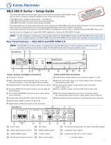
Step 6 — Connect Mic input
If a microphone is required, connect it to the 1/4" connector on the
MPS 112 or the 3-pole, 3.5mm captive screw connector on the MPS 112CS,
as shown.
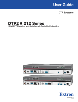
Step 7 — Connect audio outputs
For stereo audio output, connect an audio output device to each of the three output groups. Connect an audio amplifier to the
Program Audio output connectors (female RCA connectors on the MPS 112, 3.5mm captive screw connectors on the MPS 112CS).
This guide provides basic instructions for an experienced installer to set up
and operate the Extron MPS 112/112CS media switcher.
(Continued on reverse side)
MPS SERIES
MICPROGRAM AUDIOVIDEO / AUDIOS-VIDEO / AUDIOVGA / AUDIO
VOLUME
VOLUME
MUTE
432143214321
MIC POWER ON/OFFMIC VOL RESET PROG VOL RESET SEPARATESINGLEMODE
EXEC.MODE
MIX
MEDIA PRESENTATION SWITCHER
Balanced Mic InputUnbalanced Mic Input
Tip
Ring
Sleeve
Tip
Sleeve
CAUTION
For unbalanced audio, connect the
sleeve(s) to the ground contact.
DO NOT connect the sleeve(s) to the
negative (-) contacts.
Tip
Ring
Tip
Ring
L R
Sleeve(s)
Do not tin the wires!
Tip
NO Ground Here
Sleeve(s)
NO Ground Here
Tip
L R
Balanced Audio Output Unbalanced Audio Output
RS-232 Pin
Configuration
Pin Signal
2 Tx
3 Rx
5 Ground
DB9 Pin Locations
Female
51
96
RS-232 remote connector
Step 8 — Connect RS-232 port
If the MPS switcher is to be connected to a computer or host controller for remote
control, connect the host RS-232 cable to the switcher 9-pin female RS-232 remote
connector. For additonal information, see the "Remote Control Port (RS-232)" section
in chapter 5 of the MPS 112 User’s Manual.
RS-232 protocol:
• 9600 baud • no parity
• 8 data bits • no ow control
• 1 stop bit

Setup Guide — MPS 112 Series, cont’d
© 2009 Extron Electronics. All rights reserved.
Extron USA - West
Headquarters
+800.633.9876
Inside USA / Canada Only
+1.714.491.1500
+1.714.491.1517 FAX
Extron USA - East
+800.633.9876
Inside USA / Canada Only
+1.919.863.1794
+1.919.863.1797 FAX
Extron Europe
+800.3987.6673
Inside Europe Only
+31.33.453.4040
+31.33.453.4050 FAX
Extron Asia
+800.7339.8766
Inside Asia Only
+65.6383.4400
+65.6383.4664 FAX
Extron Japan
+81.3.3511.7655
+81.3.3511.7656 FAX
Extron China
+400.883.1568
Inside China Only
+86.21.3760.1568
+86.21.3760.1566 FAX
Extron Middle East
+971.4.2991800
+971.4.2991880 FAX
68-706-50
Rev. A
04 09
Step 9 — Connect Power
Power up the input and output devices, then connect power to the rear AC connector of the MPS 112.
Optimizing the audio
1. Finish the installation and wiring as described, turn on all equipment, and provide an input signal to the switcher.
2. Reset the program audio volume by pressing and holding the Mode button, then pressing and releasing the
Prog Vol Reset button. Release the Mode button to return to normal operating mode.
3. Select an input with a signal present, and adjust the volume of the audio amplifier connected to the Prog Out audio con-
nectors to achieve the desired sound level.
4. Toggle microphone power (15V for MPS 112 or 48V phantom power for MPS 112CS) on or off as required:
a. Press and hold the Mode button for more than 2 seconds.
b. Press and release the Mic Power On/Off button. The associated LED lights when mic power is on.
5. Turn on the microphone by pressing the Mix button (the associated LED lights).
6. Reset the microphone volume by pressing and holding the Mode button, then pressing and releasing the Mic Vol Reset
button. Release the Mode button to return to normal operating mode.
7. Talk into the microphone in a normal voice and adjust the Mic Volume knob to the desired sound level.
8. Use the Program Volume and Mic Volume knobs on the MPS switcher to adjust the volume.
Setting the microphone talk-over threshold
1. Set the program audio and microphone levels as described in "Optimizing the audio".
2. Turn on the microphone by pressing the Mix button (the associated LED lights).
3. Speak into the microphone in a normal voice. The main program audio level should drop moderately. If not, lower the
threshold by pressing and holding the Mix button and turning the Mic Volume knob counter‑clockwise. Release the Mix
button to return to normal operating mode.
4. Stop speaking into the microphone; the main program audio should recover to the previous level after approximately 4
seconds. If not, increase the threshold by pressing and holding the Mix button and turning the Mic Volume knob clock-
wise. Release the Mix button to return to normal operating mode.
Single/Separate Switcher Operation
The MPS 112 can be configured for operation in two modes: Single or Separate. Single mode emulates one switcher with 12
inputs. Separate mode emulates three separate switchers. Single or Separate mode is selected by pressing and holding the
Mode button for more than 2 seconds, then pressing and releasing the Single or Separate button depending upon the desired
operating mode.
Single Switcher Operation
In Single switcher mode, when an input is selected the input audio and video is routed to the output for that group, and the
audio is also sent to the program audio output. All other outputs are muted. When selected, the green LED indicator to the
right of the input button lights steadily. All other input LEDs are off. To select another input, press a different input button.
Separate Switcher Operation
In Separate switcher mode, the switcher acts as three independent switchers within the three input groups: VGA/Audio,
S‑video/Audio, and Video/Audio. Each group has a video and audio output for its group that are always active. Program
audio comes from the last input selected and is indicated by a ashing input LED. For additonal information, see the
"Program Audio" section in chapter 3 of the MPS 112 User’s Manual.
/