Page is loading ...

ISM RGB Output Board • Setup Guide
The Extron
®
ISM RGB is a
universal video and RGB
scaler, analog output board
for the ISM 824. It has five BNC
connectors and a local audio
output. The board mounts in one of the four vertical expansion slots (numbered 1 to 4)
at the rear of the ISM 824. Refer to the ISM 824 User Guide, online at www.extron.com
for operating details.
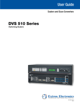
To install an ISM RGB output board in the ISM 824 base unit,
1. Turn off the ISM 824. Remove the power cord. Repeat for all connected devices.
2. Select an open slot at the rear, or take out a blank plate by removing the two
retaining screws (top and bottom), and lifting the plate away.
NOTE: Retain and re-use the screws to secure the new output board in place. Retain
the blank plates. If a board is installed in the desired slot, remove the screws
and carefully pull out the board.
3. Holding the new board by the frame, align
the front (non-connector end) of the board
with the top and bottom plastic guides in the
ISM 824. Slide the board in carefully, keeping
within the guides. Push it into place firmly,
and secure it with the retained screws.
4. If required, repeat steps 2 through 4
for any other output boards.
5. Power on the ISM 824. Any new output
boards are auto-detected, and take
approximately 30 seconds to initialize. The
16 character LCD display indicates the new
board type, slot used, and counts down the
initialization time. See inset for example display for a new
ISM RGB board installed in slot #2, with 23 seconds left.
6. Following the image at right, connect output device
cables to the BNC connectors to output RGBHV, RGBS
video, RGsB, or HD component video signals. The output can
be configured from the front panel (see page 2) or by SIS
™
commands (see page 3).
7. Insert a 5-pole captive screw connector into the local audio
output connector for balanced or unbalanced stereo audio
output. Wire the connector as shown below.
1
100
-
240
50/60 Hz
1.2A MAX.
1
2 3 4 5 6 7
8
2
1 2
3 4 5 6 7 8
1
2
1
INPUTS
OUTPUTS
R/R-Y
G/Y
VID
B/C
B-Y
H/HV
V
R/R-Y
G/Y
VID
B/C
B-Y
H/HV
V
PASS THRU
INPUTS
RESET
LAN
REMOTE
RS232/RS422
ACT
LINK
OUTPUT
VIDEO
SCALER
70-545-01
3
R/
R-Y
G/Y
B/
B-Y
H/
HV
V
OUTPUT
UNIV.
SCALER
70-544-01
5
R/
R-Y
G/Y
B/
B-Y
H/
HV
V
OUTPUT
PASS
THRU
70-547-01
8
R/
R-Y
G/Y
B/
B-Y
H/
HV
V
Extron
ISM 824
Integration Scaling
Matrix Switcher
Align output board
with top and bottom
plastic guides.
R/
R-Y
G/Y
B/
B-Y
H/
HV
V
OUTPUT
7
SCAN
CONV.
70-546-01
Example Output Board Installation
New UnivScaler
Slot #2 23
ISM RGB
R/
R-Y
G/Y
B/
B-Y
H/
HV
V
L
R
UNIV.
SCALER
H/
HV
RGBHV
Video
RGsB or
Component
Video
RGBS
Video
V
H/
HV
V
H/
HV
V
R/
R-Y
G/Y
B/
B-Y
R/
R-Y
G/Y
B/
B-Y
R/
R-Y
G/Y
B/
B-Y
Unbalanced Stereo Output
Balanced Stereo Output
Tip
Ring
Sleeve(s)
Tip
Ring
L R
Left
Right
Tip
Sleeve(s)
Tip
L R
Left
Right
NO GROUND HERE.
NO GROUND HERE.
CAUTION: For unbalanced audio, DO NOT not connect the sleeves to the
negative contacts. Connect to center ground contact.

Selec t O utp ut
#5 U niv Sca ler
Next
Input Se tup
#5 U niv Sca ler
Aspec t R ati o
4:3
Next
Rotate either encoder
to select Aspect Ratio
(4:3 or 16:9)
Next
H Start V
128 1 28
Rotate encoder to
adjust H(orizontal) start
Rotate encoder to
adjust V(ertical) start
Next
Tota l Pix Phase
1728 0 0
Rotate encoder to
adjust Total Pix value
Rotate encoder to
adjust Phase value
Next
H Activ e V
1283 10 28
Rotate encoder to
adjust H active value
Rotate encoder to
adjust V active value
Menu
Next
Outpu t C onf ig
#5 U niv Sca ler
30 sec.
RGBHV
Outpu t Type
Rotate encoder to
adjust resolution
Rotate encoder to
adjust refresh rate
Next
H - V -
Sync Pola rit y
Next
Rotate either encoder
to change sync polarity
(H- V-, H- V+, H+ V-, H+ V+)
1024x 768 6 0
Resol uti on
Next
Rotate either encoder
to select output type
(RGBHV, RGBS,
RGsB, YUV Bi-Level,
YUV Tri-Level)
NextNext
Menu
User Pre set s
#5 U niv Sca ler
30 sec.
<NA> 1 2 3
Save Preset
Next
Rotate either encoder
to select a preset to
save current settings
<NA> 1 2 3
Erase Pr ese t
Next
Rotate either encoder
to select a preset
to erase
Adva nced Config
#5 U niv Sca ler
Next
None
Te st Patt ern
Rotate either encoder
to select a test pattern
<Off> On
Blue Mod e
Next
Rotate either encoder
to turn blue mode On
or Off
Off <O n>
Film Mod e
Next
Rotate either encoder
to turn film mode On
or Off
<Off> On
RGB Pas sthrough
Next
Rotate either encoder
to turn RGB
passthrough On or Off
Next
Menu
Next
Next
Rotate encoder to
select input
Rotate encoder to
turn On or Off
Input # 2 O n
Auto Imag e
Auto Me mories
Next
Rotate either encoder
to turn auto memories
On or Off
Off <O n>
Next
Input #2 Of f
Full Scr een
Rotate encoder to
select input
Rotate encoder to
turn On or Off
NOTE: Within any submenu, press the Menu button
to go directly to the top level (Output Card
Configuration) menu. If, for 30 seconds, no
button is pressed or adjust knob is rotated,
the menu times out and reverts to the default
display cycle.
ISM RGB Output Board • Setup Guide, cont’d
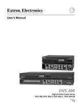
ISM RGB configuration menu
Using the front panel menu buttons (Menu and Next), the ISM RGB board
configuration menu can be accessed. From the Output Configuration screen, press
Next until reaching the #x UnivScaler menu (see the image below). Press Menu and
Next to navigate through the menus and use the front panel adjustment knobs
({ [), to change the settings as desired. For full menu details see the ISM 824 User
Guide, online at www.extron.com.
From the default cycle press Menu repeatedly to reach the Output
Configuration menu. Press Next (enters Select Output menu) and rotate
either adjust knob to select the Universal Scaler menu. Follow the figure
below and use the Adjust knobs to change value as desired.
MENU NEXT
ADJUST
2
Input Setup
The Input Setup submenu allows configuration of aspect ratios,
horizontal and vertical start points, total pixels, phase value,
and the horizontal and vertical areas. Rotate one or both Adjust
knobs as required to change values.
Output Config
The Output Config submenu displays and allows changing the
format of the scaler output. Use the adjust knobs to select a
resolution and refresh rate, to select signal type (RGBHV, RGBS,
RGsB, HD or component video YUV), and to change the sync
polarity. For the resolution and rates see the table on page 3.
User Presets
The User Presets submenu displays and allows the current settings
to be saved as a preset, or to erase an existing saved preset.
Use the Adjust knobs to select between the presets.

3
SIS command definitions and table continues on page 4.
Resolution 50 Hz 60 Hz 72 Hz 75 Hz 96 Hz 100 Hz 120 Hz 59.94 Hz
640x480 X X X X X X
800x600 X X X X X X
852x480 X X X X X
1024x768 X X X X
1024x852 X X X X
1024x1024 X X X
1280x768 X X X X
1280x800 X X
1280x1024 X X X
1360x765 X X X
1365x768 X X X
1366x768 X X X
1365x1024 X X
1400x1050 X X
1440x900 X X
1600x1200 X X
1680x1050 X
1920x1200 X
480p X X
576p X X
720p X X X
1080i X X X
1080p X X X
1080p Sharp X
Advanced Config
Within this submenu the following settings can be adjusted: auto Image (on or off),
test pattern (selection), blue mode (on or off), auto memories (on or off), film mode
(on or off), and RGB pass-through (on or off), and full screen (on or off).
Test pattern
The test pattern submenu offers the following test patterns: split color bars, two
crosshatch patterns, grayscale, ramp, alternating pixels, crop, and four aspect ratios.
Board-specific SIS
™
commands
Alternatively, the ISM RGB board can be configured with specific Special Instruction
Set
™
(SIS) commands. The table on page 4 list some of the ISM RGB board-specific
commands. Command definitions begin below and continue on page 4. For a full list
of SIS commands refer to the ISM 824 User Guide, online at www.extron.com.
NOTE: X! = Input number, 0-8
X@ = Output number, 1-8
X1) = Mode status, 1 = on, 0 = off
X2!
= Output resolution, 01 = 640x480, 02 = 800x600, 03 = 852x480, 04 = 1024x768,
05 = 1024x852, 06 = 1024x1024, 07 = 1280x768, 08 = 1280x1024, 09 = 1360x765,
10 = 1365x768, 11 = 1366x768, 12 = 1365x1024, 13 = 1400x1050, 14 = 1600x1200,
15 = 480p, 16 = 576p, 17 = 720p, 18 = 1080i, 19 = 1080p, 20 = 1280x800,
21 = 1440x900, 22 = 1680x1050, 23 = 1920x1200, 24 = 1080p Sharp

Extron USA - West
Headquarters
+800.633.9876
Inside USA / Canada Only
+1.714.491.1500
+1.714.491.1517 FAX
Extron USA - East
+800.633.9876
Inside USA / Canada Only
+1.919.863.1794
+1.919.863.1797 FAX
Extron Europe
+800.3987.6673
Inside Europe Only
+31.33.453.40 40
+31.33.453.40 50 FAX
Extron Asia
+800.7339.8766
Inside Asia Only
+65.6383.440 0
+65.6383.466 4 FA X
Extron Japan
+81.3.3511.7655
+81.3.3511.7656 FAX
Extron China
+400.883.1568
Inside China Only
+86.21.3760.1568
+86.21.3760.1566 FAX
Extron Middle East
+971.4.29 91800
+971.4.29 91880 FAX
68-1123-62
Rev A
08 10
© 2010 Extron Electronics. All rights reserved. www.extron.com
ISM RGB Output Board • Setup Guide, cont’d
4
Command ASCII
command
(host to ISM)
Response
(ISM to host)
Additional description
Input selection
Video and
audio
X!*X@! OutX@•InX!•All
]
Tie video and audio input X! to
output X@.
Video
X!*X@& OutX@•InX!•RGB
]
Tie video input X! to output X@.
Audio
X!*X@$ OutX@•InX!•Aud
]
Tie audio input X! to output X@.
Output scaler rate
Set output
rate
X@
*
X2!
*
X2@
= RteX@ *X2!*X2@
]
Set the resolution and refresh rate
View
X@
= X2!*X2@
]
View selected output rate
Start auto image
Start auto
image
14*X@# ImgX@
]
Auto image input tied to output X@.
Auto memory
On
X@*1M X@
Aut1
]
Set auto memory to on.
Off
X@*0M X@
Aut0
]
Set auto memory to off.
View setting
X@M
X1)]
View current auto memory.
Auto image
Enable
55*X@* X!*1# X@ImgX!*1
]
Activates auto image for all inputs.
Disable
55*X@* X!*0# X@ImgX!*0
]
Turns auto image off.
View
55*X@* X!#
X1)
]
View auto image on/off setting.
Input aspect ratio
16:9
9*X@*1# X@AspX!*1
]
Set input aspect ratio 16:9
.
4:3
9*X@*0# X@AspX!*0
]
Set input aspect ratio 4:3
.
View
9*X@#
X5%
]
View current aspect ratio.
Full screen
Enable
99*X@*X!*1# X@FulX!*1
]
Output on full screen.
Disable
99*X@*X!*0# X@FulX!*0
]
Turn full screen off.
View
99*X@*X!#
X1)
]
View the full screen status.
SIS definitions continued from page 3.
NOTE: X2@ = Output refresh rate, 1 = 50 Hz, 2 = 60 Hz, 3 = 72 Hz, 4 = 96 Hz, 5 = 100 Hz,
6 = 120 Hz, 10 = 59.94 Hz, 11 =75 Hz
X5%
= Aspect ratio, 1 = 16:9, 0 = 4:3
Board-specific SIS Table
/