Page is loading ...

DDS 402
Digital Display Scaler
68-555-01 Rev. D
01 05

This symbol is intended to alert the user of important operating and maintenance
(servicing) instructions in the literature provided with the equipment.
This symbol is intended to alert the user of the presence of uninsulated dangerous
voltage within the product's enclosure that may present a risk of electric shock.
Caution
Read Instructions • Read and understand all safety and operating instructions before using the
equipment.
Retain Instructions • The safety instructions should be kept for future reference.
Follow Warnings • Follow all warnings and instructions marked on the equipment or in the user
information.
Avoid Attachments • Do not use tools or attachments that are not recommended by the equipment
manufacturer because they may be hazardous.
Warning
Power sources • This equipment should be operated only from the power source indicated on the
product. This equipment is intended to be used with a main power system with a grounded
(neutral) conductor. The third (grounding) pin is a safety feature, do not attempt to bypass or
disable it.
Power disconnection • To remove power from the equipment safely, remove all power cords from
the rear of the equipment, or the desktop power module (if detachable), or from the power
source receptacle (wall plug).
Power cord protection • Power cords should be routed so that they are not likely to be stepped on or
pinched by items placed upon or against them.
Servicing • Refer all servicing to qualified service personnel. There are no user-serviceable parts
inside. To prevent the risk of shock, do not attempt to service this equipment yourself because
opening or removing covers may expose you to dangerous voltage or other hazards.
Slots and openings • If the equipment has slots or holes in the enclosure, these are provided to
prevent overheating of sensitive components inside. These openings must never be blocked by
other objects.
Lithium battery • There is a danger of explosion if battery is incorrectly replaced. Replace it only
with the same or equivalent type recommended by the manufacturer. Dispose of used batteries
according to the manufacturer's instructions.
Ce symbole sert à avertir l’utilisateur que la documentation fournie avec le matériel
contient des instructions importantes concernant l’exploitation et la maintenance
(réparation).
Ce symbole sert à avertir l’utilisateur de la présence dans le boîtier de l’appareil de
tensions dangereuses non isolées posant des risques d’électrocution.
Attention
Lire les instructions• Prendre connaissance de toutes les consignes de sécurité et d’exploitation avant
d’utiliser le matériel.
Conserver les instructions• Ranger les consignes de sécurité afin de pouvoir les consulter à l’avenir.
Respecter les avertissements • Observer tous les avertissements et consignes marqués sur le matériel ou
présentés dans la documentation utilisateur.
Eviter les pièces de fixation • Ne pas utiliser de pièces de fixation ni d’outils non recommandés par le
fabricant du matériel car cela risquerait de poser certains dangers.
Avertissement
Alimentations• Ne faire fonctionner ce matériel qu’avec la source d’alimentation indiquée sur
l’appareil. Ce matériel doit être utilisé avec une alimentation principale comportant un fil de
terre (neutre). Le troisième contact (de mise à la terre) constitue un dispositif de sécurité :
n’essayez pas de la contourner ni de la désactiver.
Déconnexion de l’alimentation• Pour mettre le matériel hors tension sans danger, déconnectez tous
les cordons d’alimentation de l’arrière de l’appareil ou du module d’alimentation de bureau (s’il
est amovible) ou encore de la prise secteur.
Protection du cordon d’alimentation • Acheminer les cordons d’alimentation de manière à ce que
personne ne risque de marcher dessus et à ce qu’ils ne soient pas écrasés ou pincés par des
objets.
Réparation-maintenance • Faire exécuter toutes les interventions de réparation-maintenance par un
technicien qualifié. Aucun des éléments internes ne peut être réparé par l’utilisateur. Afin
d’éviter tout danger d’électrocution, l’utilisateur ne doit pas essayer de procéder lui-même à ces
opérations car l’ouverture ou le retrait des couvercles risquent de l’exposer à de hautes tensions
et autres dangers.
Fentes et orifices • Si le boîtier de l’appareil comporte des fentes ou des orifices, ceux-ci servent à
empêcher les composants internes sensibles de surchauffer. Ces ouvertures ne doivent jamais
être bloquées par des objets.
Lithium Batterie • Il a danger d'explosion s'll y a remplacment incorrect de la batterie. Remplacer
uniquement avec une batterie du meme type ou d'un ype equivalent recommande par le
constructeur. Mettre au reut les batteries usagees conformement aux instructions du fabricant.
Safety Instructions • English
Consignes de Sécurité • Français
Sicherheitsanleitungen • Deutsch
Dieses Symbol soll dem Benutzer in der im Lieferumfang enthaltenen
Dokumentation besonders wichtige Hinweise zur Bedienung und Wartung
(Instandhaltung) geben.
Dieses Symbol soll den Benutzer darauf aufmerksam machen, daß im Inneren des
Gehäuses dieses Produktes gefährliche Spannungen, die nicht isoliert sind und
die einen elektrischen Schock verursachen können, herrschen.
Achtung
Lesen der Anleitungen • Bevor Sie das Gerät zum ersten Mal verwenden, sollten Sie alle Sicherheits-und
Bedienungsanleitungen genau durchlesen und verstehen.
Aufbewahren der Anleitungen • Die Hinweise zur elektrischen Sicherheit des Produktes sollten Sie
aufbewahren, damit Sie im Bedarfsfall darauf zurückgreifen können.
Befolgen der Warnhinweise • Befolgen Sie alle Warnhinweise und Anleitungen auf dem Gerät oder in
der Benutzerdokumentation.
Keine Zusatzgeräte • Verwenden Sie keine Werkzeuge oder Zusatzgeräte, die nicht ausdrücklich vom
Hersteller empfohlen wurden, da diese eine Gefahrenquelle darstellen können.
Vorsicht
Stromquellen • Dieses Gerät sollte nur über die auf dem Produkt angegebene Stromquelle betrieben
werden. Dieses Gerät wurde für eine Verwendung mit einer Hauptstromleitung mit einem
geerdeten (neutralen) Leiter konzipiert. Der dritte Kontakt ist für einen Erdanschluß, und stellt
eine Sicherheitsfunktion dar. Diese sollte nicht umgangen oder außer Betrieb gesetzt werden.
Stromunterbrechung • Um das Gerät auf sichere Weise vom Netz zu trennen, sollten Sie alle
Netzkabel aus der Rückseite des Gerätes, aus der externen Stomversorgung (falls dies möglich
ist) oder aus der Wandsteckdose ziehen.
Schutz des Netzkabels • Netzkabel sollten stets so verlegt werden, daß sie nicht im Weg liegen und
niemand darauf treten kann oder Objekte darauf- oder unmittelbar dagegengestellt werden
können.
Wartung • Alle Wartungsmaßnahmen sollten nur von qualifiziertem Servicepersonal durchgeführt
werden. Die internen Komponenten des Gerätes sind wartungsfrei. Zur Vermeidung eines
elektrischen Schocks versuchen Sie in keinem Fall, dieses Gerät selbst öffnen, da beim Entfernen
der Abdeckungen die Gefahr eines elektrischen Schlags und/oder andere Gefahren bestehen.
Schlitze und Öffnungen • Wenn das Gerät Schlitze oder Löcher im Gehäuse aufweist, dienen diese
zur Vermeidung einer Überhitzung der empfindlichen Teile im Inneren. Diese Öffnungen dürfen
niemals von anderen Objekten blockiert werden.
Litium-Batterie • Explosionsgefahr, falls die Batterie nicht richtig ersetzt wird. Ersetzen Sie
verbrauchte Batterien nur durch den gleichen oder einen vergleichbaren Batterietyp, der auch
vom Hersteller empfohlen wird. Entsorgen Sie verbrauchte Batterien bitte gemäß den
Herstelleranweisungen.
Este símbolo se utiliza para advertir al usuario sobre instrucciones importantes de
operación y mantenimiento (o cambio de partes) que se desean destacar en el
contenido de la documentación suministrada con los equipos.
Este símbolo se utiliza para advertir al usuario sobre la presencia de elementos con
voltaje peligroso sin protección aislante, que puedan encontrarse dentro de la caja
o alojamiento del producto, y que puedan representar riesgo de electrocución.
Precaucion
Leer las instrucciones • Leer y analizar todas las instrucciones de operación y seguridad, antes de usar
el equipo.
Conservar las instrucciones • Conservar las instrucciones de seguridad para futura consulta.
Obedecer las advertencias • Todas las advertencias e instrucciones marcadas en el equipo o en la
documentación del usuario, deben ser obedecidas.
Evitar el uso de accesorios • No usar herramientas o accesorios que no sean especificamente
recomendados por el fabricante, ya que podrian implicar riesgos.
Advertencia
Alimentación eléctrica • Este equipo debe conectarse únicamente a la fuente/tipo de alimentación
eléctrica indicada en el mismo. La alimentación eléctrica de este equipo debe provenir de un
sistema de distribución general con conductor neutro a tierra. La tercera pata (puesta a tierra) es
una medida de seguridad, no puentearia ni eliminaria.
Desconexión de alimentación eléctrica • Para desconectar con seguridad la acometida de
alimentación eléctrica al equipo, desenchufar todos los cables de alimentación en el panel trasero
del equipo, o desenchufar el módulo de alimentación (si fuera independiente), o desenchufar el
cable del receptáculo de la pared.
Protección del cables de alimentación • Los cables de alimentación eléctrica se deben instalar en
lugares donde no sean pisados ni apretados por objetos que se puedan apoyar sobre ellos.
Reparaciones/mantenimiento • Solicitar siempre los servicios técnicos de personal calificado. En el
interior no hay partes a las que el usuario deba acceder. Para evitar riesgo de electrocución, no
intentar personalmente la reparación/mantenimiento de este equipo, ya que al abrir o extraer las
tapas puede quedar expuesto a voltajes peligrosos u otros riesgos.
Ranuras y aberturas • Si el equipo posee ranuras o orificios en su caja/alojamiento, es para evitar el
sobrecalientamiento de componentes internos sensibles. Estas aberturas nunca se deben obstruir
con otros objetos.
Batería de litio • Existe riesgo de explosión si esta batería se coloca en la posición incorrecta. Cambiar
esta batería únicamente con el mismo tipo (o su equivalente) recomendado por el fabricante.
Desachar las baterías usadas siguiendo las instrucciones del fabricante.
Instrucciones de seguridad • Español
Precautions

QS-1
Quick Start — DDS 402
Installation
Step 1
Turn off power to the DDS 402 and input and out-
put devices, and remove power cords from them.
Step 2
Install four rubber feet on the bottom of the
DDS 402, or mount the DDS to furniture or in a rack
(see figure on the bottom of this page).
Step 3
Attach input devices to the DDS.
Input 1: RGB with buffered local
monitor
Input 2: RGB or component
video
R
/R-Y
G
/Y
B
/B-Y
R
/R-Y
G
/Y
B
/B-Y
H
/HV
V H
/HV
V
R
/R-Y
G
/Y
B
/B-Y
H
/HV
V
RGBHV video
RGBS video
RGsB video Component video (R-Y, B-Y, Y)
R
/R-Y
G
/Y
B
/B-Y
H
/HV
V
Step 4
Attach output devices to the DDS 402.
Rear panel video outputs
RGB or HDTV component video
output (15HD)
RGB or HDTV component video output (6 BNCs)
VH
RGBHV video
RGBS video
Component video (R-Y, B-Y, Y)
S
S
HV
R
/R-Y
G
/Y
B
/B-Y
R
/R-Y
G
/Y
B
/B-Y
VH
S
R
/R-Y
G
/Y
B
/B-Y
The two video output connectors, the 15HD
connector and the five BNC connectors, both
output the same video signal and the same
sync format.
Step 5
Plug the DDS 402 and input and output devices
into a grounded AC source, and turn on the input
and output devices. The figure on the following
page shows a typical application.
Step 6
Use the LCD menu screens (see the next page) or
RS-232 programming to configure the DDS 402.
See chapter 2 for installation, chapter 3 for front
panel operation, and chapters 4 and 5 for
RS-232 operation.
RGB
1
RGB/R-Y, B-Y, Y
2A MAX
100-240V 50-60Hz
REMOTE
RGB/HD R-Y, B-Y, Y
RGB/R-Y, B-Y, Y
RGB
RGB/R-Y, B-Y, Y
21
R
/RY
G
/Y
B
/B-Y
H
V
S
R
/RY
G
/Y
B
/B-Y
H
V
S
O
U
T
P
U
T
S
I
N
P
U
T
S
Rack-mount
Bracket

Quick Start — DDS 402, cont’d
QS-2
Typical DDS 402 Application
2A MAX
100-240V 50-60Hz
RS-232
RGB/HD R-Y, B-Y, Y
RGB/R-Y, B-Y, Y
RGB
RGB/R-Y, B-Y, Y
21
R
/R-Y
G
/Y
B
/B-Y
HVS
R
/R-Y
G
/Y
B
/B-Y
H
/HV
V
O
U
T
P
U
T
S
I
N
T
P
U
T
S
RS-232
Control
Projector
PC Computer
HD Camera
Plasma Display
DDS 402
DDS 402 Menu System
Default display cycle
Display Cycle
2
sec.
2
sec.
2
sec.
2
sec.
2
sec.
Extron
Power
on
60-426-01 Input #2 Horz. 00.00 kHz
Vert. 00.00 Hz
Output Rate
DDS 402 Version
x
.
xx
RGB 1024 x 768 @ 60
Main menu
Display
Cycle
MENU
MENU
2 sec.
Power
on
2 sec.
MENU
10 sec.
MENU
10 sec.
MENU
10 sec.
MENU
10 sec.
10 sec.
NEXT
1 2 43 5
Output
Configuration
Input
Configuration
Memory
Presets
Advanced
Configuration
Exit
Menu
Extron
60-426-01
DDS 402
Version
x
.
xx
1
Input menu
Menu
Next
Input video type
• RGB • Betacam 50
• YUVi • Betacam 60
• YUVp • HDTV
The selected input is
also available for the
pixel phase adjustment
(next screen).
Use either Adjust
knob to set the
slected output’s
pixel phase.
Display
Cycle
Input #2
Betacam 50
NEXTNext
Input
Configuration
1 2
Next
Input #2 Phase
016

QS-3
2
Output menu
NEXT
NEXT NEXT
MENU
Scaler output resolutions
See the table below for
available combinations of
resolutions and refresh rates.
Default: 1024x768, 60 Hz
Scaler output frequencies
NOTE Lock = Accu-RATE
Frame Lock™
Output signal format
• RGB
• Y, R-Y, B-Y
NEXT
Polarity combinations
• H-/V- (default)
• H-/V+
• H+/V-
• H+/V+
Output Signal
RGB
Sync Polarity
H Neg V Neg
Resol 1024 x 768
Refresh @ 60
Output
Configuration
Input
Configuration
noituloseR zH05 zH65 zH06 zH57 zH58 *zH06/05takcoL
084x046X XX X
006x008 X X X X
426x238XXX
084x848 X X
084x258XX
867x4201 X X X X X
867x0821X X
4201x0821 X X X
567x0631XX
4201x5631 X X
0501x0041X X X
p675 X X
p027ylnozH06@VTDHX X
p0801 ylnozH06@VTDH X X
i0801X X X
.tupniehtnodesab,detceles-otuasietartuptuoehT*
3
Memory Presets menu
NEXT
MENU
MENU
NEXT
NEXT
Use either Adjust knob to adjust
the settings of the submenus
Output
Configuration
Advanced
Configuration
Save Preset
NA
<
1
>
2 3
Erase Preset
<
NA
>
1 2 3
Memory
Presets
*
Quick Start — DDS 402, cont’d

Quick Start — DDS 402, cont’d
QS-4
4
Advanced Configuration menu
MENU
NEXT
NEXT
To reset the scaler, press
and hold the Freeze button
until the reset message
displays.
*Adjust knobs do not affect
this submenu
RGB delay time (in seconds)
• 0.0 to 5.0 seconds in 0.1 sec.
increments (0.7 second default)
Set top and bottom blanking
• 0 to 237, top and bottom
(Adjust for top,
Adjust for bottom)
NEXT
NEXT
NEXT
NEXT
NEXT
Smooth edges
• On (default)
• Off
Set test pattern type
• Off (default)
• Color Bars
• Crosshatch
• 4 x 4 crosshatch
• Grayscale
• Crop
• Alt Pix
• Film aspect 1.78
• Film aspect 1.85
• Film aspect 2.35
• Ramp
Display blue and sync only
• On
• Off (default)
Use either Adjust
knob to adjust the
submenus
Output
Configuration
Top Blanking Bot
000 000
Press and Hold
FREEZE to Reset
RGB Delay
0.7 Seconds
Advanced
Configuration
MENU
Exit
Menu
Test Pattern
Off
Edge Smoothing
OFF
<
ON
>
Blue Mode
OFF
<
ON
>
5
Exit menu
MENU MENU
NEXT
Display
Cycle
Advanced
Configuration
Input
Configuration
Exit
Menu
Picture Adjustments menu
10 sec.
timeout
NOTE The Adjust knob and the Adjust knob are
used to adjust the image settings on the left and
right sides of the LCD screen, respectively.
2 sec.
2 sec.
Display
Cycle
Power
on
CENTER SIZE BRT/CONT ZOOM
DETAIL
Extron 60-426-01
DDS 402
Horz Filter Vert
001 000
Horz Cntr Vert
Horz Size Vert ZoomBrt Cont
001 000
Version
x
.
xx
Executive Mode menu
10 sec.
timeout
Press both buttons
simultaneously for
2 seconds
Display
Cycle
CENTER ZOOM
Executive Mode
Enabled
Executive Mode
Disabled

i
Digital Display Scaler • Table of Contents
Table of Contents
Chapter 1 • Introduction .......................................................................................................1-1
About this Manual .............................................................................................................1-2
About the Scaler..................................................................................................................1-2
Features ...................................................................................................................................1-3
Chapter 2 • Installation..........................................................................................................2-1
Installation Overview .......................................................................................................2-2
Mounting the Scaler..........................................................................................................2-2
Table use.............................................................................................................................2-2
Rack mounting...................................................................................................................2-2
Cabling and Rear Panel Views......................................................................................2-2
Video input connections ...................................................................................................2-3
Video output connections .................................................................................................2-3
RS-232 connection .............................................................................................................2-4
Contact closure connection...............................................................................................2-4
Power connection ..............................................................................................................2-4
Configuration .......................................................................................................................2-4
Chapter 3 • Operation .............................................................................................................3-1
Front Panel Controls and Indicators .........................................................................3-2
Freeze button.....................................................................................................................3-2
Input buttons .....................................................................................................................3-2
Selecting an input ........................................................................................................ 3-2
Recalling presets........................................................................................................... 3-2
Picture adjustment buttons...............................................................................................3-3
LCD display .........................................................................................................................3-3
Menu control buttons .......................................................................................................3-3
Adjustment knobs..............................................................................................................3-3
Button icons .......................................................................................................................3-4
Front Panel Operations....................................................................................................3-4
Power ................................................................................................................................. 3-4
Menu system overview ......................................................................................................3-4
Configuration.....................................................................................................................3-5
Input Configuration menu ...........................................................................................3-5
Input #2 submenu ...............................................................................................3-6
Pixel Phase submenu...........................................................................................3-6
Output Configuration menu ........................................................................................3-6
Resolution and refresh rates submenu ............................................................... 3-7
Output signal submenu ...................................................................................... 3-7
Sync Polarity submenu
........................................................................................ 3-7
Memory Presets menu ..................................................................................................3-8
Save Presets submenu .........................................................................................3-8
Erase Presets submenu ........................................................................................3-8

ii Digital Display Scaler • Table of Contents
Table of Contents, cont’d
Advanced Configuration menu ....................................................................................3-9
Edge Smoothing submenu..................................................................................3-9
Blue Mode submenu ...........................................................................................3-9
Test Pattern submenu .........................................................................................3-9
Blanking submenu ..............................................................................................3-9
RGB Delay submenu............................................................................................3-9
Reset submenu..................................................................................................3-10
Exit menu ...................................................................................................................3-10
Picture adjustments ......................................................................................................... 3-10
Front panel security lockout (executive mode)..............................................................3-11
Optimizing the Video......................................................................................................3-12
Setting up a DVD source .................................................................................................3-12
Chapter 4 • Programmer’s Guide.....................................................................................4-1
Symbols ................................................................................................................................... 4-2
Scaler-Initiated Messages ...............................................................................................4-3
Any time .............................................................................................................................4-3
Power up ............................................................................................................................4-3
Input selection ...................................................................................................................4-3
Input and output video type.............................................................................................4-3
Freeze .................................................................................................................................4-3
Picture adjustments ...........................................................................................................4-3
RGB delay ...........................................................................................................................4-4
Test pattern ........................................................................................................................4-4
Presets ................................................................................................................................4-4
Host-to-Scaler Instructions.............................................................................................4-5
Scaler Error Responses.....................................................................................................4-5
Using the Command/Response Table ........................................................................4-5
Command/response table for SIS commands ...................................................................4-6
Command/response table for special function SIS commands ........................................4-9
Chapter 5 • Scaler Software................................................................................................5-1
Control Software for Windows....................................................................................5-2
Installing the software ......................................................................................................5-2
Using the control program................................................................................................5-2
Using the help program ....................................................................................................5-3
Button-Label Generator...................................................................................................5-4
Installing the software ......................................................................................................5-4
Using the software ............................................................................................................ 5-4

iiiDigital Display Scaler • Table of Contents
Appendix A • Reference Information.......................................................................... A-1
Specifications....................................................................................................................... A-2
Part Numbers ....................................................................................................................... A-3
Included parts ................................................................................................................... A-3
Suggested part.................................................................................................................. A-3
Firmware Upgrade Installation................................................................................... A-4
Button Labels....................................................................................................................... A-6
Installing labels in the scaler’s buttons ............................................................................ A-6

iv Digital Display Scaler • Table of Contents
Table of Contents, cont’d
68-555-01 Rev. D
01 05
All trademarks mentioned in this manual are the properties of their respective owners.

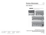
Digital Display Scaler
1
Chapter One
Introduction
About this Manual
About the Scaler
Features

Introduction, cont’d
Digital Display Scaler • Introduction1-2
Introduction
About this Manual
This manual contains installation, configuration, and operating information for the
Extron DDS 402 digital display scaler.
This chapter identifies the scaler’s features. Chapter 2 details how to install the
scaler. Chapter 3 describes how to operate the scaler and use all of its features.
Chapter 4 provides information about programming the scaler under RS-232
control, such as from a PC or a host controller. Chapter 5 details the Extron control
software for Windows, which allows you to operate the scaler from a PC in a
graphical environment. Appendix A lists the scaler’s specifications and pertinent
part numbers and provides procedures for performing updates and repairs.
About the Scaler
The DDS 402 is a two-input digital display scaler (figure 1-1). The scaler inputs
high-resolution RGBHV/RGBS/RGsB video on a 15HD connector (Input 1) and
either RGBHV/RGBS/RGsB video or component video signals on five BNC
connectors (Input 2). Input 1 is buffered, looped through, and output on a 15HD
connector for use by a local monitor. The DDS 402 scales the selected input up or
down to any 1 of 41 output resolutions and rates and outputs the video as both
RGBHV or RGBS video and HD component video, on five BNCs and a 15HD
connector. Several of the output resolutions and rates include Extron’s Accu-RATE
Frame Lock™ (AFL™), a proprietary technology that locks the output frame rate to
the input rate, solving the problems that result from different input and output
rates. For home theaters, the DDS 402 features HDTV 720p, 1080p, and 1080i
outputs.
Extron
DDS 402
2A
M
A
X
100-24
0V
50-60H
z
R
E
M
O
T
E
R
G
B
/
H
D
R
-
Y
,
B
-
Y
,
Y
R
G
B
/
R
-
Y
,
B
-
Y
,
Y
R
G
B
R
G
B
/
R
-
Y
,
B
-
Y
,
Y
2
1
R
/
R
Y
G
/
Y
B
/
B
-
Y
H
V
S
R
/
R
Y
G
/
Y
B
/
B
-
Y
H
V
S
O
U
T
P
U
T
S
I
N
P
U
T
S
HD Camera
PC Computer
RS-232
Control
Projector
Plasma
Display
Figure 1-1 — DDS 402 digital display scaler
For upscaling, the DDS 402 converts the horizontal and vertical sync timing and
the number of lines of the lower-resolution RGB input to match the native
resolution of the display. This produces an undistorted, brighter picture.
For downscaling, the DDS 402 accepts any computer resolution, up to 1600 x 1200,
with horizontal scan rates up to 100 kHz and vertical scan rates up to 120 Hz, and
converts the input to match the native resolution of the display.
The scaler is ideal for displaying images on projectors with limited display
resolutions, such as liquid-crystal display (LCD) projectors, digital light processor
(DLP) projectors, and plasma projectors.

1-3Digital Display Scaler • Introduction
The scaler also features a zoom function, up to 200%, that maintains the original
aspect ratio. The zoom function makes the scaler ideal for video wall applications
using four displays and four DDS 402s zoomed to 200%.
The scaler features four levels of horizontal filters, which help prevent detail loss,
and ten levels of vertical filtering, which reduce flicker.
Other picture controls that the DDS 402 provides are centering, size, brightness,
and contrast adjustments. The scaler also has a top and bottom line blanking
function.
The DDS 402 is housed in a rack-mountable, 1U high, 17.5" wide metal enclosure.
With the included mounting brackets, the scaler can be rack mounted, or mounted
under a desk or table, or against a wall or the side of a desk. The DDS 402 has an
internal 100VAC to 240VAC, 50/60 Hz, 30 watts auto-switchable power supply that
provides worldwide power compatibility.
Features
Inputs — The DDS 402 switches between two inputs: Input 1 accepts computer
video on a 15HD connector, Input 2 accepts high resolution RGBHV, RGBS,
RGsB, or component video on five BNCs.
Computer video loop-through connector — The computer video input, Input 1, is
buffered, looped through, and output for use on a local monitor on a 15HD
connector.
Outputs — The DDS 402 scales images to the following output resolutions:
• 640 x 480 (VGA) at 50 Hz, 60 Hz, 75 Hz, and lock*
• 800 x 600 (SVGA) at 50 Hz, 60 Hz, 75 Hz, and lock*
• 832 x 624 (Macintosh) at 60 Hz and 75 Hz, and lock*
• 848 x 480 (plasma) at 60 Hz and lock*
• 852 x 480 (plasma) at 60 Hz and lock*
• 1024 x 768 (XGA) at 50 Hz, 60 Hz, 75 Hz, 85 Hz, and lock*
• 1280 x 768 (plasma) at 56 Hz and lock*
• 1280 x 1024 (SXGA) at 50 Hz, 60 Hz, and lock*
• 1360 x 765 (plasma) at 60 Hz and lock*
• 1365 x 1024 (plasma) at 60 Hz and lock*
• 1400 x 1050 (SXGA+) at 50 Hz, 60 Hz, and lock*
• 576p (HDTV) at 50 Hz and lock*
• 720p (HDTV) at 60 Hz and lock*
• 1080p (HDTV) at 60 Hz and lock*
• 1080i (HDTV) at 50 Hz, 60 Hz, and lock*
* See Accu-RATE Frame Lock (patent pending) below.

Introduction, cont’d
Digital Display Scaler • Introduction1-4
Operational flexibility — Operations such as input and scaling selection, picture
controls, and saving and recalling of presets can be performed on the front
panel or over the RS-232 link. The RS-232 link allows remote control via a PC
or control system. Input selection is also available under contact closure
control.
• Front panel control — The scaler front panel controller supports individual
input selection. The front panel features large, positive touch, illuminated
buttons that can be labeled with text or graphics, two rotary knobs for
making adjustments or selecting menu options, and an LCD.
• Windows-based control program — Extron’s Windows-based control
program provides a versatile range of operational options with its graphical
interface and drag-and-drop/point-and-click operation.
• Simple Instruction Set (SIS™) control — The remote control protocol uses
Extron’s SIS for easy programming and operation.
• Contact closure control — The operator can select either input via contact
closure through the Remote port.
Accu-RATE Frame Lock™ (AFL™) — A technology exclusive to Extron that solves
frame rate conversion issues experienced by video scalers. When video input
and output refresh rates differ, occasionally the two rates cross over each
other. The result is a glitch or image freeze on the display. AFL solves this
problem by locking the output frame rate to the input frame rate.
3:2 pulldown detection for NTSC video sources — This advanced, patent pending,
film mode processing feature helps maximize image detail and sharpness for
video sources that originated from film. When film is converted to NTSC
video, the film frame rate has to be matched to the video frame rate in a
process called 3:2 pulldown. Jaggies and other image artifacts can result if
conventional deinterlacing techniques are used on film-source video. The
DDS 402’s advanced film mode processing recognizes signals that originated
from film. The DDS 402 then applies video processing algorithms that
optimize the conversion of video that was made with the 3:2 pulldown
process. This results in richly detailed images with sharply defined lines.
Test patterns — The switcher features built-in test patterns to aid in monitor or
projector set-up and evaluation.
Blue mode — The switcher can be set to output the blue video signal only, to help
installers calibrate the monitor or projector.
Triple-Action Switching™ (RGB delay) — RGB delay blanks the screen when the
scaler switches between inputs. The new sync signals precede the RGB
signals, so that a noise-filled scramble is not shown during the transition.
The time delay between the RGB and sync signals is user adjustable up to
five seconds on the front panel and under RS-232 control.
Horizontal and vertical detail — The DDS 402 offers four levels of horizontal detail
and eight levels of vertical detail. Horizontal and vertical detail minimize the
loss of picture fidelity.
Picture controls — Horizontal and vertical centering, horizontal and vertical sizing,
brightness, contrast, zoom, and detail controls are available for fine picture
adjustments.
Top and bottom line blanking — Extron’s exclusive variable horizontal blanking
feature allows the operator to add black lines at the top and bottom edges of
the image to mask the top and bottom each image.

1-5Digital Display Scaler • Introduction
Freeze mode — Locks the output display to the selected image. Once an input is
frozen, the input can be removed without losing the output image. This
feature lets the DDS 402 function as a still store.
Auto memories — The two inputs support 32 auto-recall memories each, based on
the incoming frequency. Information on sizing, centering, detail, contrast,
and brightness is saved.
Front panel security lockout — Locks out all front panel functions except the input
selection and centering controls. When the front panel is locked, all functions
are still available via RS-232 commands.
Mounting flexibility — Mounting brackets make the 1U high scaler mountable in
any conventional 19” wide rack, or under or through a desk or other
furniture.
Power — The 100VAC to 240VAC, auto-switchable, internal power supply of the
DDS 402 provides worldwide power compatibility.

Introduction, cont’d
Digital Display Scaler • Introduction1-6

Digital Display Scaler
2
Chapter Two
Installation
Installation Overview
Mounting the Scaler
Cabling and Rear Panel Views
Configuration

Installation, cont’d
Digital Display Scaler • Installation2-2
Installation
Installation Overview
To install and set up a DDS 402 Digital Display Scaler for operation, perform the
following steps:
1
Disconnect power from all of the equipment, including the video source(s),
and the devices that will receive the scaled video signal.
2
Rack mount the scaler, if desired. See Mounting the Scaler in this chapter.
3
Connect the digital input and loop-through cables. See Video input connections
in this chapter.
4
Connect the digital output cables. See Video output connections in this chapter.
5
If desired, connect the RS-232 cable. See RS-232 connection and Contact closure
connection in this chapter.
6
Connect the AC power cable. See Power connection in this chapter.
Mounting the Scaler
The DDS 402 comes with rubber feet and a set of rack mounting brackets.
Tabletop use
For tabletop use, attach a self-adhesive rubber foot to each corner of the bottom of
the DDS 402 scaler.
Rack mounting
Rack mount the scaler as follows:
1. Attach the rack mount brackets to the scaler with eight #8 machine
screws, provided (figure 2-1).
2. Insert the scaler into the rack, align the holes in the mounting bracket
with those of the rack.
2A MAX
100-240V 50-60Hz
REMOTE
RGB/HD R-Y, B-Y, Y
RGB/R-Y, B-Y, Y
RGB
RGB/R-Y, B-Y, Y
2
1
R
/RY
G
/Y
B
/B-Y
H
V
S
R
/RY
G
/Y
B
/B-Y
H
V
S
O
U
T
P
U
T
S
I
N
P
U
T
S
Rack-mount
Bracket
Figure 2-1 — Mounting the digital display dcaler
3. Secure the scaler to the rack using the supplied machine screws.
Cabling and Rear Panel Views
All connectors are on the rear panel (figure 2-2).

2-3Digital Display Scaler • Installation
2A MAX
100-240V 50-60Hz
REMOTE
RGB/HD R-Y, B-Y, Y
RGB/R-Y, B-Y, Y
RGB
RGB/R-Y, B-Y, Y
21
R
/R-Y
G
/Y
B
/B-Y
HVS
R
/R-Y
G
/Y
B
/B-Y
H
/HV
V
O
U
T
P
U
T
S
I
N
P
U
T
S
1
2
7 53 64
Figure 2-2 — DDS 402 rear panel connectors
Video input connections
1
Input 1 (computer video) input (top) connector — Connect computer or RGB
video to this female 15HD connector.
2
Input 1 (computer video) loop-through (bottom)
connector — Connect a local monitor to this female 15HD
connector. The scaler buffers the computer video input
and loops it on this connector.
The Digital Display Scaler buffers the computer video input signal before
passing it to the loop-through connector. Beyond that, it does not alter the
loop-through video in any way. The loop through output is the same
resolution and frequency as the computer video input.
3
Input 2 (RGB or component video) connectors — Connect RGBHV, RGBS,
RGsB, or component video (R-Y, Y, B-Y for YUVi or YUVp, or Betacam) to
these female BNC connectors (figure 2-3).
Ensure that the correct Input 2 video format is selected from the front panel
menu, see Input #2 submenu, in chapter 3, Operation, or via the RS-232
port, see chapter 4, Programmer’s Guide, and chapter 5, Scaler Software.
R
/R-Y
G
/Y
B
/B-Y
R
/R-Y
G
/Y
B
/B-Y
H
/HV
V H
/HV
V
R
/R-Y
G
/Y
B
/B-Y
H
/HV
V
RGBHV video
RGBS video
RGsB video Component video (R-Y, B-Y, Y)
R
/R-Y
G
/Y
B
/B-Y
H
/HV
V
Figure 2-3 — Input 2 connections for RGBHV, RGBS, RGsB and
component video
For RGBHV video — Connect to five BNC connectors.
For RGBS video — Connect to four BNC connectors.
For RGsB and component video — Connect to three BNC connectors.
Video output connections
The two video output connectors, the 15HD connector and the five BNC
connectors, both output the same video signal. The 15HD connector outputs
RGBHV only, not RGBS.
4
RGB/HD R-Y, B-Y, Y Output 15HD connector — Connect an RGB video or
HD component video display to this female 15HD connector.
RGB
1

Installation, cont’d
Digital Display Scaler • Installation2-4
5
RGB/HD R-Y, B-Y, Y Output BNC connectors — Connect an RGB video or
HD component video display to these female BNC connectors (figure 2-4).
VH
RGBHV video
RGBS video
Component video (R-Y, B-Y, Y)
S
S
HV
R
/R-Y
G
/Y
B
/B-Y
R
/R-Y
G
/Y
B
/B-Y
VH
S
R
/R-Y
G
/Y
B
/B-Y
Figure 2-4 — BNC output connections for RGBHV, RGBS, and component
video
For RGBHV video — Connect to five BNC connectors.
For RGBS video — Connect to four BNC connectors.
For component video — Connect to three BNC connectors.
RS-232 connection
6
Remote port — Connect a host device, such as a computer or touch panel
control, to the Digital Display Scaler via this 9-pin D connector for serial
RS-232 control (figure 2-5).
Female
51
96
Male
15
69
RS-232 FunctionPin
1
2
3
4
5
6
7
8
9
—
TX
RX
—
Gnd
—
—
—
—
Contact closure, input #1
Transmit data
Receive data
Contact closure, input # 2
Signal ground
Not used
Not used
Not used
Not used
Figure 2-5 — Remote port pin assignments
See chapter 4, Programmer’s Guide, for definitions of the SIS commands and
chapter 5, Scaler Software to install and use the control software.
Contact closure connection
6
Remote port — The Remote connector also provides a way to select an input
using a remote contact closure device. Contact closure control uses pins on
the Remote connector that are not used by the RS-232 interface (figure 2-5).
To select a different input number using a contact closure device, momentarily
short the pin for the desired input number to logic ground (pin 5). To force
one of the inputs to be always selected, leave the short to logic ground in
place. The short overrides front panel input selections.
Power connection
7
AC power connector — Plug a standard IEC power cord into this connector
to connect the scaler to a 100 to 240VAC, 50 Hz or 60 Hz power source. The
front panel control and input selection buttons light in sequence during
power-up, the LCD displays the product name and then cycles through the
default messages.
Configuration
DDS 402 can be configured using either the front panel controls, the SIS, or the
Windows Control program. See chapter 3, Operation, chapter 4, Programmer’s Guide,
and chapter 5, Scaler Software for more information.
/