Page is loading ...

Q-Zone Hoop-Frame
Assembly Instructions
Copyright November 2, 2018
Grace Company
(Reproduction Prohibited)
Version 2.0

Table of Contents .....................................................................................................................i
Warranty .................................................................................................................................. ii
Parts List
Box 1 .........................................................................................................................................iii
Box 2 ....................................................................................................................................... iv
Box 3 ........................................................................................................................................ iv
Assembly Instructions
Step 1: Right Leg Setup ...............................................................................................................1
Step 2: Left Leg Setup .................................................................................................................3
Step 3: Frame Cross Support Installation ......................................................................................5
Step 4: Front Long Rail Installation ...............................................................................................6
Carriage Installation
Step 5: Carriage Assembly ...........................................................................................................7
Step 6: Carriage Installation .........................................................................................................8
Machine Installation
Step 7: Sewing Machine Installation .............................................................................................9
Step 8: Machine Installation .......................................................................................................10
Assembly
Step 9: Long Back Rail Installation..............................................................................................11
Setup
Step 10: Basic Setup .................................................................................................................13
Fabric Setup
Fabric Setup .............................................................................................................................. 15
Step 11: Making Leader Cloths ...................................................................................................16
Step 12: Fabric Installation ........................................................................................................ 17
Care and Use ..........................................................................................................................19
Table of Contents
i

?
Warranty
1-800-264-0644
Warranty Information for your Q-Zone Hoop-Frame
Quilting Frame
The Q-Zone Hoop-Frame Quilting Frame has a One-Year limited warranty on all parts.
The Grace Company will repair or replace, at its discretion, any part with problems
due to our manufacturing or defects in materials. This warranty does not cover parts
damaged through misuse, improper storage, improper assembly, loss, natural events,
and willful destruction. Parts must be returned to the Grace Company, shipping
prepaid, before we can repair or replace them. We will promptly return the repaired/
replaced part at our expense if done within a year of the purchase date.
ii

Corner Brace (4) Bungee Mount (4) M6 x 10mm Connector
Bolt (16)
10mm & 13mm Box
End Wrench (1)
3mm Allen Wrench (1) 4mm Allen Wrench (1)
14
17
|Parts List Q-Zone Hoop-Frame
Side Fabric Clip (2)
Part List
Box 1
Right Leg Assembly (1)
Left Leg Assembly (1)
14mm & 17mm Box
End Wrench (1)
Bungee Clamp
Assembly (4)
Bungee Stop (4)
iii

|Parts List Q-Zone Hoop-Frame
Front Long Rail (1)
Back Long Rail (1)
Table Support Assembly (2)
Front Fabric Clip (2)
Fabric Clip (3)
Box 2
Box 3
Carriage (1)
Carriage Channel Lock
(1)
Sewing Machine
Channel Lock (1)
Channel Lock Washer
(1)
M6 x 20mm SBHCS
(1)
iv

Centering
Screws
Height
Screws
Nut
Nut
Washer
Washer
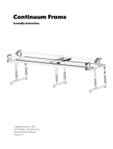
1-3 Remove height screws and loosen centering
screws.
1-2 Extend to the rst slot for machines with throat
less than 16”.
Extend to the second slot for machines with throat
greater than 16”.
Right Leg
Assembly (1)
Corner Brace (2)
M6 x 10mm
Connector Bolt (4)
Step 1 – Right Leg Setup
Parts Needed:
Tools Needed:
3mm Allen Wrench
4mm Allen Wrench
10mm & 13mm Box End Wrench
1-1 Loosen the (2) M6 x 10 Set Screws.
Loosen Set
Screws
3mm Allen
Wrench
|Assembly Q-Zone Hoop-Frame
Second Slot
First Slot
1

1-4 Adjust table height by sliding legs up or down
using the chart to the right for your desired height.
1-5 Replace each height screw and tighten each
centering screw.
Hole
Number
Floor to Top of
Fabric
1 31 Inches
2 32 Inches
3 33 Inches
4 34 Inches
5 35 Inches
6 36 Inches
7 37 Inches
8 38 Inches
9 39 Inches
10 40 Inches
Note: Height will vary slightly after adjusting
Leveling Feet in Step 10-1.
Centering
Screws
Height
Screws
Nut
Nut
Washer
Washer
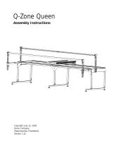
1-6 Install (2) Corner Braces with the tabs toward
the inside of the leg using (4) M6 x 10mm Connector
Bolts.
Note: Leave M6 x 10mm Connector Bolts loose so
that you may align the adjoining parts.
M6 x 10mm
Connector Bolt
M6 x 10mm
Connector Bolt
Corner Brace
|Assembly Q-Zone Hoop-Frame
Hole
Number 1
Corner Brace
Note Tab
Orientation
2

Centering
Screws
Height
Screws
Nut
Nut
Washer
Washer
2-3 Remove height screws and loosen centering
screws.
2-2 Extend to the rst slot for machines with throat
less than 16”.
Extend to the second slot for machines with throat
greater than 16”.
Left Leg
Assembly (1)
Corner Brace (2)
M6 x 10mm
Connector Bolt (4)
Step 2 – Left Leg Setup
Parts Needed:
Tools Needed:
|Assembly Q-Zone Hoop-Frame
2-1 Loosen the (2) M6 x 10 Set Screws.
Loosen Set
Screws
3mm Allen
Wrench
Second Slot
First Slot
3mm Allen Wrench
4mm Allen Wrench
10mm & 13mm Box End Wrench
3

2-5 Replace each height screw and tighten each
centering screw.
2-4 Adjust table height by sliding legs up or down
using the chart to the right for your desired height.
Hole
Number
Floor to Top of
Fabric
1 31 Inches
2 32 Inches
3 33 Inches
4 34 Inches
5 35 Inches
6 36 Inches
7 37 Inches
8 38 Inches
9 39 Inches
10 40 Inches
Centering
Screws
Height
Screws
Nut
Nut
Washer
Washer
Hole
Number 1
M6 x 10mm
Connector Bolt
M6 x 10mm
Connector Bolt
Corner Brace
|Assembly Q-Zone Hoop-Frame
Note: Height will vary slightly after adjusting
Leveling Feet in Step 10-1.
Note Tab
Orientation
Corner Brace
2-6 Install (2) Corner Braces with the tabs toward
the inside of the leg using (4) M6 x 10mm Connector
Bolts.
Note: Leave M6 x 10mm Connector Bolts loose so
that you may align the adjoining parts.
4

3-3 Press the Right and Left Legs tight against the
Table Support Assemblies and tighten the (16) M6
x 10mm Connector Bolts.
3-1 Install a Table Support Assembly to the Right
and Left Legs using (4) M6 x 10mm Connector
Bolts.
Note: Leave Bolts loose so that you may align the
adjoining parts. Track should be to the outside of
the Frame.
3-2 Install the second Table Support Assembly
to the Right and Left Legs using (4) M6 x 10mm
Connector Bolts.
Note: Leave Bolts loose so that you may align the
adjoining parts. Track should be to the outside of
the Frame.
Table Support
Assembly (2)
M6 x 10mm
Connector Bolt (4)
Step 3 – Frame Cross Support Installation
Parts Needed:
Tools Needed:
4mm Allen Wrench
M6 x 10mm
Connector Bolt
Table Support
Assembly
Table Support
Assembly
M6 x 10mm
Connector Bolt
M6 x 10mm
Connector Bolt
Note Track
Orientation
Note Track
Orientation
|Assembly Q-Zone Hoop-Frame
5

Front Long Rail (1)
Step 4 - Front Long Rail Installation
Parts Needed:
Tools Needed:
4mm Allen Wrench
4-1 Remove the (2) M6 x 40mm SBHCS from the
Right Front Corner.
M6 x 40mm
SBHCS
Front Corner
4-3 Install the Front Long Rail with the larger holes
up. Reinstall the Front Corners using the (4) M6 x
35mm SBHCS removed in previous steps.
Front Corners
M6 x 35mm
SBHCS
Front Long Rail
4-2 Remove the (2) M6 x 40mm SBHCS from the
Left Front Corner.
M6 x 40mm
SBHCS
Front Corner
|Assembly Q-Zone Hoop-Frame
Large Holes
6

Carriage (1)
Carriage Channel
Lock (1)
Step 5 - Carriage Assembly
Parts Needed:
5-1 Remove the right rear M6 x 20mm SBHCS
Wheel and Spacer from the Carriage.
M6 x 20mm
SBHCS
Wheel
Tools Needed:
4mm Allen Wrench
|
Carriage Installation
Q-Zone Hoop-Frame
5-2 Install the Carriage Channel Lock, as shown,
making sure the spacer is between the Wheel and
the Wheel Extrusion.
Note: Leave M6 x 20mm SBHCS loose.
M6 x 20mm
SBHCS
Carriage
Channel Lock
Spacer
Wheel Spacer
5-3 Slide the Carriage Channel Lock against the
Wheel Extrusion and tighten the M6 x 20mm
SBHCS from step 5-2. See page 13 for Channel
Lock adjustments.
Carriage
Channel Lock
Wheel
Extrusion
7

6-2 Loosen the (4) M6 Connector Bolts for the
Back Track Assembly.
M6 Connector
Bolt
6-3 Slowly move the Carriage from one end of the
Track to the other, tightening each of the (4) M6
Connector Bolts as you go.
6-1 Place the Carriage onto the Track.
Note: Make sure the Channel Lock is in the open
position.
6-4 It may be necessary to adjust the rear carriage
wheels. Loosen the (2) M6 Connector Bolts and
adjust the Carriage to t to the track.
M6 Connector
Bolt
Step 6 - Carriage Installation
M6 Connector
Bolt
|
Carriage Installation
Q-Zone Hoop-Frame
8

Sewing Machine
Channel Lock
M6 x 20mm
SBHCS
M6 x 16mm
SBHCS
Parts Needed:
Step 7 - Sewing Machine Installation
Sewing Machine
Channel Lock (1)
7-1 Remove right rear M6 x 16mm SBHCS from the
Sewing Machine.
7-2 Install Sewing Machine Channel Lock onto
Sewing Machine using (1) M6 x 20mm SBHCS and
(1) Channel Lock Washer as shown. See step 10-3
for Channel Lock adjustments.
M6 x 20mm
SBHCS (1)
Machine Installation
Tools Needed:
4mm Allen Wrench
|
Q-Zone Hoop-Frame
Channel Lock
Washer
Channel Lock
Washer (1)
9

Step 8 - Machine Installation
Machine Installation
|
Q-Zone Hoop-Frame
8-1 Place the Sewing Machine onto the Carriage.
8-2 It may be required to adjust the spacing on
the Sewing Machine wheels to t the Carriage.
Loosen the M6 Set Screw on the Wheel Assembly
and adjust to t.
Note: Wheel covers may have to be removed for
this step.
Tools Needed:
3mm Allen Wrench
M6 Set Screw
10

Back Long Rail (1)
Parts Needed:
Back Corner Cover
Left
Back Corner
Cover Right
M6 x 30mm
Thumb Screw
Back Long Rail
9-2 Install the Back Long Rail. Reinstall the Back Corner Right and Left Covers using (6) M6 x 30mm
Thumb Screws removed in the previous step.
Note: It may be required to raise the Hoop Assembly. See Steps 9-3 and 9-4.
M6 x 30mm
Thumb Screw
9-1 Remove the (6) M6 x 30mm Thumb Screws
from the right and left Back Corner Covers and
remove the Back Corner Covers.
M6 x 30mm
Thumb Screws
Back Corner Right
Cover
Note orientation of the
Back Long Rail
Step 9 - Back Long Rail Installation
|Assembly Q-Zone Hoop-Frame
Note orientation of the
fabric holders
Tools Needed:
3mm Allen Wrench
11

Hoop Adjustment
Take-Up Lever
Front Long Rail
Needle Plate
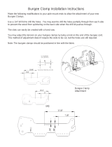
9-4 Adjust the Rail Height by pushing in on the
(2) Hoop Adjustment Take-Up Levers and raise or
lower the Front Long Rail so the top of the Front
Long Rail and the Sewing Machine Needle Plate
are level
M6 x 10mm Set Screw
9-5 Adjust the Rail Height by pushing in on the (2) Hoop Adjustment Take-Up Levers and raise or lower
the Back Long Rail so there is approximately 1/4” gap between the bottom of the fabric and the bottom
of the Sewing Machine Throat. Tighten the (4) M6 Set Screws From Step 9-3.
Hoop Adjustment
Take-Up Lever
Back Long Rail
Sewing Machine
Throat
Hoop Adjustment
Take-Up Lever
1/4” Gap
9-3 Loosen the M6 x 10mm Set Screws on each of
the (4) Hoop Support Outer Tubes.
|Assembly Q-Zone Hoop-Frame
12

Setup
|
Q-Zone Hoop-Frame
Step 10 - Basic Setup
Leveling Foot
Lower table
Raise table
Tools Needed:
3mm Allen Wrench
10mm/13mm Box End Wrench
14mm/17mm Box End Wrench
10-1 Adjust the Leveling Feet to level the frame
and make sure it is stable. Adjust so the Carriage
and Machine do not move on their own.
10-2 Slide the Bungee Mounts onto the Bungee
Mount Holder.
Bungee
Mount Holder
Bungee Mount
13

Setup
|
Q-Zone Hoop-Frame
10-3 Rotate the Channel Lock handle down. To adjust the Channel Lock, loosen the 4mm upper Hex
Nut. Twist the Rubber Foot clockwise until it is snug against the track. Turn the 4mm upper Hex Nut
counterclockwise until it is snug against the Channel Lock barrel.
Note: Channel Locks are used to lock the Sewing Machine, or the Carriage to assist in straight line
stitching.
4mm Hex
Nut
10-4 Rotate the Channel Lock handle down. To adjust the Channel Lock, loosen the 4mm upper Hex
Nut. Twist the Rubber Foot clockwise until it is snug against the track. Turn the 4mm upper Hex Nut
counterclockwise until it is snug against the Channel Lock barrel.
Note: Channel Locks are used to lock the Sewing Machine, or the Carriage to assist in straight line
stitching.
4mm Hex
Nut
14

1. Cut your Backing 6 inches larger in all directions than your Quilt Top. Cut your Batting 4 inches
larger in all directions than your Quilt Top.
2. Find the center on your Back Rail Cloth Leader and Front Rail Cloth Leader and mark it. Find the
center on your Backing on both the front and back rail edges and mark it. Lay the Backing with the
visible side down on a clean surface.
3. Match the center of each Cloth Leader with each center mark on the Backing and pin or baste
from the center out to the end of the leader on both sides. Be sure there are no gaps between the
pins.
4. Find the center on your Batting on both the front and back rail edges and mark it. Lay your Batting
centered on top of your Backing with the center marks aligned.
5. Pin the Batting to the Backing from the center out.
6. Find the center on your Quilt Top on both the front and back rail edges and mark it. Lay your Quilt
Top centered on top of your Batting with the center marks aligned.
7. Pin the Quilt Top to the Batting from the center out.
8. Roll each layer up separately starting with the Quilt Top toward the Back Rail Cloth Leader. Leave
about 2 feet unrolled.
9. Roll your sewing machine to the far left and back side of the frame.
10. Lay your rolled fabric across the two rails to the right of the sewing machine with the Back Rail
Cloth Leader draping over the back rail of the frame.
11. Pull the fabric through the throat of the machine and under the presser foot.
12. Utilize the machine to assist with fabric positioning and alignment. Roll the sewing machine
on the carriage as far back as you can. Then position the fabric so that the Quilt Top edge is
approximately 1 inch away from the needle. While gliding the sewing machine across the frame
check that the Quilt Top continues to be 1 inch away from the needle.
Fabric Setup
15
/