Page is loading ...

Pg. 1
Copyright May 15, 2011
GraceWood, Inc
(Reproduction Prohibited)
Revision 3
Quilting Frame
With Dual-Wheel Carriage and Rigid-Rail Design

Pg. 2
Quilting Frame
Parts List
Box 1 ..................................................3
Box 2 ..................................................4
Plastic Parts List ...........................................5
Hardware List .............................................6
Carriage Parts List. . . . . . . . . . . . . . . . . . . . . . . . . . . . . . . . . . . . . . . . . . 7
Assembly Steps
Step 1- Height Adjustable Leg Assembly ..........................7
Step 2- Side Leg Assembly ...................................7
Step 3- Middle Leg Assembly ..................................8
Step 4- Track Support Assembly ................................8
Step 5- Table Brace Assembly .................................9
Step 6- Table Support Assembly ................................10
Step 7- Table Assembly ......................................10
Step 8- Track Assembly ......................................10
Step 9- Frame End Assembly ..................................11
Step 10- Shelf Support Assembly ...............................12
Step 11- Take-Up Rail Bracket Assembly ..........................13
Step 12- Bungee Brace Assembly ...............................13
Step 13- Front Rail Mount End Assembly ..........................14
Step 14- Shelf Assembly .....................................14
Step 15- Rail Assembly ......................................15
Step 16- Rail to Frame Assembly ...............................16
Step 17- Carriage to Frame Assembly ............................16
Pattern Perfect Bracket ......................................17
Adjusting Your Bottom Plate ..................................17
Laser (Optional Accessory) ...................................17
Fabric Installation
Fabric Installation ..........................................18
Step 1- Batting ............................................19
Step 2- Quilt Top to Quilt Top Rail ..............................19
Step 3- Quilt Backing to Backing Rail ............................20
Step 4- Attaching Quilt Layers to the Take-Up Rail ...................20
Rolling your Fabric .........................................21
Turning you Quilt Around .....................................21
Making Cloth Leaders .......................................22
Bungee Clamp Instructions ...................................23
Gracie Laser User Manual ....................................24
Welcome!
As you begin assembly of your new home machine quilting system, keep in mind the following:
1: The assembly process will be simple and step by step.
2: Read through each step completely before beginning that step.
3: Using the parts list as a reference, take the parts out of the box and make sure that you have
them all.
4: Identify hardware packets: All hardware is separated by type and each packet is labeled for
easeinidentication.
5: If anything appears to be missing or damaged please contact your dealer or the Grace
Company directly at 1-800-264-0644 or info@graceframe.com.

Pg. 3
Box 1
Shelf Support (4)
Front Track Support (2)
Back Track Support (2)
Shelf (2)
Table (2)
Rail (8)
60” Plastic Track (4)
Front Top Track Support(2)
Right Frame End (1)
Left Frame End (1)

Pg. 4
Box 2
Right Bungee Clamp Brace (1)
Left Bungee Clamp Brace (1)
Left Track Brace (1)
Right Track Brace (1)
Middle Lower Leg Brace (1)
Middle Track Brace (1)
Take-Up Rail Bracket Right (1)
Left Front Rail Mount End (1)
Table Support (6)
Right Lower Leg Brace (1)
Left Lower Leg Brace (1)
Short Leg (4)
Long Leg (2)
Shelf Support
Connector (4)
Rail Coupler (4)
Back Track Support
Coupler (1)
Front Track Support
Coupler (1)
Right Front Rail Mount End (1)
Take-Up Rail Bracket Left (1)
120” Plastic Track (4)
116” Plastic Tubing (4)
Table Brace (4)

Pg. 5
Plastic Parts List
(Box 2 continued)
Right Frame
Corner
(1)
Left Frame
Corner
(1)
Ratchet
Wheel
(6)
Ratchet Wheel
Holder
(2)
Fourth Rail
End Cap
(2)
Bungee Clamps
(4)
Fabri-Fast Tool
(1)
4th Rail Insert
Washer
(2)
Laser
(1)
Sewing
Machine
Clamp
(4)

Pg. 6
Hardware List
(Box 2 continued)
M6 x 25mm Socket Button
Head Cap Screw (SBHCS)
(4)
M6 x 10mm Socket Button
Head Cap Screw (SBHCS)
(110)
M3 Allen Wrench
(1)
M13/M10
Box End Wrench
(1)
M6 Hex Nut
(6)
M4 Allen Wrench
(1)
Steel Spacer
(4)
Warranty Information
for your Grace Machine Quilting Frame
The Machine Quilting Frame has a One-Year limited warranty on all parts. The Grace Company
will repair or replace, at its discretion, any part with problems due to our manufacturing, or defects in
materials. This warranty does not cover parts damaged through misuse, improper storage, improper
assembly, loss, natural events, or willful destruction. Parts must be returned to the Grace Company,
shipping prepaid, before we can repair or replace them.
M6 x 30mm Socket
Button Head Cap Screw
(SBHCS) (8)
M6 X 10mm Set
Screw
(8)
M5 X 16mm Socket Button
Head Cap Screw (SBHCS)
(24)
M6 X 16mm Socket Button
Head Cap Screw (SBHCS)
(8)
M6 x 35mm Socket
Button Head Cap Screw
(SBHCS) (4)
M8 Hex Nut
(4)
M8 Eye Bolt
(2)

Pg. 7
Carriage Top Plate (1)
Carriage Bottom Plate (1)
Carriage Parts
(Box 2 continued)
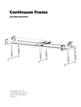
Step 1: Height Adjustable Leg - Assembly
Parts Needed:
4-Short Leg
2-Long Leg
Leveling
Foot
Height
Adjustable
Leg
1-1: Unscrew a M6 X 55mm SBHCS from a leg and slide the height
adjustable leg to the desired height. Then slide the SBHCS back into the
Height Adjustable Leg and out the other end. Slide a washer on the end
ofthescrewandtightenanutontotheendofthescrew.Followthisstepagainfortheotherve
legs. Make sure all the legs are at the same height.
Fig. 1-1
M6 x 55mm
SBHCS
M6 Nylock Nut
7mm Washer
Height of Fabric Surface
Top Hole 45” 4th Hole 41”
7th Hole 44” 3rd Hole 40”
6th Hole 43” 2nd Hole 39”
5th Hole 42” Bottom Hole 38”
Pattern Perfect Bracket (1)
Non Skid Pad (1)
Step 2: Side Leg - Assembly
Parts Needed:
24-M6 x 10mm SBHCS
1-Right Track Brace
1-Left Track Brace
1-Right Lower Leg Brace
1-Left Lower Leg Brace
2-Short Leg
2-Long Leg
Note: Do not completely tighten the screws in
this step until the end of Step 8.
Note: Make sure the side of the leg with (4) holes
faces the outside of the frame.

Pg. 8
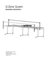
2-1: Slide the Short Leg inside the opening at the end of
the Left Lower Leg Brace (side without the tab sticking out),
and fasten it in place with (4) M6 x 10mm SBHCS.
2-2: Attach the long leg to the left lower brace,
making sure the leg slides into the slot with the
tab sticking out using (4) M6 x 10mm SBHCS, as
shown in Fig. 2.1.
2-3: Attach the Left Track Brace to the short and
long legs on the opposite side of the Left Lower
leg brace tab with (4) M6 x 10mm SBHCS.
2-4: Repeat Steps 2-1 through 2-3 to
assemble the Right Leg.
Fig. 2-1
Left Lower
Leg Brace
Long Leg
Short Leg
Note: Skip this step if setting up in crib.
Note: Do not completely tighten the screws in this step
until the end of Step 8.
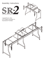
3-1: Attach the Middle Lower Leg Brace to the Middle Legs
with (8) M6 x 10mm SBHCS, as shown in Fig. 3-1. Make sure
that the side of the leg with no holes goes toward the inside.
3-2: Attach the Middle Track Brace to the Middle Legs with
(8) M6 x 10mm SBHCS.
Fig. 3-1
Middle Lower
Leg Brace
Short Leg
M6 x 10mm
SBHCS
Middle
Track Brace
Step 3: Middle Legs - Assembly
Parts Needed:
16-M6 x 10mm SBHCS
2-Short Leg
1-Middle Track Brace
1-Middle Lower Leg Brace
Left Track
Brace
M6 x 10mm
SBHCS
Face
outside
Tab
towards
the
long leg
No holes
Step 4: Track Support - Assembly
Parts Needed:
16-M6 x 10mm SBHCS
8-M6 x 10mm Set Screws
1-Left Leg Assembly
1-Right Leg Assembly
1-Middle Leg Assembly*
2-Front Track Support
2-Back Track Support
2-Front Top Track Support
1-Front Track Support Coupler
1-Back Track Support Coupler
*Note: If you’re setting the frame up in Crib Size you will
need to use both Side Legs, not the Middle Leg as shown in
Fig. 4-2b.

Pg. 9
Note: Skip steps 4-1 through 4-4, 4-7, 4-9, and 4-10 if setting up in crib size.
4-1: Slide the Back Track Support Coupler into the end of one Back Track Support with the two
holes near the end. Tighten (2) M6 x 10mm set screws
into the coupler through the Back Track Support, as
shown in Fig. 4-1a.
4-2: Slide the other Back Track Support onto the coupler
and tighten (2) M6 x 10mm Set Screws into the coupler
through the Back Track Support.
4-3: Follow Step 4-1 through 4-2 for the Track
Runnerandcoupler,asshowning4-1b(notuseduntil
step 7).
Note: The Front Track Support attaches to the diagonal
leg.
Fig. 4-1a
4-5: Attach the Back Track
Support to the outside holes on the Left Leg
Assembly with (2) M6 x 10mm SBHCS, as shown in
Fig. 4-2a.
4-6: Attach the other end of the Back Track
Support to the outside holes on the Right Leg with
(2) M6 x 10mm SBHCS.
4-7: Tighten (4) M6 x 10mm SBHCS, through the Back
Track Support and into the Middle Leg.
4-8: Attach the Front Track Support to the outside holes
on the Left Leg Assembly using (2) M6 x 10mm SBHCS
(if
setting up in crib, attach one end of the Front Track
Support to the Left Leg Assembly and the other end to
the Right Leg Assembly).
4-9: Attach the other side of the Front Track Support to
the inside holes on the Middle Leg with (2) M6 x 10mm
SBHCS.
4-10: Repeat Steps 4-8 through 4-9 for the other
Front Track Support.
M6 x 10mm
Set Screw
Track Runner
Coupler
Track Runner
Fig. 4-2a
M6 x 10mm
SBHCS
Front Track
Support
Back Track
Support
M6 x 10mm
SBHCS
Fig. 4-1b
Back Track
Support
Back Track
Support Coupler
Fig 4-2b
Note: Skip Steps 4-1 through 4-4, 4-7, 4-9, and 4-10 if
setting up in crib size.
4-1: Slide the Back Track Support Coupler into the end
of one Back Track Support with the two holes near the
end. Tighten (2) M6 x 10mm set screws into the coupler
through the Back Track Support, as shown in Fig. 4-1a.
4-2: Slide the other Back Track Support onto the coupler
and tighten (2) M6 x 10mm Set Screws into the coupler
through the Back Track Support.
4-3: Follow Step 4-1 through 4-2 for the Front Top
Track Support and coupler, as shown in Fig. 4-1b (not used
until step 7).
Note: The Front Track Support attaches to the diagonal
leg.
Step 5: Table Brace - Assembly
Parts Needed:
4-M6 x 10mm SBHCS
4-M6 x 35mm SBHCS
4-M6 Hex Nut
4-Table Brace
5-1: Attach (2) Table Brace to the left side of frame using (2)
M6 x 10mm SBHCS and to the track supports using (2) M6 x
25mm SBHCS and (2) M6 Hex Nuts, as shown in Fig. 5-1.
5-2: Repeat Step 5-1 for right side of the frame.
Fig 5-1
M6 x 10mm
SBHCS
M6 x35mm
SBHCS
M6 Hex Nut
Table Brace

Pg. 10
Step 6: Table Support - Assembly
Parts Needed:
12-M6 x 10mm SBHCS **(6 for Crib)
6-Table Support (King) **(3 for Crib)
6-1: Attach all (6) Table Supports to the Track
Supports using (2) M6 x 10mm SBHCS, as shown
in Fig. 6-1.
Note: ThescrewsgothroughtheTableSupportangerst
and then screw into the Track Support. The Table Support
endssitontopofthetrack’sangewiththetapesideup.
Step 7: Table - Assembly
Parts Needed:
2-Tables (King)** (1 for Crib)
7-1: Lay the Plastic Table on the Table Supports,
with the textured surface side UP, as shown in
Fig. 7-1.
7-2: Repeat Step 7-1 so that both Plastic Table
surfaces lay on the table assembly.
Note: The table should sit under the lip on the back
track support. Then will be held down by the lip on
the track runner in Step 8.
Fig. 7-1
Table
Step 8: Track - Assembly
Parts Needed:
1- Front Top Track Support Assembly
8- M6 X 10mm SBHCS* (4 for crib)
4-60” Crib Tracks*
4-120” King Tracks**
*For Crib setup only.
** For King setup only.
8-1: Insert (8) M6 X 10mm SBHCS
through the Front Track Support and into
the Front Top Track Support Assembly as
shown in Fig. 8-1. Do not tighten screws at
until Step 8-4.
Fig. 6-1
M6 X 10mm
SBHCS
Table Support
Track Runner
Assembly
M6 X 10mm
SBHCS
Fig. 8-1

Pg. 11
8-2: Slide two pieces of Track into the Back Track
Support, as shown in Fig. 8-2.
8-3: Slide two pieces of Track into the Front Top
Track Supports.
8-4: Use the Bottom Carriage to align the Front
Top Track Support, moving the carriage slowly
down the track, stopping at each screw to tighten
it in place, as shown in Fig. 8-3.
Step 9: Frame End - Assembly
Parts Needed:
8-M6 x 10mm SBHCS
4-M6 x 25mm SBHCS
1-Left Frame End
1-Right Frame End
1-Left Frame Corner
1-Right Frame Corner
4-Spacers
9-1: Slide a M6 x 25mm SBHCS through each of the
bottom holes in the Right Frame End and then slide a
spacer on the end of those screws, as shown in Fig. 9-1.
9-4: Follow Step 9-1 through 9-3 for the left side.
9-2: Tighten the screws into the bottom holes in the right legs.
9-3: Screw a M6 x 10mm SBHCS through the top holes of
the Right Frame End and Leg, as show in Fig. 9-2. Do not
completely tighten the screws at this time.
Fig. 9-1
Fig. 9-2
Spacer
Right Frame
End
Right Frame
Corner
M6 x 25mm
SBHCS
M6 x 10mm
SBHCS
Fig. 8-2
Track
Fig. 8-3

Pg. 12
Step 10: Shelf Support - Assembly
Parts Needed:
16-M6 x 10mm SBHCS (King) (8 for Crib)
4-Shelf Support (King) (2 for Crib)
4-Shelf Support Connectors (King)
8-M6 X 30mm SBHCS (King)
Fig. 10-1
M6 x 10mm
SBHCS
Shelf Support
Connectors
M6 x 10mm
SBHCS
Shelf Support
Fig. 10-2
10-1: Attach the Shelf Support Connector to the Shelf
Support by inserting (2) M6 X 10mm SBHCS through the
large holes in the shelf support connector and into the Shelf
Support, as shown in Fig. 10-1.
10-2: Attach the Shelf Support Connectors
to the Middle Lower Leg Brace by inserting
(2) M6 x 30mm SBHCS through the Shelf
Support and the Shelf Support Connector and
into the Middle Lower Leg Brace, as shown in
Fig. 10-2.
10-3: Attach the other end of the shelf
support to the Right Lower Leg Shelf Brace
with (2) M6 x 10mm SBHCS.
10-4: Follow Step 10-1 through 10-3 to
attach the last three (3) shelf supports to the
frame.
Note: For crib attach shelf supports to the
Right and Left Lower Leg Braces using (4)
M6x10mm SBHCS, as shown in Fig. 10-3.
Shelf
Support
9-5: Remove the two screws from the back corner of the right leg, as show in Fig. 9-1.
9-7: Thread the removed screws into the Right Frame Corner and through the Back Track Support
into the leg.
9-8: Follow Step 9-5 through 9-7 for the left side.
9-6: Place the Right Frame Corner over the Back Track Support and the Right Frame End.
Note: Completely tighten all the screws that were left loose in steps 2, 3 and 5. Make sure you
start at one end of the frame and work your way to the other end keeping your track supports lined
up as you go.
M6 x 30mm
SBHCS
Fig. 10-3

Pg. 13
Step 12: Bungee Brace - Assembly
Parts Needed:
4-M6 x 16mm SBHCS
4-M6 Hex Nuts
1-Right Bungee Clamp Brace
1-Left Bungee Clamp Brace
1-Right Front Rail Mount End
1-Left Front Rail Mount End
12-1: First, remove the screw from the top hole and keep the M6 x 16mm SBHCS
and Hex Nut for use in this step. Now slide an M6 x 16mm SBHCS through each
hole in the Left Bungee Clamp Brace, as shown in Fig. 12-1.
12-2: Slide the screws through the holes in the Left Front Rail Mount End.
12-3: Tighten the screws into the nuts.
12-4: Repeat Steps 12-1 through 12-3 to complete the right side.
Note: On each of the Right and the Left Front Rail End Mounts, on the opposite
side of the ratchet switches, is a letter (R,L) indicating which is the left and right
side. Make sure the letter is right side up when attaching the bungee brace.
Fig. 12-1
Left Bungee
Clamp Brace
M6 x 16mm
SBHCS
M6 Hex
Nut
Left Front Rail
Mount End
11-1: Remove (2) knobs and (2) M6 x 25mm
carriage bolts from the Take Up Rail Bracket Left.
11-2: Slide (2) M6 x 25mm carriage bolts through
the holes in the Left Frame End from the inside of
the frame so the bolts go through the center slots, as
shown in Fig. 11-1.
11-3: Slide the Take-up Rail Bracket Left onto the two bolts,
followed by one plastic spacer. Then tighten a M6 Plastic Knob onto the end of each bolt.
11-4: Follow Steps 11-1 through 11-3 for the right side.
Step 11: Take-Up Rail Bracket - Assembly
Parts Needed:
4-M6 Plastic Knob (pre-installed)
4-M6 X 25mm Carriage Bolt (pre-installed)
1-Take-Up Rail Bracket Right
1-Take-Up Rail Bracket Left
Fig. 11-1
M6 Plastic
Knob
Take-Up Rail
Bracket
M6 x 25mm
Carriage Bolt
Plastic Knob
Spacer

Pg. 14
14-1: Attach the plastic shelf, with the
textured surface side UP, to the Shelf Braces
using the pre-installed double sided tape, as
shown in Fig. 14-1.
14-2: Repeat Step 14-1 so that both plastic
shelf surfaces are attached to the table assembly.
Step 14: Shelf - Assembly
Parts Needed:
2-Shelf (King) (1 for Crib)
NOTE: To prevent the shelf surface from being attached out of square, begin removing the backing
from the tape, starting at one end of the Frame removing it only in one foot sections. Line up the
shelfsurfacewiththeshelfbraces,andpressrmlyinplacebeforeremovingthenextonefootsection
of tape backing. Repeat this process until both shelf surfaces are attached.
Fig. 14-1
Shelf
Step 13: Front Rail Mount End - Assembly
Parts Needed:
4-M6 Plastic Knob (pre-installed)
4-M6 X 25mm Carriage Bolt (pre-installed)
2-Front Rail Mount End Assemblies
13-1: Remove (2) knobs and (2) M6 x
25mm carriage bolts from the Left Front Rail
Mount.
13-2: Slide (2) M6 x 25mm carriage bolts
through the holes in the Left Frame End
so the bolts go through the center slot, as
shown in Fig. 13-1.
13-3: Slide the Front Rail Mount End onto
the two bolts. Follow this with one plastic
spacer and then tighten a M6 plastic knob
onto the end of each bolt.
13-4: Repeat Steps 13-1 and 13-3 for the right side.
Fig. 13-1
M6 x 25mm
Carriage Bolt
Plastic Knob
Spacer
M6 Plastic Knob

Pg. 15
15-6: Repeat Steps 15-3 through 15-5 for the
remaining Rails.
15-7: Now on the opposite end of the Rails attach
all the remaining Ratchet Wheels and the Fourth Rail
End Cap as instructed in Steps 15-1 and 15-2.
15-8: Now check all the screws on all the Rails to
make sure they are tight.
Fig. 15-3
M6 x 20mm
Set Screw
Coupler
Fourth Rail End Cap
M5 x 16mm
SBHCS
Fig. 15-2
Rail
Step 15: Rail - Assembly
Parts Needed:
24-M5 x 16mm SBHCS
16-M6 x 20mm Set Screw *(none for Crib)*
8-Rail (King) (4 for Crib)
4-Rail Couplers (none for Crib)
6-Ratchet Wheels
2-Fourth Rail End Caps
*(These are pre-installed in the coupler)
Note: For crib assembly only do steps 15-1, 15-2, 15-7, and 15-8.
15-1: On one end of (3) of the Rails, slide a Ratchet Wheel inside the rail, as shown in Fig. 15-1.
Attach the Ratchet Wheel to the Rail with (3) M5 x 16mm SBHCS. Tighten the screw in a clockwise
manner till they are completely tight.
15-2: Take one (1) of the remaining (2) Rails and, slide a Fourth Rail End Cap inside the Rail, as
shown in Fig. 15-2. Attach the Fourth Rail End Cap to the Rail with (3) M5 x 16mm SBHCS. Tighten
the screws in a clockwise manner till they are completely tight.
15-3: Take one rail with a Ratchet Wheel on it and on the opposite side of the Ratchet Wheel slide a
Rail Coupler in the Rail so you can see the coupler holes through the Rail holes.
15-4: Attach the Rail Coupler to the Rails using the (2) M6 x 20mm Set Screw (preinstalled), as
shown in Fig. 15-3. Tighten all the screws in a clockwise
manner until they are all tight.
15-5: Slide another Rail over the other end of the Rail
Coupler and attach the Rail to the Rail Coupler by using (2)
M6 x 20mm Set Screw.
Fig. 15-1
Ratchet Wheel
M5 x 16mm SBHCS

Pg. 16
16-4: Take another Rail with Ratchet Wheels
and slide each side down into the Take-Up Rail
Bracket and put some pressure on it until it clicks
into place.
16-5: Takethenalrail,withaRatchetWheel,
and slide each side down into the Front Rail
Bracket and put some pressure on it until it clicks
into place.
16-6: Insert the 4th Rail Insert Washer, by
pushing it into the hole, from the inside, in the
tab on the angled leg.
16-7: Take the rail, with 4th Rail End Caps, and
pop it into place, as shown in Fig. 16-2.
Fig. 16-2
4th Rail
4th Rail
Insert Washer
Step 16: Rail to Frame - Assembly
Parts Needed:
4-M6 x 16mm SBHCS
4-Rail Assembly
2-Ratchet Wheel Holder
2-4th Rail Insert Washer
M6 x 16mm
SBHCS
Ratchet Wheel Holder
16-2: Screw (2) of the M6 x 16mm SBHCS into the Ratchet Wheel
Holder. Follow the same step for the other side of the Rail.
Fig. 16-1
M6 Hex Nut
(Pre-installed)
16-1: Take one of the Rails with Ratchet Wheels
and slide it up into the Front Rail Mount End until
it clicks into place. Then place the ratchet wheel
holder in between the Ratchet Wheel and Rail End
as shown in Fig. 16-1.
Step 17: Carriage to Frame- Assembly
Parts Needed:
1-Top Plate
1-Bottom Plate
17-1: Place the Bottom Plate on your frame,
as shown in Fig. 17-1.
17-2: Place the Top Plate on the Bottom Plate.
Fig. 17-1
Front of
Frame

Pg. 17
Pattern Perfect Bracket (optional accessory)
Parts Needed:
1-Pattern Perfect Bracket
2-M6 Nylock Nut
2-M6 X 10mm SBHCS
Step 1- Insert (2) M6 X 10mm SBHCS through
the Pattern Perfect Bracket and Top Carriage the
into (2) M6 Nylock Nuts, as shown in Fig. P-1.
Note: The Pattern Perfect™ Bracket is provided for
installing the optional Pattern Perfect™ template system.
Pattern Perfect
Bracket
M6 Nylock Nut
M6 X 10mm
SBHCS
Adjusting Bottom Plate
Note- Only adjust your bottom plate if your Top
Plate won’t sit square on your Bottom Plate, or
your Bottom Plate track extrusions don’t look
parallel to each other and won’t ride smoothly on
your frame.
A1- Loosen all (8) M6 X 10mm SBHCS on the
bottom Plate.
A2- With your Bottom Plate on your frame, push
down on the Bottom Plate so all wheels are touching the track, then place your Top Plate on your
Bottom Plate and make sure it rides smoothly on the Bottom Plate.
A3- Tighten all (8) M6 X 10mm SBHCS you loosened in Step A1.
M6 X 10mm SBHCS
Fig. A-1
Laser- (optional accessory)
Parts Needed:
1-M6 Hex Nut
1-M6 X 25mm Hex Bolt
1-Laser Pointer
1-Pattern Perfect Bracket
1-Carriage Top Plate
LT1- If using the Top Plate without handles, you can install
your Laser either on your pattern perfect bracket with an M6
X 25mm Hex Bolt and an M6 Hex Nut, as shown
in Fig. LT-1A. You can also install the Laser
in the pre-tapped side holes used for the
handles with an M6 X 25mm SBHCS, as shown
in Fig. LT-1B.
Fig. LT-1A
Fig. LT-1B
M6 Hex Nut
M6 X 25mm
Connector Bolt
M6 X 25mm Hex
Bolt
Laser Pointer
Laser Pointer
Pattern Perfect
Bracket
Fig. P-1

Pg. 18
Congratulations! You have completed the assembly of your Quilting
Frame.
All that remains is to install your fabric and begin quilting! (You’ll notice you still have Bungee Clamps
leftover. These will be assembled in conjunction with your fabric installation).
With the Grace Company’s, specially designed Fabri-Fast rails, installing your fabric is easier on this Frame
than on any other frame. Each rail has a Fabri-Fast slot and accompanying tubing. These work together
to make your fabric installation much easier and faster than using tape, tacks, or Velcro®.
Before you begin, please locate the plastic Fabri-Fast tool included in your shipment.
We recommend you begin with practice material allowing you to experiment with machine settings and
stroke techniques.
NOTE: As you cut your fabric layers, we recommend making the quilt backing about 6-8” longer and
2-4” wider than your top. This will allow for a little give in the backing, especially if using thicker batting.
Quilting Frame Fabric Installation
Rail Rotation: It is important that each rail rotates the correct direction to apply tension to
your quilt layers correctly. Light tension is applied to your quilt fabric to remove wrinkles, and to allow
the fabric to be sewn together consistently throughout the entire quilt. The Ratchet Rail ends allow
you to limit the direction that each rail rotates. The ratchet can also be set to a neutral position by
pulling the knob up and twisting it.
Installing Fabric Layers onto the Rails (Preview): Center your cloth
lengthwise along the rail. Using Grace’s Fabri-Fast
TM
System,
take a piece of plastic tubing (cut to the appropriate length),
and, holding your fabric to the slot (lining up the edge),
press the tubing over the fabric and into the slot. Use the
Fabri-Fast tool to press the rest of the tube and fabric in quickly and easily.
Methods of Installation: 1: The recommended method for installing fabric onto the rails is to apply
your fabric layers directly to the rails. 2: You may also make and use Cloth Leaders.
OVERVIEW:
This is an outline to show which fabric layer goes onto each rail, and the direction that
each rail should rotate.
Step 1: Install Batting to Batting rail and roll up.
Step 2: Install Quilt Top to the Quilt Top rail and roll up.
Step 3: Install Backing to Backing rail and roll up.
Step 4: Attach Quilt Layers to Take-Up rail.

Pg. 19
Step 1: Batting
NOTE: A light, bonded batting is recommended.
1-1: Center the batting on the batting rail and attach one end of the batting using the Fabri-Fast tubing.
(NOTE: Fabri-Fast tubing will work with most batting, however, if the batting is too thick to squeeze into
the slot, you may tape the batting to the rail to keep it in place).
1-2: Roll the batting onto the rail. The direction that you roll the batting onto the rail doesn’t matter.
The important thing to watch when rolling batting onto the rail is that the batting isn’t stretched(See Fig.
1-1).
Step 2: Quilt Top to Quilt Top Rail
2-1: Determine which end of your quilt will be the front.
2-2: Placethequilttopontothetablesurfacewithitsnishedsidefacingup.Lineupthecenterof
your fabric layer with the center of the quilt top Rail. Attach the back edge of your quilt top to the quilt
toprail.Thisistobedonewiththenishedsideofthefabricfacingup.Donotstretchorpullthefabric
during this process. Let it lay as naturally as possible.
2-3: Roll your quilt top onto the Quilt Top Rail
completely. Again, be sure the fabric stays
lined up. Smooth out any wrinkles as you roll
by brushing the fabric from the center out,
being very careful not to stretch or pull the
fabric excessively.
Take-Up Rail
Quilt
Backing
Backing Rail
Quilt Top
Quilt Top Rail
Batting
Batting Rail
Fig. 1-1
Step 3: Quilt backing to Backing rail
3-1: To begin, determine which will be the front and back edges of your quilt backing. (Your quilt
can’t exceed (110” wide) the maximum quilt width of your Quilting Frame. Your quilt’s length is not
limited)
NOTE:Ifyourbackingismadeupofmorethanonepieceoffabric,cutyourselvedgesoffandatten
out the seams with an iron to allow the backing the proper give it needs.
3-2: Place your quilt backing onto the table surface good side down. Line up the center of your fabric
layerwiththecenteroftheBackingRail.Attachthebackingwithitsnishedsideofthefabricfacing
the rail. Do not stretch or pull the fabric during this process. Let it lie as naturally as possible.

Pg. 20
3-3: Roll your backing onto the backing rail completely. Watch to make sure the fabric stays lined up.
Smooth out any wrinkles as you roll by brushing the fabric from the center out. However, be very careful
not to stretch or pull the fabric excessively.
NOTE: It is important that you roll the rail the proper direction so the fabric rolls onto the quilt top
rail the right way (If the rail always rotates the correct direction, as indicated in Fig. 1-1 you will avoid
potential problems with the quilt fabric).
Backing Rail
Quilt Top Rail
Batting Rail
Take-Up Rail
Batting
Quilt Top
Fig. 3-3
Quilt Backing
Take-Up Rail
Backing Rail
Quilt Top Rail
Batting Rail
Fig. 2-1
Step 4: Attaching Quilt Layers to the Take-Up Rail.
4-1: Put the Take-Up Rails Ratchet into position, to ensure that it always rotates the correct direction.
4-2: Take the end of the quilt backing and attach it to the take-up rail with the Fabri-Fast tubing, be
careful to not stretch your fabric. Roll the Backing Rail to apply just enough tension to the Backing fabric.
The fabric should be loose, but not sagging.
4-3: Next, bring your Batting up in between the Quilt Top Rail and Backing Rail and drape over
the Backing. Lay it along the edge of the Take-Up Rail
(See Fig. 3-3).
4-4: Bring the edge of the Quilt Top up over the Backing and Batting and lay it over the batting
along the Take-Up Rail. Pin your Top and Batting to the Backing, in a straight line along the edge of the
Take-up Rail. You may also baste the edge with your sewing machine.
/