Page is loading ...

Pg. 1
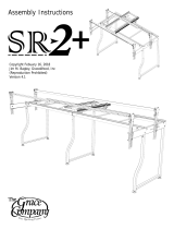
The Gracie
Home Machine Quilting System
Contents
Wood Parts: Box 1 (Queen)............................2
Hardware: Box 2 (Queen) ..............................3
Wood Parts: Box 1 (King) ...............................5
Hardware: Box 2 (King) .................................6
Step 1: Leveling Foot .....................................9
Step 2: Frame Ends .......................................9
Step 3: Middle Legs .....................................10
Step 4: Table-Track Support .........................12
Step 5: Table-Wood Surface
.........................13
Step 6: Table-Plastic Track ...........................14
Step 7: Rail Brackets
...................................14
Step 8: Rails
...............................................15
Step 9: Rail locations ...................................16
Step 10: Carriage ........................................18
Fabric Installation
........................................19
Making Cloth Leaders
..................................20
Installing Fabric Layers To The Rails .............21
Step 1: Quilt Backing ..................................21
Step 2: Quilt Top
........................................21
Step 3: Batting ...........................................21
Step 4: Attaching Layers To Take-Up Rail
.....21
The Four-Inch Principle ................................22
Bungee Clamp Assembly ..............................22
Copyright May 15, 2011
GraceWood, Inc
(Reproduction Prohibited)
Print Date 06-09-2011

Pg. 2
(4) Angled Height
Adjustable Leg
(1) Back Middle
Height Adjustable
Leg
(1) Front Height
Adjustable Leg
(1) Right
Frame End
(1) Left Frame
End
(1) Middle Leg
Top
(1) Arched
Middle
(2) Vertical
Brace
(2) Bungee Arm
(1) Right Take Up
Rail Bracket
(1) Right Fabric
Rail Bracket
(1) Left Take Up
Rail Bracket
(1) Left Fabric
Rail Bracket
(2) B Angle
Brace
(2) Bungee
Rail Holder
(2) Middle
Leg Support
(2) Frame End
Extension
(1) Left Rail
Bracket
Extension
(1) 5ft Table
(1) 3ft Table
(1) Right Rail
Bracket
Extension
(2) A Angle
Brace
Wood Parts: Box 1 (Queen)

Pg. 3
(28) M8 x 30mm
Connector Bolt
(24) M6 x 30mm
Connector Bolt
(14) M6 x 35mm
Connector Bolt
(26) M6 x 20mm
Connector Bolt
(28) M3.5 x 15mm
Self-Threading Screw
(36) M5 x 10mm
(SBHCS)
(18) M5 x 16mm
(SBHCS)
(8) M8 x 45mm
Carriage Bolt
(3) M6 x 40mm
Truss Bolt
(8) M8 Washer
(9 I.D. x 32 O.D. x 2mm)
(8) M8 Washer
(8.5 I.D. x 20 O.D. x 1.5mm)
(4) M8 Nylock Nut
(8) M8 Jam Nut
(18) M6 Square Nut
(1) 10mm/13mm Wrench
(1) 3mm Allen
Wrench
(4) Bungee Stop
(1) 5mm Allen
Wrench
(4) Bungee Clamp
(1) 4mm Allen
Wrench
(CB)
(CD)
(CE)
(CF)
(SA)
(SB)
(SC)
(BA)
(BB)
(WA)
(WB)
(NA)
(NC)
(NB)
(10) M6 Hex Nut
(ND)
(6) M4 x 30mm Pan Head
Self-Threading Screw
(BC)
(1) Fabri-Fast Tool
Hardware: Box 2 (Queen)

Pg. 4
(7) Leveling Foot
Saddle
(7) Leveling Foot
(6) End Cap
Shoulder
(4) M8 Plastic Knob
(3) Ratchet Stop
(3) Square End Cap
(3) Round End Cap
(3) Ratchet Wheel
(2) 2” Rail Coupler
(1) 1.5” Rail Coupler
(1) 1.5” Rail
5 Foot
(2) 2” Rail
5 Foot
(1) 1.5” Rail
3 Foot
(2) 2” Rail
3 Foot
(PA)
(PB)
(FA)
(FB)
(PF)
(PE)
(PD)
(PC)
(2) 3 Foot Track
Support
(2) 5 Foot Track
Support
(3) Fabrifast Tubing
(1) Speed Control
(2) 8 Foot Plastic Track
(2) 5 Foot Plastic Track
Hardware (Continued): Box 2 (Queen)

Pg. 5
Wood Parts: Box 1 (King)
(1) Back Height
Adjustable Leg
(1) Front Height
Adjustable Leg
(1)
Top
(1) Arched
Middle
(2) Back
Vertical
Brace
(2) Middle
Leg Support
(1) 3ft Table

Pg. 6
(4) M8 x 30mm
Connector Bolt
(4) M6 x 30mm
Connector Bolt
(10) M6 x 35mm
Connector Bolt
(14) M6 x 20mm
Connector Bolt
(12) M3.5 x 15mm
Self-Threading screw
(60) M5 x 10mm
(SBHCS)
(6) M5 x 16mm
(SBHCS)
(14) M6 Square Nut
(3) Leveling Foot
Saddle
(3) Leveling Foot
(2) End Cap
Shoulder
(1) Square End Cap
(1) Round End Cap
(4) 2” Rail Coupler
(1) 1.5” Rail Coupler
(1) 1.5” Rail
3 Foot
(4) 2” Rail
3 Foot
(CB)
(CD)
(CE)
(CF)
(SA)
(SB)
(SC)
(NC)
(PB)
(FA)
(FB)
(PE)
(PD)
(2) M6 Jam Nut
(ND)
(2) M4 x 30mm Pan Head
Self-Threading Screw
(BC)
(2) 11 Foot Plastic
Track
(1) 3mm Allen
Wrench
(1) 5mm Allen
Wrench
(1) 4mm Allen
Wrench
(1) 13mm Wrench
(4) Fabrifast Tubing
(2) 3 Foot Track
Support
(1) 2” Rail
5 Foot
Hardware: Box 2 (King)

Pg. 7
CARE OF YOUR GRACIE
The wooden parts on your Gracie frame system can be used nished (Stain, Varnish, etc.), or unnished.
Most people use it unnished with no problem, and doing so does not adversely affect warranty coverage.
However, for extra protection, or to give it a nished look, you may seal, stain and/or nish the frame using
a number of different applications. This is best done BEFORE YOU ASSEMBLE your frame.
To seal the wood, we recommend an application of tung oil or Danish Oil nish that will help preserve
the wood and will help to prevent warping. Some prefer to use a urethane coat to add a more glossy nish.
Test stain on an inconspicuous place. Many different nishes and/or stains may be suitable for sealing and
beautifying your frame. You may want to consult your local paint retailer for nishes that are easy to apply
and dry hard–not oily.
Use and Storage Tip
--Store frame in a dry place to avoid the possibility of moisture coming into contact with your wood.
One-Year Limited Warranty
GraceWood, Inc. will replace or repair, at our choosing, any part of the Gracie Machine Quilting System
which may be shown to be defective. This warranty does not cover parts damaged through misuse,
improper storage, improper assembly, loss, natural events and willful or accidental destruction. Defective
parts may be returned only with a valid RMA# which may be obtained by calling GraceWood, Inc. at
1-800-264-0644 or 1-801-485-6688.
NOTE: Warranty card must be lled out, stamped and mailed to the address on the card within 30 days of
purchase.
Contact Information
For Technical Support or any other correspondence concerning your Gracie frame, call 1-800-264-0644 ~
OR ~ E-mail: support@graceframe.com ~ OR ~ Fax: (801) 908-8888 ~
OR ~ Write to:
The Grace Company
P.O. Box 27823
Salt Lake City, UT 84127
For details on accessories and other information, see us online at www.graceframe.com.
For shipping of materials to The Grace Company address package (postage prepaid) to:
The Grace Company
2225 South 3200 West
Salt Lake City, UT 84119
Materials may be returned only with a valid RMA# or Returned Merchandise Authorization Number which
may be obtained by calling GraceWood, Inc. at 1-800-264-0644. If you call after business hours (M-F
8:00 a.m. – 5 p.m., MST) be assured that your call will be returned the next business day, if you leave a
message.
Please report any errors in these instructions or make comments to the following:
support@graceframe.com
Grace Quilting Frames and Hoops: Innovation and Evolution
Grace Quilting Systems have been developed over the past two decades with several original design
innovations. Additionally, because of feedback from many of the thousands of quilters who have purchased
and use our machine quilting systems, we have been able to make a frame that will truly enhance the
entire process of machine quilting from beginning to end. If you have any suggestions that will help us to
improve our product or service, let us know using one of the above contact methods.

Pg. 8
WELCOME!
As you begin assembly of your new Gracie home machine quilting system, keep in the mind the
following:
1) Plan to spend a minimum of 2-4 hours in assembly. This process will be simple and step-by-step.
2) Read through each step completely before beginning that step.
3) Using the parts list as a reference, take the parts out of the box and make sure that you have
them all. (If there is something missing or broken, contact the Grace Company at 1-800-264-0644.
Our ofces are open from 8:00 am - 5:00 pm MST Mon.-Fri. If calling after hours, you may leave your
message and we will promptly ship any item needed).
4) For your convenience, an “L” and “R” have been etched into the INSIDES of many pieces to help
you distinguish between left and right parts and inside and outside of parts.
5) Identify Hardware Packets: All hardware is separated by type. Each packet is labeled for ease in
identication.
6) This is a new product! We welcome your feedback on this product or these instructions. If you
encounter a problem during assembly or use of the Gracie, and you can’t seem to overcome it, call us
before frustration sets in!
Tools Needed:
10mm Socket Wrench (provided)
Phillips Screw Driver (Cordless Preferred)
3mm, 4mm, and 5mm Allen wrenches (provided)
Fabri-Fast Tool (to be used when installing your fabric)

Pg. 9
(8) M8 x 45mm
Carriage Bolt
(8) M8 Washer
(9 I.D. x 32 O.D. x 2mm)
(8) M8 Washer
(8.5 I.D. x 20 O.D. x 1.5mm)
(4) M8 Nylock Nut
(8) M8 Jam Nut
(4) M8 Plastic Knob
(24) M8 x 30mm
Connector Bolt
(8) M6 x 30mm
Connector Bolt
(BA)
(CB)
(CD)
(WB)
(WA)
(NB)
(NA)
(PA)
(4) M6 Square Nut
(NC)
Hardware required:
Wood parts required:
1) Right Frame End
1) Right Take-up Rail Bracket
1) Right Fabric Rail Bracket
1) Left Frame End
1) Left Take-Up Rail Bracket
1) Left Fabric Rail Bracket
2) Bungee Arm
2) Bungee Rail Holder
1) Right Frame End Extension
1) Left Frame End Extension
2) Rail Bracket Extension
4) Angled Height Adjustable Leg
2) A Angle Brace
2) B Angle Brace
Step 1: Leveling Foot
Step 2.1: Secure Angled Height Adjustable Legs
to the lower backside of each frame end using (CB)
M8 x 30mm Connector Bolts as shown in Fig. 2.1
Step 2.2: Secure a Frame End Extension to each
frame end using (CB) M8 x 30mm Connector
Bolts as shown in Fig. 2.2
Perform the outlined steps on the Left and Right Frame Ends
to complete the Frame End assemblies.
Step 1.1: Thread each of the (FA) Leveling Feet into the (FB) Leveling
Foot Saddles.
Step 1.2: Attach saddle feet to each of the legs, as shown using the (SA)
M3.5 x 15mm Self-Threading Screws.
Attach a Leveling Foot to each of the legs included with your frame.
Note 1: The Front Height Adjustable Leg requires 2 Leveling Feet.
Fig. 1.1
K
56 or
Q
28 or
C
16 M3.5 x 15mm
Self-Threading Screw
(SA)
K
14 or
Q
7 or
C
4
Leveling Foot Saddle
(FB)
K
14 or
Q
7 or
C
4
Leveling Foot
(FA)
Step 2: Frame Ends
(CB)
(CB)
Fig. 2.1
Fig. 2.2
Hardware required:
Wood Parts required:
4 Angled Height Adjustable Leg
K
2 or
Q
1 Back Middle Height
Adjustable Leg
K
2 or
Q
1 Front Height Adjustable Leg
(FB)
(FA)
(SA)
K
King assembly
Q
Queen assembly
C
Crib assembly

Pg. 10
Step 2.3: Attach the A and B Angle Braces to the back
side of the Frame Ends by using (NC) M6 Square Nuts and
(CD) M6 x 35mm Connector Bolts.
Note 2.3.1: The “T” Slots in the braces should always
face in.
Note 2.3.2: You may need to re-adjust the Angled Height
Adjustable Legs to get the braces positioned correctly.
(CD)
Fig. 2.3
(BA)
(WB)
(NB)
Fig. 2.5
Step 2.5.1: Insert (BA) M8 x 45mm Carriage
Bolts through the 4 holes indicated (in Fig. 2.4), in
each Frame End.
Step 2.5.2: Place a (WB) M8 Washer (8.5 ID
x 20 OD x 1.5mm), followed by a (NB) M8 Jam
Nut onto the exposed end of each Carriage Bolt.
Tighten the Jam Nuts until the bolts square
shoulders are pulled completely into the wood.
Step 3.1: Secure the Middle Leg Top to the
Arched Middle using (CD) M6 x 35mm Connector
Bolts, and (NC) M6 Square Nuts .
(NC)
(CD)
Fig. 3.1
K
8 or
Q
4 M8 x 30mm
Connector Bolt
(CB)
K
8 or
Q
4 M6 x 30mm
Connector Bolt
K
20 or
Q
10 M6 x 35mm
Connector Bolt
(CD)
(CE)
K
20 or
Q
10 M6 Square Nut
(NC)
Wood Parts:
K
2 or
Q
1 Middle Leg Top
K
2 or
Q
1 Arched Middle
K
4 or
Q
2 Vertical Braces
K
4 or
Q
2 Middle Leg Supports
Step 3: Middle Legs
Materials required:
Note: If you are assembling the King size
frame complete this step 2 times.
Carriage Bolt
Locations
(NC)
Note: Skip this step when setting up in
crib size.
Hardware required:
K
King assembly
Q
Queen assembly
Step 2.4.1: Secure a Rail Bracket Extension to
each Frame End Extension using (CB) M8 x 30mm
Connector Bolts as shown in Fig. 2.4
Note 2.4: An “L” and “R” have been engraved
onto the Rail Bracket Extensions, to indicate which
frame end they are to be attached.
(CB)

Pg. 11
(CD)
(NC)
(NC)
Step 3.3: Insert (NC) M6 Square Nuts into the “T” slots located in the Vertical Braces (2 ea.), as well
as those located in the Middle Leg Supports (2 ea.).
Step 3.4: Secure the Middle Leg Supports to the Vertical Braces using (CD) M6 x 35mm Connector
Bolts.
Step 3.5: Secure the Middle Leg Supports to the Middle Leg Top using (CD) M6 x 35mm Connector
Bolts.
Fig. 3.3
Fig. 3.4
Fig. 3.6
Inside
(CB)
Step 3.6: Finally, attach the Front and Back Middle Legs
to the lower holes in the Vertical Braces using (CB) M8 x
30mm Connector Bolts.
Note 3.6: Attach the adjustable legs to the inside of the
Vertical Braces. This should be the side of the Vertical Brace
opposite of the side with the threaded inserts.
Threaded
inserts
Note 3.King: If you are building the King size version of
the frame, you will need to build an additional pair of middle
legs. These parts are located in the King boxes.
Fig. 3.2
“T” Slots
face out
Threaded
inserts
(CE)
Step 3.2: Attach the Vertical Braces to the
Arched Middle using (CE) M6 x 30mm Connector
Bolts.
Note 3.2.1: Make sure that the threaded inserts
are on the back side of the Arched Middle, in
relation to the Vertical Brace you are attaching.
Note 3.2.2: Make sure that the “T” slots on the
vertical braces face out.

Pg. 12
3 ft
5 ft
3 ft
5 ft
Step 4: Table-Track Support
Materials required:
Step 4.1.1: Attach the 3 foot
Aluminum Track Supports to the Left
Frame End Assembly as shown (for Crib
use the 5 Foot Aluminum Track Support).
Step 4.1.2: Use (CE) M6 x 30mm Connector
Bolts to fasten the Track Support to the frame
end.
Step 4.1.3: Use (CF) M6 x 20mm Connector
Bolts to fasten the Track Supports to the Angle
Braces.
(CE)
Aluminum Track
Supports
K
16 or
Q
8 or
C
4 M6 x 30mm
Connector Bolt
K
24 or
Q
12 or
C
4 M6 x 20mm
Connector Bolt
(CE)
(CF)
K
4 or
Q
2 3ft. Aluminum Track Support
2 5ft. Aluminum Track Support
1 Left Frame End Assembly
1 Right Frame End Assembly
K
2 or
Q
1 Middle Leg Assembly
Step 4.2: Attach the 5 foot Aluminum Track Supports to
the Right Frame End Assembly as done in step 4.1 (For the
King setup use 3 Foot Aluminum Track Supports for
this step.)
Step 4.3.1: Secure the Middle Legs to the ends of
the previously attached Aluminum Track Supports, for
both the Left, and Right Frame Ends.
Step 4.3.2: Use (CF) M6 x 20mm Connector Bolts to
fasten the Track Supports to the Middle Legs.
Note: Align the edges of the Aluminum Track
Supports before completely tightening the bolts into
the Middle Legs.
Fig. 4.1
Fig. 4.3.1
Fig. 4.3.2
(CF)
Queen
King
Note: For Crib only do steps 4.1.1 through step 4.2
Crib
5 ft
(CF)
K
King assembly
Q
Queen assembly
C
Crib assembly

Pg. 13
Step 5: Table-Wood Surface
Hardware required:
K
20 or
Q
14 or
C
8 M6 x 20mm
Connector Bolt
(CF)
K
20 or
Q
14 or
C
8
M6 Hex Jam Nut
(ND)
Note: For Crib Assembly only do steps 5.2 through step 5.4
Step 5.1: Place the 3 Foot Table Surface onto the frame over the
3 Foot Track Supports.
Note 5.1: There are holes in only one end of the 3 Foot Table.
Make sure that these holes are placed over the middle legs. (This
rule applies to the King setup also.)
Step 5.2: Place the 5 Foot Table onto the frame over the
5 foot track supports.
Step 5.3.1: Secure the Table surfaces to the
frame by rst inserting the (CF) M6 x 20mm
Connector Bolt through each of the
available locations.
Note 5.3.2: There are
some holes in the tables
that will not be used, they
are provided for alternate
frame congurations.
Note 5.3.3: If the holes in the table don’t line up with the holes in the Aluminum Track Supports the
frame may be slightly out of square. This can be corrected by pushing/pulling the front of the frame
one direction, while pushing/pulling the back of the frame the opposite direction, until the holes in
the table line up.
Step 5.4: Place (ND) M6 Hex Nuts onto the end of the bolts which pass through the Aluminum Track
Supports. Hold the Hex Nuts in place using the provided Wrench while tightening the bolts completely
using the 4mm Allen Wrench.
(CF)
Wood Parts required:
K
2 or
Q
1 3ft Table
1 5ft Table
K
King assembly only
Q
Queen assembly only
C
Crib assembly only

Pg. 14
Fig. 7.1
Step 7: Place the Rail Brackets onto the frame ends
as shown.
Step 7.1: Secure the Rail Brackets to each end
of the frame by rst placing a (WA) M8 Washer (9
ID x 32 OD x 2mm) onto the exposed ends of the
Carriage Bolts. Next, fasten a (PA) Plastic knob onto
the bolts in the Take-Up Rail Brackets. Put a (NA) M8
Nylock Nut onto the bolts in the Fabric Rail Brackets.
Note 7.1.1: You will adjust the Fabric Rail Brackets
permanent location later on.
The Take-Up Rail Brackets need to be adjusted
frequently while quilting to accommodate for the
increasing diameter, as the nished quilt sections are
rolled onto the Take-Up Rail.
(PA)
(NA)
Step 6.1: Insert the Plastic Track by rmly
pressing one end of the track into the Aluminum
Track Support. Work your way down the track
until each piece has been completely pressed
into the track supports.
DETAIL A
Fully inserted track
Step 6: Table-Plastic Track
Step 7: Rail Brackets
Hardware required:
(8) M6 x 30mm
Connector Bolt
(8) M8 Washer
(9 I.D. x 32 O.D. x 2mm)
(4) M8 Nylock Nut
(4) M8 Plastic Knob
(CE)
(WA)
(NA)
(PA)
King
(2) 11ft Plastic track
Queen
(2) 8ft Plastic track
Materials required
(WA)
Take-Up Rail
Bracket
Fabric Rail
Bracket
Crib
(2) 5ft Plastic track
Wood Parts Required
1) Right Take-Up Rail Bracket
1) Left Take-Up Rail Bracket
1) Right Fabric Rail Bracket
1) Left Fabric Rail Bracket

Pg. 15
Fig. 7.3
(CE)
(CE)
Fig. 7.2
Step 8: Rails
K
96 or
Q
36 M5 x 10mm (SBHCS)
(not in crib)
K
24 or
Q
18 M5 x 15mm (SBHCS)
3 Ratchet Stop
K
4 or
Q
3 Square End Cap
K
4 or
Q
3 Round End Cap
3 Ratchet Wheel
(SB)
(SC)
(PB)
(PF)
(PE)
(PD)
(PC)
K
8 or
Q
6 End Cap Shoulder
3 M6 x 40mm Truss Bolt
(BB)
K
8 or
Q
6 M4 x 30mm Pan Head
Self-Threading Screw
(BC)
Hardware
Step 7.2: Attach a Bungee Rail Holder to each of the
Bungee Arms using (CE) M6 x 30mm Connector Bolts.
Note 7.2: Make sure to have the threaded insert (in
the rail holder) facing away from the Bungee Arm. Also,
make left and right pairs of the Bungee Arms, as shown
in Fig 7.2
Step 7.3: Bolt the Bungee Arms to each of the Fabric
Rail Brackets using (CE) M6 x 30mm Connector Bolts, as
shown in Fig. 7.3
Rails
(
K
2 or
Q
1) 1.5” Rail Coupler (not in Crib)
(
K
2 or
Q
1) 1.5” x 3 ft. Aluminum Rail
(1) 1.5” x 5 ft. Aluminum Rail
(
K
6 or
Q
2) 2” Rail Coupler (not in Crib)
(
K
6 or
Q
2) 2” x 3 ft. Aluminum Rail
(
K
3 or
Q
2) 2” x 5 ft. Aluminum Rail
Crib rail = (1) 5 ft = 5 ft (only end caps required, details at Step 8.5)
Queen rail = (1) 3 ft + (1) 5 ft = 8 ft
King rail = (1) 3 ft + (1) 5 ft + (1) 3 ft = 11 ft
K
King assembly
K
Queen assembly

Pg. 16
(SB)
Step 8.1: Build the Take-Up Rail (1.5” Diameter, smaller) by rst
inserting a 1.5” Rail Coupler halfway into one end of the 1.5” x 5
Foot Rail. (For King size: attach a Rail coupler into both ends of
the 5 foot rail section.)
Note 8.1: Center the holes in the Coupler with the slotted holes in
the rails.
Step 8.2: Fasten the Coupler to the Rail using (SB) M5 x 10mm
(SBHCS).
Note 8.2: To ensure proper hole alignment, partially thread each
of the 6 required screws into each half of the Coupler before
completely tightening.
Step 8.3: Place a 1.5” x 3 Foot Rail onto the exposed end of each
of the Rail Couplers, and secure into place as done in step 8-2.
Note 8.3: Remember to partially thread each of the 6 screws in
before completely tightening any of them.
Step 8.4: Repeat steps 8.1 to 8.3 using the remaining rails, and
couplers (2” Diameter, larger) to build 2 more rails for queen, 3 rails
if building King.
Step 8.5: Completely press the Round End Caps onto
the end of each of your 5 foot rail sections. (With
King size, you may put the end cap onto ether rail
end.)
Step 8.6: Completely press the Square End Caps
onto the opposite end of the rails.
Note 8.6: The end caps work on both the 1.5”, and
the 2” rails.
Step 8.7: Secure the end caps to the rails using (SC)
M5 x 16mm (SBHCS)
(SC)
(SC)
Step 9: Rail locations
Fig. 9.1
Fig. 8.1
Fig. 8.5
Fig. 8.6
Take-Up Rail 1.5”
Quilt Back Rail 2”
Quilt Top Rail 2”

Pg. 17
Step 9.1: (Quilt Back - 2 inch Rail) Place a Ratchet Wheel onto the Square End Cap located on the
end of one of the 2” rails. Make sure to have the ratchet wheel arranged as shown in Fig. 9.1 (Quilt
Back). This rail will ratchet clockwise when adjusting fabric tension.
Step 9.2: Insert the Square End Cap into the top hole in the Right Fabric Rail Bracket.
Step 9.3: To get the Rail into the Left Fabric Rail Bracket, pull the Rail Bracket away from the Rail.
When there is a large enough opening slide the Round End Cap into the top hole in the Left Rail
Bracket.
Step 9.4: (Quilt Top - 2 inch Rail) Place a Ratchet Wheel onto the Square End Cap on a 2” Rail.
Make sure to have the Ratchet Wheel arranged as shown in Fig. 9.1 (Quilt top). This Rail will ratchet
counter-clockwise.
Step 9.5: Insert the end of the Rail with the Square End Cap into the slot in the Right Fabric Rail
Bracket. Simultaneously insert the end of the rail with the Round End Cap into the slot in the Left
Fabric Rail Bracket.
Fig. 9.2
Queen
King
Take-Up Rail
Take-Up Rail
Quilt Back Rail
Quilt Top Rail
Quilt Back Rail
Quilt Top Rail
Batting Rail

Pg. 18
Step 9.6: (Batting rail - 2 inch Rail) (Optional, provided with King only) Insert the Square End
Cap into the slot in the Right Frame End Extension. Insert the Round End Cap into the slot in the
Left Frame End Extension.
Complete the remaining portion of this step after building the carriage (Step 10).
Step 9.7: (Take-Up Rail) Place the remaining Ratchet Wheel onto the Square End Cap on the 1.5”
Rail. Make sure to have the Ratchet Wheel arranged as shown in Fig. 9.1 (Take-Up Rail). This Rail
will ratchet clockwise.
Step 9.8: After passing one end of the rail through the throat of your sewing machine, insert the end
of the rail with the Square End Cap into the slot in the Right Take-Up Rail Bracket. Simultaneously
insert the end of the Tail with the Round End Cap into the slot in the Left Take-Up Rail Bracket.
Step 9.9: Attach a Shoulder End Cap onto each end of each Rail using (BC) M4 x 30mm Self-
threading Screws. Figs. 9.9.1, & 9.9.2
Note 9.9: Be careful to not ever tighten the screws that hold on the Shoulder End Caps. As you
tighten the screws, watch the gap indicated in Fig. 9.9.3. The gap is required to allow the rails to roll
freely.
Step 9.10: Attach Ratchet Stops to the Right End Rail Brackets using (BB) M6 x 40mm Truss Bolts,
as shown in g. 9.10, also use Fig. 9.1 as a reference. (Finger tighten only)
Fig. 9.9.1
Fig. 9.9.2
Step 10: Carriage
Please refer to the instruction booklet included with the carriage. The carriage manual will guide you
through the process of building your carriage and placing it on your quilting frame, as well as sewing
machine placement.
Fig. 9.10
Finger tighten only
Gap Required
Fig. 9.9.3
(BC)

Pg. 19
Congratulations! You have completed the assembly of your Gracie Quilting Frame.
Save any extra hardware you have left over (if you assembled the crib size you will have bolts and
wood pieces remaining).
Store these in a safe, dry place for later use.
All that remains is to install your fabric and begin quilting!
With the specially designed Fabri-Fast rails, installing your fabric is easier on the Gracie Frame than
on any other frame. Each rail has a Fabri-Fast slot and accompanying tubing. These work together
to make your fabric installation much easier and faster than using tape, tacks or Velcro®.
Before you begin, please locate the plastic Fabri-Fast tool included in your shipment.
We recommend you begin with practice material allowing you to experiment with machine settings
and stroke techniques.
NOTE: As you cut your fabric layers, we recommend making the quilt backing about 6-8” longer and
2-4” wider than your top. This will allow for a little give in the backing, especially if using thicker
batting.
Fabric Installation
Methods of Installation
● The recommended method for installing fabric onto the rails is to make and use Cloth
Leaders (instructions to follow). This will enable you to nish your quilt completely, to
the end, without having to take your quilt off the rails.
● It is very important to cut all your fabric square. This will make the following steps much
easier! A rotary cutter helps achieve more precise results.
The following is a brief overview to show which fabric layer goes on each rail.
OVERVIEW:
Step 1: Load Batting to the batting rail and roll up.
Step 2: Load Quilt Top to the quilt top rail and roll up.
Step 3: Load Quilt Backing to quilt back rail and roll up.
Step 4: Attach Quilt Backing to Take-Up rail.
Step 5: Attach Batting to Take-Up rail.
Step 6: Attach Quilt Top to Take-Up rail.
Top
Back
Take-Up
Batting

Pg. 20
Making Cloth Leaders
●First, select your cloth leader material. We recommend using a good quality muslin or similar fabric
that has a good thread count. Be aware, however, that if the fabric is too thick, it may prove more
difcult getting it installed into the rail slot.
●Surge or hem your cloth leaders on all sides.
●Make cloth leaders so that their lengths are as follows.
● Mark a dashed line along the
length of your leader about ½” in
from the edge. You will use this
as a guide to help you insert your
leader into the slot in a straight
line. (OPTIONAL: For a straighter
cloth leader installation, some may
consider it easier to make a casing
and push the tubing into the casing
before installing it into the slot. If
you wish to do this, create a casing on one end of each leader by folding over the fabric one inch
(1”), and, using your presser foot as a guide, stitching the fabric together 3/4” from the fold. This
will leave about ¼” of fabric beyond the
stitching. Leave the edges open on both
ends. You may then slide your tubing into
the casing).
● Mark each cloth leader at the center (length-wise).
● Mark (or baste) a straight line about ½” in from the opposite (non-casing, or non-dashed) end of
the leader. This will be the line to which you attach your fabric layer.
● Center your cloth leader lengthwise along the rail. Using Grace’s Fabri-Fast
TM
System, take a piece
of plastic tubing (cut to the appropriate
length) holding your cloth leader to the slot
(lining up the dashed line), and press the
tubing over the leader and into the slot.
Use the Fabri-Fast tool to press the rest of
the tube and fabric in quickly and easily. If
you have made a casing, line up the casing
with tubing over the slot and press it into
the slot using the Fabri-Fast tool.
● This illustration shows the cloth leaders
installed on each rail prior to your quilt
layers being installed.
18"
24"
5"
Take-Up Leader
Top Leader
Backing Leader
3/4" Casing
3/4" Casing
3/4" Casing
Fabrifast Tubing
Cloth Leader
Take-Up Leader
5”
Quilt Top Leader
24”
Quilt Back Leader
18”
/