Page is loading ...

IMPORTANT NOTE:
“Left” Sticker Denotes the
Left Side Bracket Extension
LEFT Bracket
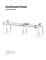
Step 2: Assembly of Take Up Rail Bracket
Extensions
Parts needed:
(2) - Take Up Rail Bracket Extensions
(4) - M6 x 16 mm SBHCS (4)
(4) - M6 Hex Nuts
Note: Be sure to install the Left Side Bracket Ex-
tension to the left side of the frame as shown.
Note: (4) M6 x 16mm SBHCS and (4) M6 Hex Nuts
from step 1-2.
2-1: Insert the plastic wheel bearing removed from
step 1-4 into the existing take up rail bracket (Fig.
2-1).
2-2: Fasten (4) M6 x 16mm SBHCS with the 4mm
Allen wrench and (4) M6 hex nuts with a 10mm
open wrench end from the take up rail bracket (Fig.
2-2).
2-3: Repeat steps 2-1 and 2-2 or the opposite end
of the frame.
Fig. 2-1 Fig. 2-2
L
E
F
T

Page 1
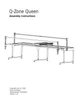
Idler Rail Accessory
Parts List
Parts List .................................................................................................................................. 2
Hardware ................................................................................................................................. 2
Assembly Steps
Step 1: Disassembly of Take Up Rail Brackets .............................................................................. 3
Step 2: Assembly of Take Up Rail Bracket Extensions ................................................................... 4
Step 3: Assembly of Idler Rail .................................................................................................... 4
Step 4: Assembly of Take Up Rail .............................................................................................. 5
Step 5: Attachment of Take Up Rail Assembly ................................................................................. 5

Page 2
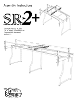
Parts List
Hardware
Rail (2)
Rail Coupler (2) 2 ft Rail (1)
Take Up Rail Bracket
Extension (2)
Ratchet Wheel (2)
6mm Allen Wrench (1)
4mm Allen Wrench (1)
3mm Allen Wrench (1)
13mm and 10mm Open
End Wrench (1)
M6 Hex Nut (4)M6 x 16 mm
SBHCS (4)
M5 x 16mm
SBHCS (6)
FabriFast Tubing (1)

Plastic Wheel
Bearing
Page 3
Step 1: Disassembly of Take Up Rail Brackets
and Rail
1-1: Uncouple the rail ends from take up rail brack-
ets (Fig.1-1).
1-2: Unfasten the M6 x 16mm SBHCS with 4mm
Allen wrench and M6 hex nuts with a 10mm open
wrench end from the take up rail bracket (Fig.1-1).
1-3: Remove the M10 x 35mm Connector bolt from
the rail ends with a 6mm Allen Wrench and remove
the plastic wheel bearing (Fig. 1-2).
1-4: Repeat steps 1-3 for the opposite end of the
frame.
Fig. 1-1
Fig. 1-2
Step 2: Assembly of Take Up Rail Bracket
Extensions
Parts needed:
(2) - Take Up Rail Bracket Extensions
(4) - M6 x 16 mm SBHCS (4)
(4) - M6 Hex Nuts
Note: (4) M6 x 16mm SBHCS and (4) M6 Hex Nuts
from step 1-2.
2-1: Insert the plastic wheel bearing removed from
step 1-4 into the existing take up rail bracket (Fig.
2-1).
2-2: Fasten (4) M6 x 16mm SBHCS with the 4mm
Allen wrench and (4) M6 hex nuts with a 10mm
open wrench end from the take up rail bracket (Fig.
2-2).
2-3: Repeat steps 2-1 and 2-2 or the opposite end
of the frame.
Fig. 2-1 Fig. 2-2

Rotating Latch
Page 4
Step 3: Assembly of Idler Rail
Parts needed:
Note: Disassembled rail and (2)
M10 x 35mm Connector bolts
from step 1-3.
3-1: Insert rail ends into plastic
wheel bearing for both ends of
the frame (Fig. 3-1).
3-2: Fasten the (2) M10 x 35mm
Connector bolts into the rail ends
with a 6mm Allen Wrench (Fig.
3-1).
Fig. 3-1 Fig. 3-2
Note: The rail assembly in Fig. 3-1 and 3-2 has been converted from a take up rail to a idler rail. To
have a free rolling idler rail, simply pull the rotating latch out and rotate quarter turn to disengage
(Fig. 3-2).
Ratchet Wheel
M5 x 16mm SBHCS
Step 4: Assembly of Take Up Rail
Parts needed:
2 - Rails
2 - Rail Couplers
1 - 2 ft Rail Extension
6 - M5 x 16mm SBHCS
2 - Ratchet Wheels
Note: The (8) M6 x 20mm Set Screw are pre-in-
stalled in the (2) rail couplers.
If installing for 5 ft rail assembly skip to step 4-3.
4-1: Slide a rail coupler within the inside of the
rail tube end and fasten (2) M6 x 20mm set screws
(Fig. 4-1) for 10 ft rail. Repeat process for 2 ft
extension if assembling the 12 ft rail.
4-2: Take the second rail and slide it over the rail
assembly from step 4-1 and fasten (2) M6 x 20mm
set screws (Fig. 4-1) to create a 10 ft assembly.
Add additional the 2 ft rail assembly from step 4-1
and fasten, if assembling the 12 ft rail.
4-3: Attach and fasten a ratchet wheel assembly
to the ends of the take up rail with (3) M5 x 16mm
SBHCS with a 3mm Allen wrench (Fig. 4-2).
Fig. 4-1
M6 x 20mm Set
Screw
Coupler
Fig. 4-2

Page 5
Step 5: Attachment of Take Up Rail Assembly
Parts needed:
Note: Pre-assembled rail from Step 4.
5-1: Couple the Pre-assembed take up rail assembly wheel ends into
the take up rail bracket extensions (Fig 5-1).
Congratulations assembly is now complete!
Fig. 5-1
/