Rockwell Automation Allen-Bradley 2090-KTFB-MA-AE Installation Instructions Manual
- Type
- Installation Instructions Manual

Installation Instructions
Original Instructions
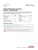
Build Your Own Kinetix TLP Motor Cables
Catalog Numbers
2090-KTPC-MA-AA, 2090-KTPC-MA-AE, 2090-KTFB-MA-AA, 2090-KTFB-MA-AE, 2090-KTBK-MB-AA, 2090-KTBK-MB-AE, 2090-KTFB-MF-AA,
2090-KTFB-MF-AE, 2090-KTPC-MC-AA, 2090-KTPC-MC-AE, 2090-KTPC-MD-AA, 2090-KTPC-MD-AE, 2090-KTPC-ME-AA, 2090-KTPC-ME-AE
For reference, see Kinetix Motion Accessories Specifications Technical Data, publication KNX-TD004, for Kinetix TLP motor and cable combinations and Kinetix TLP motor
power and feedback cable specifications.
Summary of Changes
This manual contains new and updated information as indicated in the following table.
Before You Begin
Remove all packing material from within and around the item. After unpacking, verify the catalog number against the purchase order, and visually inspect each connector
for damage. If necessary, notify the carrier of any shipping damage immediately.
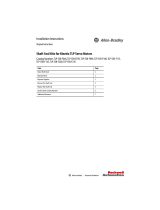
Topic Page
Before You Begin 1
Wiring Connectors 2
Rectangular Connectors 3
Military-style Connectors 8
Catalog Number Descriptions 12
Additional Resources 12
Topic Page
Updated figures with enhancements to help you understand how the kits are assembled. Throughout
Added Military-style Power/Brake Connector (extension) Cable Examples. 9
Added Ring Lug Specifications. 9
Added Catalog Number Descriptions. 12
ATTENTION: Arcing or unexpected motion can occur if the power, brake, or feedback cables are connected or disconnected while power is applied.
Always remove power to the servo drive before connecting or disconnecting cables at the drive or at the motor.
ATTENTION: To avoid the hazard of electrical shock, make sure that shielded power cables are grounded at a minimum of one point. To help prevent
the build-up of electrical energy, factory-supplied power cables use one of these grounding techniques:
• The overall shield is bonded to the connector housing.
• A section of the overall shield is exposed for connection to ground.
• The overall shield is connected to a ground wire.
If the exposed cable braid or a ground wire is present, connect it to the power cable clamp, housing, or another suitable chassis ground on the drive.
ATTENTION: Do not tightly gather or coil the excess length of a power cable. Heat is generated within a cable whenever power is applied. Always
position a power cable so it can freely dissipate any heat. A power cable must not be coiled, except for temporary use when building or testing a
machine. If you temporarily coil a power cable, you must also derate the cable to meet local code or follow an authoritative directive, such as
Engineering Section 310.15(C) of the NEC Handbook.
IMPORTANT
The following factors must be considered when selecting bulk cable.
• Power cables must be rated to voltage higher than the system voltages at all operating conditions.
• Cable conductor current carrying capacity (after all applicable deratings) must be ≥ the connected motor continuous rated current.
• Cables must meet all local and global regulatory requirements.
• Cable must have overall shield to meet the applicable electromagnetic radiation/emission requirements.

2 Rockwell Automation Publication 2090-IN048B-EN-P - April 2020
Build Your Own Kinetix TLP Motor Cables Installation Instructions
Storage
To help prevent damage to parts you aren’t ready for yet, use them on a first in/first out basis and leave them in the original packaging to avoid storage contamination.
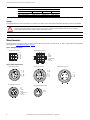
Wiring Connectors
Rectangular connectors are used on TLP-x046…TLP-x100 servo motors. Military-style connectors are used on TLP-x115…TLP-x235. For all the connector kit catalog numbers
and descriptions, see Catalog Number Descriptions on page 12.
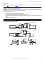
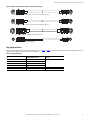
Figure 1 - Rectangular Connectors
Figure 2 - Military-style Connectors
IMPORTANT
For optimal performance of the system, the power cable capacitance must not exceed.
ATTENTION: Prolonged exposure to ultraviolet light can deteriorate the chemical composition that is used in the product material. Do not store
product near any of these chemicals as they can cause stress, corrosion, or cracking in the material: Alkalies, Ammonia, Citrates, Phosphates
Citrates, Sulfur Compounds, Amines, Carbonates, Nitrites, Sulfur Nitrites, Tartrates.
IMPORTANT
Storage temperature for these components is -20…+70 °C (-4…+158 °F).
Conductor to Conductor Capacitance:
12 AWG or smaller: 120 pF/m 08 AWG: 150 pF/m 06 AWG: 160 pF/m 04 AWG: 190 pF/m
Conductor to Shield Capacitance:
12 AWG or smaller: 220 pF/m 08 AWG: 270 pF/m 06 AWG: 290 pF/m 04 AWG: 320 pF/m
1 - U
2 - V
3 - BR+
4 - W
5 - PE
6 - BR-
MA-type Power Connector
1 - T+
4 - T-
2 - BAT +
5 - BAT-
9 - Shield/Drain
8 - GND
7 - DC +5V
MA-type Feedback Connector
31
97
2
1
3
4
5
6
A - BR-
B - BR+
MB-type Holding Brake Connector
B - W
E - PE
F - U
G - BR+
H - BR-
I - V
MC- type P owe r Con n e c tor
A - BR+
B - BR-
D - U
E - V
F - W
G - PE
MD-type Power Connector
A - U
B - V
C - W
D - PE
ME-type Power Connector
A - T+
B - T-
C - BAT +
D - BAT-
L - Shield/Drain
R - GND
S - DC +5V
MF-type Feedback Connector

Rockwell Automation Publication 2090-IN048B-EN-P - April 2020 3
Build Your Own Kinetix TLP Motor Cables Installation Instructions
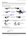
Rectangular Connectors
Rectangular connector kits are available in 6-pin and 9-pin configurations. There are two 6-pin kits for power/brake, the 2090-KTPC-MA-AA kit for standard cables and the
2090-KTPC-MA-AE kit for extension cables. There are two 9-pin kits for feedback, the 2090-KTFB-MA-AA kit for cables and the 2090-KTFB-MA-AE kit for extension cables.
The connector kits include receptacle and pins. The extension kits also include plug and sockets. The 9-pin kits also include plug and receptacle clamps with assembly
hardware.
With flying-lead power and feedback conductors prepared at one end of the cable, you assemble the receptacle with crimped sockets and clamp for mating with the
on-motor cable. Extension cables can also be assembled.
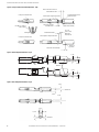
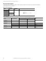
Figure 3 - Rectangular Power/Brake Connector Cable Examples
(1) Strip lengths vary slightly, depending on drive requirements. Refer to Additional Resources on page 12 for the drive user manual with specific values.
Figure 4 - Rectangular Feedback Connector Cable Examples
Wire Selection and Preparation - 6-pin
Standard contacts accept wire size ranges of 22…18 AWG (600…1900 CMA). TPA-compatible contacts accept wire size ranges between 22…18 AWG. Terminate contacts to
stranded copper lead wire. The insulation diameter range, strip length, and crimp height are determined by the wire size and are shown below.
IMPORTANT
Use caution not to nick, cut, or otherwise damage strands as you remove insulation.
10.0
(0.39)
80.0
(3.15)
450
(17.7)
25.0
(0.98)
80.0
(3.15)
100
(3.9)
8.0
(0.31)
Male Plug
Female Receptacle
Contact (pin)
Contact (socket)
Contact (pin)
2090-KTPC-MA-AE kit for
rectangular extension (bulk)
power/brake cable.
2090-KTPC-MA-AA kit for
rectangular standard (bulk)
power/brake cable to flying leads.
Flying-lead
power/brake cable
terminates at the drive.
To On-motor
Power/Brake
Connector
To On-motor
Power/Brake Connector
or Extension Cable
Connects to 2090-CTPx-MADF-xxxxx or
Customer-supplied Power/Brake Cable
Female Receptacle
See Ring Lug Specifications
on page 9.
(1)
(1)
Male Plug
Female Receptacle
Receptacle clamp is included
with 2090-KTFB-MA-AA/AE kits
(two pieces per clamp).
Plug Clamp
Contact (pin)
Contact (socket)
Contact (pin)
2090-KTFB-MA-AE kit for rectangular
extension feedback (bulk) cable.
2090-KTFB-MA-AA kit for rectangular
standard feedback (bulk) cable to flying leads.
Flying-lead feedback cable
terminates in the connector kit
appropriate for your servo drive.
To On-motor
Feedback Connector
To On-motor
Feedback Connector
or Extension Cable
Connects to 2090-CTFB-MADD-CFxxx or
Customer-supplied Motor Feedback Cable
Female Receptacle
Receptacle clamp and plug clamp are
included with 2090-KTFB-MA-AE kits
(two pieces per clamp).
Receptacle Clamp
Receptacle Clamp
Wire Conductor
Insulation
Insulation Diameter
Strip Length

4 Rockwell Automation Publication 2090-IN048B-EN-P - April 2020
Build Your Own Kinetix TLP Motor Cables Installation Instructions
For optimum crimp performance, the crimp must meet the crimp requirements and be within the area shown in Figure 5 on page 5. The crimp applied to the wire barrel
portion of the contact is the most compressed area and is critical to provide the optimum electrical and mechanical performance of the terminated contact. Effective
crimp length is defined as that portion of the wire barrel, excluding the bellmouth, fully formed by the crimping tool.
Wire Selection and Preparation - 9-pin
The contacts accept stranded wire sizes 26…22 AWG within the insulation diameter range listed below. Strip length for one-wire crimping is 3.20…3.71 mm (0.126…0.146 in.)
and 3.50…3.99 mm (0.138…0.157 in.) for two-wire crimping.
The carrier cutoff tab length must not exceed the dimension shown in Figure 6. The insulation barrel must be formed around, but not cut into, the wire insulation. Do not
crimp the contact stop. Any deformation to the contact stop compromises the insertion depth of the contact in the contact cavity of the housing. The front bellmouth must
be visible. The end of the wire must be flush with the end of the wire barrel or protrude no more than the dimension shown in Figure 6
. Do not move or bend the locking
lances.
Table 1 - Wire Preparation Specifications - 6-pin
Wire Size
mm
2
(AWG)
Insulation Diameter Range
mm (in.)
Wire Strip Length
mm (in.)
Wire Barrel Crimp Height
mm (in.)
0.12 (26)
1.20…1.75 (0.05…0.07)
3.0…3.5 (0.118…0.138)
0.65…0.75 (0.026…0.029)
0.2 (24) 0.69…0.79 (0.027…0.031)
0.30 (22)
0.75…0.85 (0.029…0.033)
0.35 (22)
1.50…3.30 (0.06…0.13)
0.5 (20) 0.94…04 (0.037…xxx)
0.87 (18) 1.04…1.14 (0.040…0.045)
0.35 (22) + 0.35 (22)
3.5…4.0 (0.138…0.157)
1.04…1.14 (0.040…0.045)
0.35 (22) + 0.5 (20) 1.17…1.27 (0.046…0.050)
ATTENTION: When stripping the wire, do not scrape, nick, or cut the conductor. Care must also be used when handling the wire during stripping and
crimping to prevent cracking or breaking of the conductor and insulation.
Table 2 - Wire Preparation Specifications - 9-pin
Wire (stranded only) Wire Barrel Crimp
Insulation Barrel Crimp Width
(for reference only)
mm (in.)
Size
AWG
Insulation Diameter
mm (in.)
Anvil Die Letter
Height
(1)
mm (in.)
(1) Tolerance for this dimension is ±0.05 mm (±0.002 in.).
Width
mm (in.)
30
1.52
(0.060), max
—
0.58 (0.023)
1.07
(0.042)
1.78
(0.070)
28 0.58 (0.023)
26 0.64 (0.025)
26
1.20…1.75
(0.047…0.069)
A0.69 (0.027)
1.07
(0.042)
2.03
(0.080)
24
22 B 0.78 (0.031)
22
1.50…2.79
(0.059….110)
A 0.79 (0.031)
1.58
(0.062)
2.79
(0.110)
20
18
B 1.04 (0.041)
22 (2 wires)
1.70
(0.067), max (2 wires)

Rockwell Automation Publication 2090-IN048B-EN-P - April 2020 5
Build Your Own Kinetix TLP Motor Cables Installation Instructions
Crimp a Contact
Force applied during crimping can cause some bending between the crimped wire barrel and the mating portion of the contact. Such deformation is acceptable within the
limits shown in Figure 7 (for 6-pin configurations) and Figure 8 (for 9-pin configurations).
The recommended crimp tool for this procedure is PN 91529-1 from TE Connectivity or equivalent.
Follow these steps to crimp a contact to a wire.
1. Insert the wire into the contact.
2. Feed the contact and wire as far as possible to the stop in the positioning insert.
3. Close the crimp tool handles all the way, and then release the handles to allow the crimp tool to open.
If the crimp tool does not open, the handles were not closed far enough for the crimp to be successful. Continue to close the handles until the crimp tool is able
to open.
4. Remove the assembled wire from the tool.
Figure 5 - Crimp Location and Contact Requirements - 6-pin
ATTENTION: Do NOT cut or break the wire insulation during the crimping operation. Do not crimp the insulation into the contact wire barrel. Take
reasonable care to provide undamaged wire terminations.
IMPORTANT
Perform a pull test according to BS EN 60352-2, Table 4, for the first crimp, and periodically throughout multiple crimps.
0.90, max
Conductor
Extension
Wire Barrel Seam Closed with No
Conductor Strands Showing
Crimp Location
0.40, max Front Bellmouth
0.30…0.65
Rear Bellmouth
No Twist
Permitted
Front of
Contact
Wire
Barrel
Wire Barrel
Crimp Width
0.10, max Wire
Barrel Flash
Wire Barrel
Crimp Height
0.10, max
Burr
Conductor and insulation must be
visible in this area.
Insulation Barrel
Crimp Width
0…0.50
Cutoff Tab

6 Rockwell Automation Publication 2090-IN048B-EN-P - April 2020
Build Your Own Kinetix TLP Motor Cables Installation Instructions
Figure 6 - Crimp Location and Contact Requirements - 9-pin
Figure 7 - Wire Straightness Restrictions - 6-pin
Figure 8 - Wire Straightness Restrictions - 9-pin
Insulation Barrel Not Cutting
into Wire Insulation
Locking Lances Not Deformed
Locking Lances Not Deformed
Stack Wires as shown for
2-wire Crimping
Wire Barrel
Wire Strands and Insulation are
Both Visible in this Area
End of Wire Flush with
End Of Wire Barrel
Wire Barrel Seam is Closed
with No Strands Showing
0.10…0.51
(0.004…0.020)
(Applicator)
0.10 (0.04), min
Front Bellmouth Visible
Contact Stop Not Crimped or Deformed
0.25 (0.010) Flash, max
0.50 (0.020) Cutoff Tab Length
No Burrs on
Cutoff Tab
Contact Stop Not Crimped or Deformed
3°, max
Datum Line
3°, max
3°, max
3°, max
4°, max
10°, max
Datum Line
Datum Line
4°, max
4°, max
10°, max

Rockwell Automation Publication 2090-IN048B-EN-P - April 2020 7
Build Your Own Kinetix TLP Motor Cables Installation Instructions
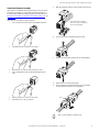
Contact and Connector Assembly
The procedure for assembling the 6-pin and 9-pin connectors is the same, except
that only the 9-pin connector has a clamp. Before you begin this procedure, you
must have all wires stripped and crimped. Depending on your configurations, see
Wire Selection and Preparation - 6-pin
, Wire Selection and Preparation - 9-pin, and
Crimp a Contact.
Follow these steps to assemble a rectangular connector.
1. Insert a crimped socket into the back of the (male) plug until it clicks.
2. Tug slightly on the wire to confirm it is set correctly.
3. Repeat this process for the rest of the sockets and set aside.
4. Insert a crimped pin into the back of the (female) receptacle until it
clicks.
5. Slightly tug on the wire to confirm it is set correctly.
6. Repeat this process for the rest of the pins.
7. Align and assemble the receptacle clamps around the 9-pin receptacle.
8. Insert the nuts into the assembled 9-pin receptacle clamp.
9. Thread the screws through the clamp, into the nut, and hand tighten.
10. Repeat this process for the 9-pin plug clamps.
11. Insert the receptacle into the plug until the two pieces latch together,
and verify that plug and receptacle are mated properly.
Cable is customer supplied, so cable type varies.
The receptacle clamp is intended to
relieve stress on pins caused by pulling
on the wires during handling.
Latch

8 Rockwell Automation Publication 2090-IN048B-EN-P - April 2020
Build Your Own Kinetix TLP Motor Cables Installation Instructions
Military-style Connectors
Military-style connector kits are available in 2-, 4-, 9-, and 17-pin configurations. All kits (catalog numbers 2090-KTxx-Mx-AA/AE) include a receptacle and receptacle body
and clamp. The 2090-KTxx-Mx-AE kits also include a plug and plug body and clamp. In this example, the 4-pin plug and receptacle is shown.
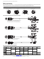
Figure 9 - Military-style Power/Brake Connector (standard) Cable Examples
IMPORTANT
The plug bushing and receptacle bushing are installed at the factory and must be removed before installing wires into the plug or receptacle.
Table 3 - Military-style Motor Power Flying-lead Dimensions
Cable AWG Connector Type
A
mm (in.)
B
mm (in.)
B1
mm (in.)
B2
mm (in.)
C
mm (in.)
D
mm (in.)
E
(1)
mm (in.)
(1) Strip lengths vary slightly depending on drive requirements. Refer to Additional Resources on page 12 for the drive user manual with specific values.
16
MC-type, power/brake
80.0 (3.15) 80.0 (3.15) – – 10.0 (0.39) 100 (3.94)
8.0 (0.31)
12
100 (3.94)
100 (3.94)
––
12.0 (0.47) 120 (4.72)
12
MD-type, power/brake
––
08
125 (4.92) 120 (4.72) 110 (4.33) –
125 (4.92)
06
ME-type, power only 115 (4.53) –
04 80.0 (3.15)
20MB-type, brake–80.0 (3.15)––––8.0 (0.31)
Plug
Receptacle
Receptacle Body and Clamp
Plug Body and Clamp
Contact
Plug Bushing
Receptacle Bushing
25.0
(0.98)
C
B
A
D
A
B
B1
B2
25.0
(0.98)
D
E
B
450
(17.7)
E
A
B
B1
B2
25.0
(0.98)
D
450
(17.7)
E
A
H
G
B
F
I
C
D
E
A
H
G
B
F
I
C
D
E
A
B
C
D
A
B
MC-type, 16 and 12 AWG power/brake cable with 2090-KTPC-MC-AA kit.
MD-type, 12 AWG power/brake cable with 2090-KTPC-MD-AA kit.
(these power/brake cables can also be assembled as power-only)
MD-type, 08 AWG power/brake cable with 2090-KTPC-MD-AA kit.
MD-type, 08 AWG power only cable with 2090-KTPC-MD-AA kit.
ME-type, power only cable with 2090-KTPC-ME-AA kit.
MB-type, brake cable with 2090-KTBK-MB-AA kit.

Rockwell Automation Publication 2090-IN048B-EN-P - April 2020 9
Build Your Own Kinetix TLP Motor Cables Installation Instructions
Figure 10 - Military-style Power/Brake Connector (extension) Cable Examples
Ring Lug Specifications
Ring lugs are recommended for motor power (U, V, W, and PE) wires as seen in Figure 9 on page 8. The following table describes the (customer-supplied) ring lugs for each
cable size. Ring lugs apply to only the PE conductor on 16…12 AWG cables.
Table 4 - Ring Lug Specifications
Power Cable Size
AWG
Non-insulated Ring Terminals Screw Size
18 RNB 1.25
#4
16 RNB 2
12 RNB 5.50
8RNB 8
6RNB 14#6
4RNB 22#8
A
H
G
B
F
I
C
D
E
A
H
G
B
F
I
C
D
E
A
H
G
B
F
I
C
D
E
A
H
G
B
F
I
C
D
E
A
B
C
D
A
B
C
D
A
B
A
B
MC-type, 16 and 12 AWG power/brake or power-only cable (with 2090-KTPC-MC-AE kit.
ME-type, 06 or 04 AWG power-only cable with 2090-KTPC-ME-AE kit.
MB-type, brake cable with 2090-KTBK-MB-AE kit.
MD-type, 12 or 08 AWG power/brake or power-only cable with 2090-KTPC-MD-AE kit.

10 Rockwell Automation Publication 2090-IN048B-EN-P - April 2020
Build Your Own Kinetix TLP Motor Cables Installation Instructions
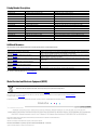
Wire Selection and Preparation
Standard contacts accept wire size ranges of 16…22 AWG, 12…14 AWG, 18…10 AWG, and 4…6 AWG. The insulation diameter range, strip length, and crimp height are
determined by the wire size and are shown below.
Table 5 - Strip Length Specifications
Wire Size
(AWG)
Strip Length (A)
mm (in.)
Strip Length (B)
mm (in.)
Typical Cable Conductors
20
7…9 (0.27…0.35)
60 (2.36)
16
12
08 8…10 (0.31…0.39)
06
16…18 (0.63…0.71)
04
Table 6 - Wire Selection
Kit Cat. No. Contact Size (pin number)
Applicable Wire Size
(1)
(1) Values represent the maximum wire size accepted by the connector pin/socket for each kit.
Outer Conductor Diameter
mm (in.)
IEC (mm
2
)
AWG, max
2090-KTBK-MB-AA
2090-KTBK-MB-AE
#16 (2) 1.25 20
1.95 (0.077)
2090-KTFB-MF-AA
2090-KTFB-MF-AE
#16 (17) 1.25 16
2090-KTPC-MC-AA
2090-KTPC-MC-AE
#12 (3) 4 12 2.95 (0.116)
#16 (6) 1.25 16 1.95 (0.077)
2090-KTPC-MD-AA
2090-KTPC-MD-AE
#8 (3) 6 10 3.5 (0.138)
#12 (6) 4 12 2.95 (0.116)
2090-KTPC-ME-AA
2090-KTPC-ME-AE
#4 (4) 22 4 5.19 (0.204)

Rockwell Automation Publication 2090-IN048B-EN-P - April 2020 11
Build Your Own Kinetix TLP Motor Cables Installation Instructions
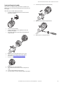
Contact and Connector Assembly
The procedure for assembling the military-style connectors, regardless of pin
number or size, is the same. Before performing this procedure, you must have all
wires stripped.
Follow these steps to assemble a military-style connector.
1. Loosen (do not remove) the hardware that attaches the receptacle
bushing to the receptacle.
2. Unscrew the receptacle bushing.
3. Install heat shrink tubing (customer supplied) on each wire to be
installed in the receptacle.
4. Insert the wires through the receptacle body, and then through the
receptacle bushing.
5. Rotate the wire contact and insert the wire as far as it goes.
6. Solder the wire to the termination point using the soldering
specifications in Strip Length Specifications
on page 10.
7. Rotate the contact so the soldering gap faces inward.
8. Repeat this process for the remaining wires.
9. Slide each heat shrink tube forward to cover the solder points and
shrink.
10. Screw the receptacle bushing onto the receptacle.
11. Insert the hardware to secure the receptacle bushing to the receptacle.
12. Screw the receptacle body to the receptacle bushing.
13. Secure the receptacle body with supplied hardware.
14. Repeat this process for the plug connection.

Publication 2090-IN048B-EN-P - April 2020 | Supersedes Publication 2090-IN048A-EN-P - October 2019
Copyright © 2020 Rockwell Automation, Inc. All rights reserved. Printed in the U.S.A.
Rockwell Otomasyon Ticaret A.Ş. Kar Plaza İş Merkezi E Blok Kat:6 34752 İçerenkÖy, İstanbul, Tel: +90 (216) 5698400 EEE YÖnetmeliğine Uygundur
Allen-Bradley, expanding human possibility, Kinetix, Rockwell Automation, and Rockwell Software are trademarks of Rockwell Automation, Inc.
EtherNet/IP is a trademark of ODVA, Inc.
Trademarks not belonging to Rockwell Automation are property of their respective companies.
Your comments help us serve your documentation needs better. If you have any suggestions on how to improve our content, complete the form at rok.auto/docfeedback.
For technical support, visit
rok.auto/support.
Waste Electrical and Electronic Equipment (WEEE)
Rockwell Automation maintains current product environmental information on its website at rok.auto/pec.
At the end of life, this equipment should be collected separately from any unsorted municipal waste.
Catalog Number Descriptions
Additional Resources
These documents contain additional information concerning related products from Rockwell Automation.
You can view or download publications at rok.auto/literature.
Catalog Number Motors Description
2090-KTPC-MA-AA TLP-A046, TLP-A070, TLP-A090, TLP-A100 Kinetix TLP motor power connector kit (plug)
2090-KTPC-MC-AA TLP-A115, TLP-A145 Kinetix TLP motor power connector kit (plug)
2090-KTPC-MD-AA TLP-A200 (4.5 kW and smaller) Kinetix TLP motor power connector kit (plug)
2090-KTPC-ME-AA TLP-A200 (5.5 kW and 7.5 kW) and TLP-A235 Kinetix TLP motor power connector kit (plug)
2090-KTPC-MA-AE TLP-A046, TLP-A070, TLP-A090, TLP-A100 Kinetix TLP motor power extension connector kit (plug and socket)
2090-KTPC-MC-AE TLP-A115, TLP-A145 Kinetix TLP motor power extension connector kit (plug and socket)
2090-KTPC-MD-AE TLP-A200 (4.5 kW and smaller) Kinetix TLP motor power extension connector kit (plug and socket)
2090-KTPC-ME-AE TLP-A200 (5.5 kW and 7.5 kW) and TLP-A235 Kinetix TLP motor power extension connector kit (plug and socket)
2090-KTFB-MA-AA TLP-A046, TLP-A070, TLP-A090, TLP-A100 Kinetix TLP motor feedback connector kit (plug)
2090-KTFB-MF-AA TLP-A115, TLP-A145, TLP-A200, TLP-A235 Kinetix TLP motor feedback connector kit (plug)
2090-KTFB-MA-AE TLP-A046, TLP-A070, TLP-A090, TLP-A100 Kinetix TLP motor feedback extension connector kit (plug and socket)
2090-KTFB-MF-AE TLP-A115, TLP-A145, TLP-A200, TLP-A235 Kinetix TLP motor feedback extension connector kit (plug and socket)
2090-KTBK-MB-AA TLP-A200 (5.5 kW and 7.5 kW) and TLP-A235 Kinetix TLP motor brake connector kit (plug)
2090-KTBK-MB-AE TLP-A200 (5.5 kW and 7.5 kW) and TLP-A235 Kinetix TLP motor brake extension connector kit (plug and socket)
Resource Description
Kinetix Servo Drives Specifications Technical Data,
publication KNX-TD003
Provides product specifications for the Kinetix® Integrated Motion over EtherNet/IP™ network, Integrated Motion
over Sercos interface, EtherNet/IP networking, and component servo drive families.
Kinetix Motion Accessories Specifications Technical Data,
publication KNX-TD004
Provides product specifications for 2090-Series motor and interface cables, low-profile connector kits, drive power
components, and other servo drive accessory items.
2090-Series Cables for Kinetix TLP Servo Motors Installation Instructions,
publication 2090-IN046
Provides information on how to install 2090-Series motor standard non-flex and continuous-flex power/brake and
feedback cables.
Kinetix 5100 EtherNet/IP Indexing Servo Drives User Manual,
publication 2198-UM004
Information on how to install, configure, start, and troubleshoot your Kinetix 5100 servo drive system.
Industrial Automation Wiring and Grounding Guidelines,
publication 1770-4.1
Provides general guidelines for installing a Rockwell Automation industrial system.
Product Certifications website rok.auto/certifications
Provides declarations of conformity, certificates, and other certification details.
-
 1
1
-
 2
2
-
 3
3
-
 4
4
-
 5
5
-
 6
6
-
 7
7
-
 8
8
-
 9
9
-
 10
10
-
 11
11
-
 12
12


Rockwell Automation Allen-Bradley 2090-KTFB-MA-AE Installation Instructions Manual
- Type
- Installation Instructions Manual
Ask a question and I''ll find the answer in the document
Finding information in a document is now easier with AI
Related papers
-
 Rockwell Automation Allen-Bradley 2090-KTFB-MA-AE Installation Instructions Manual
-
 Rockwell Automation Allen-Bradley Kinetix 2090-CTPW-MEDF Installation Instructions Manual
-
 Rockwell Automation Allen-Bradley Kinetix TLP-A100-100 Installation Instructions Manual
-
 Rockwell Automation Allen-Bradley TLP-SSN-F046 Installation Instructions Manual
-
 Rockwell Automation Allen-Bradley Kinetix 5100 Migration Manual
-
 Rockwell Automation Allen-Bradley 2198-E2075-ERS Migration Manual
-
 Rockwell Automation Allen-Bradley 2198-KTBT Installation guide
-
Rockwell Automation 2198-C1015-ERS Installation Instructions Manual
-
 Rockwell Automation Allen-Bradley 2198-H070-ERS User manual
-
Ultra Start Allen-Bradley Kinetix 3 2071-AP0 User manual


Other documents
-
Xtech XTC-300 Datasheet
-
Ideal In-Sure® Push-In Wire Connector, Model 90 8-Port Black Operating instructions
-
Ideal 30-088J User manual
-
Ideal 30-090J Operating instructions
-
3M Scotchlok™ Carbon Steel Scissor TH-450, features crimp stations 26 to 6 awg connectors User guide
-
-
-
Ideal In-Sure® Push-In Wire Connector, Model 32 2-Port Red Installation guide
-
-
Ideal In-Sure 32 User manual