Moxa Technologies UC-2114-T-LX Quick Install Guide

Type
Quick Install Guide

This manual is also suitable for

P/N: 1802021000211
*1802021000211*
UC-2100-W Series
Quick Installation Guide
Version 2.0, October 2019
Technical Support Contact Information
www.moxa.com/support
Moxa Americas:
Toll
-free: 1-888-669-2872
Tel:
1-714-528-6777
Fax:
1-714-528-6778
Moxa China (Shanghai office):
Toll
-free: 800-820-5036
Tel:
+86-21-5258-9955
Fax:
+86-21-5258-5505
Moxa Europe:
Tel:
+49-89-3 70 03 99-0
Fax:
+49-89-3 70 03 99-99
Moxa Asia-Pacific:
Tel:
+886-2-8919-1230
Fax:
+886-2-8919-1231
Moxa India:
Tel:
+91-80-4172-9088
Fax:
+91-80-4132-1045
2019 Moxa Inc. All rights reserved.
- 2 -
Overview
The UC-2100-W Series computing platform is designed for embedded
data acquisition and processing applications. The computer comes with
up to two software-selectable RS-232/422/485 full-signal serial ports
and single or dual Ethernet LAN ports. In addition, the Arm-based
computing platform is available in various models that can fulfill diverse
interface requirements, such as dual serial, LAN ports, and wireless
connections. These versatile communication capabilities let users
efficiently adapt the palm-sized computing platform to a variety of
complex communications solutions.
Model Names and Package Checklist
The UC-2100-W Series includes the following models:
UC-2114-T-LX
UC-2116-T-LX
Before installing a UC-2100-W computer, verify that the package
contains the following items:
UC-2100-W Series computer
Console cable
Power jack
Quick Installation Guide (printed)
Warranty card
Notify your sales representative if any of the above items are missing
or damaged.
NOTE
The console cable and power jack can be found inside the
product box, beneath the molded-pulp cushion.
- 3 -
Appearance
UC-2114
UC-2116
- 4 -
LED Indicators
The function of each LED is described in the table below:
Status
Function
Green
Power is on, and the device is
functioning normally
Off
Power is off
(10/100 Mbps)
Green
Steady On: 10 Mbps Ethernet link
Blinking: Data transmission is in
progress
Yellow
Steady On: 100 Mbps Ethernet link
Blinking: Data transmission is in
progress
Off
Speed lower than 10 Mbps or the
cable is not connected
(10/100/1000
Mbps)
Green
Steady On: 100 Mbps Ethernet link
Blinking: Data transmission is in
progress
Yellow Steady On: 1000 Mbps Ethernet link
Blinking: Data transmission is in
progress
Off
Speed lower than 10 Mbps or the
cable is not connected
Green
Serial port is transmitting data
Off
Serial port is not transmitting data
Serial (Rx)
Yellow
Serial port is receiving data
Off
Serial port is not receiving data
Green/Yellow
User Programmable
indicate the
Wireless
signal strength
Yellow
The number of glowing LEDs
indicates the signal strength
3 LEDs: Excellent
2 LEDs : Good
1 LED : Poor
Off
Wireless module is not detected
Green
CAN port is transmitting data
Off
CAN port is not transmitting data
Green
CAN port is receiving data
Off
CAN port is not receiving data
Reset Button
The UC-2100-W Series computer is provided with a reset button, which
is located on the top panel of the computer. To reboot the computer,
press the reset button less than 1 second. Press and hold the reset
button between 7 to 9 seconds to reset the computer to the factory
default settings. When the reset button is held down, the User LED will
blink twice every second. The User LED will become steady when you
hold the button continuously for 7 to 9 seconds. Release the button
within this period to load the factory default settings.
- 5 -
Installing the Computer
Wall or Cabinet Mounting
Use two screws per side to mount the UC-2100-W Series on a wall or
inside a cabinet.
Wiring Requirements
Be sure to read and follow these common safety precautions before
proceeding with the installation of any electronic device:
Use separate paths to route wiring for power and devices. If power
wiring and device wiring paths must cross, make sure the wires are
perpendicular at the intersection point.
NOTE
Do not run signal or communication wiring and power wiring in
the same wire conduit. To avoid interference, wires with
different signal characteristics should be routed separately.
Use the type of signal transmitted through a wire to determine
which wires should be kept separate. The rule of thumb is that
wiring that shares similar electrical characteristics can be bundled
together.
Keep input wiring and output wiring separate.
It is strongly advised that you label wiring to all devices for easy
identification.
ATTENTION
This equipment is intended to be used in Restricted Access
Locations.
Safety First!
Be sure to disconnect the power cord before installing and/or
wiring your
UC-2100-W Series computers.
Wiring Caution!
Calculate the maximum possible current in each power wire
and common wire. Observe all electrical codes dictating the
maximum current allo
wable for each wire size. If the current
goes above the maximum ratings, the wiring could overheat,
causing serious damage to your equipment.
- 6 -
CAUTION
Be careful when handling the unit. When the unit is plugged in,
the internal components generate
heat, and consequently the
outer casing may feel hot to the touch.
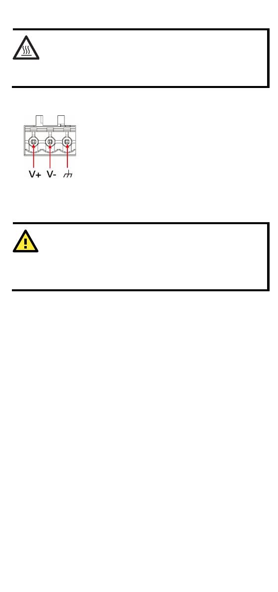
Connecting the Power
Connect the 9 to 48 VDC power line to the
terminal block, which is connected to the UC-
2100-W Series computer. If the power is
supplied properly, the “Power” LED will glow a
solid green light. The power input location and
pin definition are shown in the adjacent
diagram. The input terminal block (CN5) is
suitable for a wire size of 12 to 30 AWG (3.3 to
0.05 mm
2
) and a torque value of 0.5 N-m
(4.425 lb-in).
I
MPORTANT
This product is intended to be supplied by a UL Listed power
adapter
or DC power source whose output meets SELV/LPS.
The power source must be
rated 9 to 48 VDC, minimum 0.6 A,
and minimum Tma = 75°C.
Grounding the Unit
Grounding and wire routing help limit the effects of noise due to
electromagnetic interference (EMI). Run the ground connection from
the terminal block connector to the grounding surface prior to
connecting the power. Please note that this product is intended to be
mounted on a well-grounded mounting surface, such as a metal panel.
The minimum cross-sectional area of the earthing conductor shall be
equal to the input wiring cable.
Connecting to the Console Port
The UC-2100-W console port is a 4-pin pin-header RS-232 port located
on the right panel of the case. It is designed for serial console
terminals, which are useful for viewing the boot up message, or for
debugging system boot up issues. Remove the protective cover on the
port to connect the console cable.
- 7 -
Serial Console Port & Pinouts
Serial Console Cable
Pin
Signal
1
TxD
2
RxD
3
NC
4
GND
Connecting to the Network
The Ethernet ports are located on the top or bottom panel of the UC-
2100-W computers. The pin assignments for the Ethernet port are
shown in the following figure. If you are using your own cable, make
sure that the pin assignments on the Ethernet cable connector match
the pin assignments on the Ethernet port.
Pin
10/100 Mbps
10/100/1000 Mbps
1
Tx+
TRD(0)+
2
Tx-
TRD(0)-
3
Rx+
TRD(1)+
4
TRD(2)+
5
TRD(2)-
6
Rx-
TRD(1)-
7
TRD(3)+
8
TRD(3)-
Connecting to a Serial Device
The serial ports are located on the bottom panel
of the
UC-2100-W computer. Use a serial cable
to
connect your serial device to the computer’s
ser
ial port. These serial ports have male DB9
connectors and can be configured for RS
-232,
RS
-422, or RS-485 communication. The pin
location and assignments are shown in the
following table.
Pin RS-232 RS-422
RS-485
(4-wire)
RS-485
(2-wire)
1
DCD
TxDA(-)
TxDA(-)
2
RxD
TxDB(+)
TxDB(+)
3
TxD
RxDB(+)
RxDB(+)
DataB(+)
4
DTR
RxDA(-)
RxDA(-)
DataA(-)
5
GND
GND
GND
GND
6
DSR
7
RTS
8
CTS
- 8 -
Connecting to a CAN Device
The UC-2114 and UC-2116 come with two CAN ports, which use the 5-
pin terminal block and are compatible with the CAN 2.0A/B standard.
The pin assignment of the port is shown below.
Pin
Signal
1
GND
2
L
3
Chassis
4
H
5
Vout
Installing SIM Cards
You will need to install a SIM card on your UC-2100-W computer.
Follow these steps to install the SIM card.
1. Remove the screw on the cover located
on the right panel.
2. Insert the SIM card into the socket.
Make sure you place the chip-side on
the bottom.
3. To remove the SIM card, simply push
the SIM card and release it.
Installing the microSD Card
Both UC-2114 and UC-2116 come with a storage socket that allows
users to install one microSD card. Follow these steps to install the
microSD card:
1. The microSD socket is located
below the
right panel of the computer. Unfasten
the screw and remove the right panel
cover.
2. Insert the microSD card into the socket
.
Ensure that the card is inserted in the
right direction.
3. Replace the cover and fasten the screw
on the cover to secure the cover.
To remove the
microSD
card, simply push the
card in and release it.
Adjusting the DIP Switch
The UC-2114 and UC-2116 computers come with one DIP switch for
users to adjust the serial port parameters. To set up the DIP switch, do
the following:
- 9 -
1. Remove the screws on the DIP switch cover
located on the rear panel of the computer.
2. Remove the thin film on the DIP switch and
adjust the setting as required.
Refer to the table below for the DIP switch
settings. The default value is OFF.
SW
1
2
3
4
Low
High
Term.
ON
1
1
120 Ω
OFF
150
150
Real-time Clock
The real-time clock in the UC-2100-W is powered by a lithium battery.
We strongly recommend that you do not replace the lithium battery
without the help of a Moxa support engineer. If you need to change the
battery, contact the Moxa RMA service team.
ATTENTION
There is a risk of explosion if the battery is replaced wi
th an
incorrect type of battery
.
Accessing the UC-2100-W Using a PC
You can use a PC to access the UC-2100-W by one of the following
methods:
A. Through the serial console port with the following settings:
Baudrate = 115200 bps, Parity = None, Data bits = 8, Stop bits
= 1, Flow Control = None.
ATTENTION
Remember to choose the “VT100” terminal type. Use the
console cable to connect a PC to the UC
-2100-W's serial
console port
.
B. Using SSH over the network.
Refer to the following IP addresses and login information:
Default IP Address
Netmask
LAN 1
192.168.3.127
255.255.255.0
LAN 2
192.168.4.127
255.255.255.0
Login: moxa
Password: moxa
  • Page 1 1
  • Page 2 2
  • Page 3 3
  • Page 4 4
  • Page 5 5
  • Page 6 6
  • Page 7 7
  • Page 8 8
  • Page 9 9

Moxa Technologies UC-2114-T-LX Quick Install Guide

Type
Quick Install Guide
This manual is also suitable for

Ask a question and I''ll find the answer in the document

Finding information in a document is now easier with AI