Page is loading ...

SD-802XAI (NZ319) Page 1Texmate, Inc.Tel. (760) 598-9899 • www.texmate.com
• Friendly front panel programming.
• Intuitive, user friendly calibration procedures.
• Single input channel with dual totalizers for sub and grand total
processing.
• Smart digital filtering and programmable input averaging with
averaging window for quick response time to large signal
changes.
• Three external inputs using contact closures for resetting total-
izer 1, totalizer 2, or preventing programming changes.
• One independent programmable setpoint.
• Setpoint activated from input or selected meter function.
• Setpoint hysteresis or deviation mode settings.
• Seven (7) relay timer modes.
• Single 210 mA, 400 VDC solid state relay (SSR).
• Relay latching.
• Manual relay reset.
• Programmable safety lockout to prevent tampering.
• Peak and valley retention.
• Optional NEMA-4 front cover.
• Square root extraction.
General Features
Calibration Mode . . . . . . . . . . . . . . . . . . . . . . . . . . . . . . . . . . . . . .6
Case Dimensions . . . . . . . . . . . . . . . . . . . . . . . . . . . . . . . . . . . . .48
Connector Pinouts . . . . . . . . . . . . . . . . . . . . . . . . . . . . . . . . . . . .42
Contrast Mode . . . . . . . . . . . . . . . . . . . . . . . . . . . . . . . . . . . . . . . .6
Controls and Indicators . . . . . . . . . . . . . . . . . . . . . . . . . . . . . . . . . .2
Custom Faceplates . . . . . . . . . . . . . . . . . . . . . . . . . . . . . . . . . . . .43
Customer Code Settings . . . . . . . . . . . . . . . . . . . . . . . . . . . . . . . .45
Display 1 Source Mode . . . . . . . . . . . . . . . . . . . . . . . . . . . . . . . . .18
Display 2 Source Mode . . . . . . . . . . . . . . . . . . . . . . . . . . . . . . . . .20
Display Format Mode . . . . . . . . . . . . . . . . . . . . . . . . . . . . . . . . . .22
Document Revision History . . . . . . . . . . . . . . . . . . . . . . . . . . . . . .48
Push-buttons
Optional
Touch-Pad
Standard
SD-Series
INTERNATIONAL
CASES
DIN
1/8
1/32
1/32
The 1/8 DIN case style and panel appearance
of the SD-802XAI meter matches Texmate’s
range of Lynx, Leopard, and Tiger 320 Series
meter families. The depth behind the panel is
only 15 mm (0.59”), increasing to just 27.5 with
a connector attached. The SD-802XAI makes
an ideal extra or remote display as it can oper-
ate in conjunction with the 4-20 mA loop input,
or from the 4-20 mA analog output of most
Leopard or Tiger 320 Series meters.
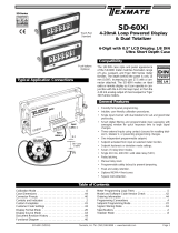
Compatibility
SD802X
N.O.
COM
GND
LOCK
RST2
-4/20MA
+4/20MA
RST1
SSR Output
100 mA Load Max.
(+)
(–)
Input
LOW (–)
Input
HIGH (+)
Typical Application Connections
24 V Loop
Supply
Table of Contents
Dual 8-Digit, 5.5mm
High Dot Matrix LCD Display,
1/8 DIN Ultra Short Depth Case
SD-802XAI
4-20mA Loop Powered Dual
Display with Dual Totalizer
Functional Diagram . . . . . . . . . . . . . . . . . . . . . . . . . . . . . . . . . . . .42
Meter Programming Logic Trees . . . . . . . . . . . . . . . . . . . . . . . . . . .5
Model and Software Code Version Check . . . . . . . . . . . . . . . . . . .44
Ordering Information . . . . . . . . . . . . . . . . . . . . . . . . . . . . . . . . . . .48
Programming Conventions . . . . . . . . . . . . . . . . . . . . . . . . . . . . . . .4
Setpoint Programming Mode . . . . . . . . . . . . . . . . . . . . . . . . . . . . .24
Signal Filtering Mode . . . . . . . . . . . . . . . . . . . . . . . . . . . . . . . . . .16
Specifications . . . . . . . . . . . . . . . . . . . . . . . . . . . . . . . . . . . . . . . . .2
Totalizer Mode . . . . . . . . . . . . . . . . . . . . . . . . . . . . . . . . . . . . . . . .8

Weight: ...........................56.7 gms (2 oz)
141.7 gms (5 oz) when packed
Case Material: ..............Polycarbonate
Lens Cover: ..................NEMA-4, (optional)
Underrange Indication:..Input signal below approx. 3.3 mA dis-
plays [LOW input] reading
Overrange Indication:....Input signal above approx.27.7 mA dis-
plays [OVER] reading
Programming Buttons
PROGRAM: ..................Move from one program step to the next
UP: ................................Increase the value of the displayed
parameter
DOWN: ..........................Decrease the value of the displayed
parameter
Application Functions
Totalizer: ........................Two totalizers are available.The totalizer
calculates the running total of a process
signal being metered by accumulating an
input process variable over time
Peak and Valley:............The meter can retain peak and valley
(min/max) information and recall this on
the front panel
Setpoints: ......................SP1 resets a selected function and / or
activates Relay 1
Prog
Front Panel Controls and Indicators
Prog
UP Button
DOWN Button
PROGRAM
Button
Controls and Indicators
Texmate, Inc. Tel. (760) 598-9899 • www.texmate.comPage 2 SD-802XAI (NZ319)
Specifications
Input Configuration: ......Series connection to 4-20 mA DC current
loop. 3.4 volts drop plus 20 Ω(equivalent
to 3.9 V @ 20 mA), plus 2.3 V drop if
Single solid state relay (SSR) installed
Relay Output: ................. SSR. Max 210 mA, 400 VDC ONLY
Display: ..........................Dual 8-digit, 5.5 mm high, 5 x 8 format
dot-matrix Liquid Crystal Display (LCD)
Polarity: ..........................Assumed positive, displays – negative
Display Range: ............–9900000 to 9900000
Display Update: ............0.5 secs
Internal Resolution: ......16-bits
A/D Converter: ..............16-bit Sigma Delta
Accuracy (Standard): ....±0.02% of reading ± 2 digit (typical)
Conversion Rate: ..........10 samples per second
Temp.Coefficient:..........Typically 30 ppm/ °C
Descriptors:....................Any ASCII character selectable
Decimal Point:................Front panel, user programmable to seven
positions
Operating Temperature:-10°C to +50°C
Storage Temperature:....-20˚C to +70˚C
Warm Up Time: ............1 minute
Relative Humidity:..........95% (non-condensing)
Case Dimensions: ........1/8 DIN, Bezel: 96x48 mm (3.78”x1.89”).
Depth behind bezel 15 mm (0.59”) plus
16.4 mm (0.65”) for right-angled connector
While programming, pressing the button saves the current
programming settings and moves on to the next programming
step or mode.
To save a new mode configuration setting and return to the
operational display, press the button once and then press
the and buttons at the same time.
You can move through the programming modes using the
button while [Skip] toggles with the mode name.The modes you
pass are not affected unless you enter using the button and
make changes using the or buttons.
Prog
Prog
Prog
Prog
Program Button
Pressing the and
buttons at the same time
enters the main program-
ming mode. This allows
you to configure the meter’s
main functions.
Prog
Calibration Mode
Totalizer Mode
To Enter Mode
Prog
Contrast Mode
Prog
Prog
To adjust
contrast
from 1 to 7
Signal Filtering Mode
Display 1 Source Mode
Display Format Mode
To Enter Mode
To Enter Mode
To Enter Mode
Display 2 Source Mode
To Enter Mode
Prog
Prog
Prog
Prog
To Enter Mode
Prog
Prog
Setpoint Activation Value Mode
Setpoint Control Settings Mode
To increase SP activation
value (max 999999)
To decrease SP activation
value (min -199999)
Set the three digits to
the required setpoint
control settings
Follow the Setpoint
Setup Sequence when
setting setpoint control
functions
Signal
BELOW
3.3 mA
Signal
ABOVE
27.7 mA
Pressing the and buttons at the same time enters the
setpoint programming mode.
Prog
Display 1
Display 2

SD-802XAI (NZ319) Page 3Texmate, Inc. Tel. (760) 598-9899 • www.texmate.com
1) The scaling requirement exceeded
the capability of the meter (–9900000
to +9900000).
2) No input signal present, or no differ-
ence between low and high input dur-
ing calibration.
3) Incorrect connections.
Low Input Message
The [Low Input] message occurs
when the current loop current is
enough to light the display, but not
enough to drive the meter software.
This occurs at approximately 3.3 mA.
OVER Message
The [OVER] message occurs when the
current loop current goes overrange.
This occurs at approximately 27.7 mA.
After 2 seconds
Last Digit ASCII Character Set
Prog
Press
once
View Total 1
View Peak
View Rate
Prog
Operational Display
Operational Display
Up Button
When setting a displayed param-
eter during programming, press
the button to increase the
value of the displayed parameter.
UP Button View Mode
When in the operational display,
pressing the button initiates a
viewing mode that allows you to
view the readings on total 1,
peak, and channel 1. Once into
the viewing mode, pressing the
button moves through each
displayed parameter.
Press the button to return to
the operational display.
Prog
Down Button
When setting a displayed param-
eter during programming, press
the button to decrease the
value of the displayed parameter.
DOWN Button View Mode
When in the operational display,
pressing the button initiates a
viewing mode that allows you to
view the readings on total 2, val-
ley, and setpoint 1. Once into the
viewing mode, pressing the
button moves through each dis-
played parameter.
Press the button to return to
the operational display.
Prog
View Total 2
View Valley
View Setpoint 1
Prog
Press
once
Prog
Operational Display
Operational Display
Display 1 is the top display of eight dig-
its in a 5 x 8 dot-matrix LCD format.
Display 2 is the bottom display of eight
digits in a 5 x 8 dot-matrix LCD format.
Displays 1 and 2 are used to display the
meter input signal readings. They also
display the configuration setup modes
and settings during programming.
After 2 seconds
Error 1 Message
An Error 1 message can occur during calibration procedures.
The bottom display reads [Error 1] for about 2 seconds and
then returns to the [Skip] [Cal_Rate] display. The three most
likely causes of an error 1 message are:
Programming Lockout Pin
Rear Panel Controls and Indicators
Prog
Prog
Totalizer 1 Reset Pin
When connected to the GND pin, the RST1 pin resets totalizer
1 to zero.
Totalizer 2 Reset Pin
When connected to the GND pin, the RST2 pin resets totalizer
2 to zero.
One of the following ASCII characters
can be selected as a descriptor in the
last digit of either display. The arrows
show the order the characters appear
when pressing the button during pro-
gramming.
When connected to the GND
(ground) pin, the LOCK pin prevents
any programming changes being
made to the meter, except to the
contrast.
If an attempt is made to enter the
main programming mode, the
meter enters the contrast mode and
allows the contrast to be changed.
Dual Dot-matrix LCD Displays
Pressing the button again displays the word [Locked].
Further pressing of the button displays the programming
modes but settings cannot be changed.
Attempting to enter the setpoint programming mode immedi-
ately displays the word [Locked]. Further pressing the but-
ton enters the setpoint programming mode but settings cannot
be changed.
Prog
Prog
Prog

Prog
To explain software configuration procedures, diagrams are used
to visually describe the programming steps.The following conven-
tions are used to represent the buttons and indicators on the meter,
and the actions involved in programming the meter:
Text or numbers shown between square brackets
in a description or procedure indicate the pro-
gramming mode name of the function or the value
displayed on the meter display.
Symbol Explanation
Prog
This symbol represents the OPERATIONAL
DISPLAY. After the meter has been powered
up, the display settles and indicates the cali-
brated input signal.This is known as the oper-
ational mode and is generally referred to as the
operational display throughout this document.
This symbol represents the UP button.
Shown in a diagram, pressing the UP button is
always indicated by a right hand.
This symbol represents the DOWN button.
Shown in a diagram, pressing the DOWN but-
ton is always indicated by a right hand.
Where two right hands are shown on the same
diagram with the word OR between them, this
indicates that both the and buttons can
be used to adjust the display:UP for increase,
DOWN for decrease.
This symbol represents the PROGRAM button.
In a procedure, pressing the program button is
always indicated by a left hand. A number indi-
cates how many times it must be pressed and
released.
[Span]
[10000]
Where a number is not
definable, the default set-
ting [000] is shown.
Programming Conventions
XX
Where a left and right hand are shown on separate buttons on
the same diagram, this indicates that the buttons must be
pressed at the same time.
Programming Procedure Diagrams
The programming procedures described in this manual are
graphic based diagrams with little descriptive text.
Each procedure shows a number of meter panel displays running
in procedural steps from the top to the bottom of the page.
If need be, the procedure may run into two columns with the left
column running down the page and continuing at the top of the
right-hand column.Each action performed by the user is shown as
a numbered step.
Each procedural step shows the meter display as it looks before an
action is performed.The hand or hands in the procedural step indi-
cate the action to be performed and also how many times, or for
how long, the button is to be pressed.
For example, the diagram below shows the meter in the opera-
tional display. With a left hand pressing the button and a
right hand pressing the button, the user is entering the main
programming mode.
Prog
The meter uses a set of intuitive
software modes to allow maximum
user flexibility while maintaining an
easy programming process. When
configuring the setpoint program-
ming mode, the meter uses the
three right-hand side display digits
on the top display (display 1).These
are known as the first, second, and
third digits and can be seen in the
diagram opposite.
Setpoint Control Mode
1st
Digit 2nd
Digit 3rd
Digit
Prog
Press
1
Operational Display
Prog
Contrast Mode
Prog
Press
at same
time
Press
at same
time
Press
1
Prog
OR
All programming modes are entered from this level.
If an X appears in the description of a 3-
digit setpoint programming mode proce-
dure, this means that more than one
choice can be made, or any number dis-
played in that digit is not relevant to the
function being explained.
Texmate, Inc. Tel. (760) 598-9899 • www.texmate.comPage 4 SD-802XAI (NZ319)
This is indicated by the
next diagram displaying
[5] and [Contrast]. This
is the first configuration
mode of the main pro-
gramming mode.

SD-802XAI (NZ319) Page 5Texmate, Inc. Tel. (760) 598-9899 • www.texmate.com
The main and setpoint programming modes are accessible
from the operational display.
Main Programming Mode
Meter Programming Logic Trees
Setpoint Programming Mode
Calibration Mode
Totalizer Mode
Signal Filtering Mode
Display 1 Source Mode
Display Format Mode
To Enter Mode
To Enter Mode
To Enter Mode
To Enter Mode
Contrast Mode
Display 2 Source Mode
To Enter Mode
Prog
Prog
Prog
Prog
Prog
Prog
To Enter Mode
To adjust
contrast
from 1 to 7
Prog
Main
Programming
Mode
Press
at same
time
Press
at same
time
Prog
Prog
Setpoint Control Settings Mode
To increase SP activation
value (max 999999)
To decrease SP activation
value (min -199999)
Set the three digits to
the required setpoint
control settings
Follow the Setpoint
Setup Sequence when
setting setpoint control
functions
Prog
Setpoint
Programming
Mode
Press
at same
time
Press
at same
time
Setpoint Activation
Value Mode
Prog
Press
once
View Total 1
View Peak
View Rate
Prog
Operational Display
Operational Display
View Total 2
View Valley
View Setpoint 1
Prog
Press
once
Prog
Operational Display
Operational Display
View Modes
While in the operational display, pressing the button allows
you to view but not change the following parameters:
•The current value in totalizer 1.
•The current peak value.
•The current display on rate.
•The current value in
totalizer 2.
•The current valley
reading.
•The current activation
setting for setpoint 1.
Note:
While in the total 1
view mode, pressing
the and buttons
at the same time resets
totalizer 1 to 0 (zero).
While in the peak view
mode, pressing the
and buttons at the
same time resets peak
to the current input sig-
nal display reading.
Note:
While in the total 2
view mode, pressing
the and buttons
at the same time resets
totalizer 2 to 0 (zero).
While in the valley view
mode, pressing the
and buttons at the
same time resets valley
to the current input sig-
nal display reading.
While in the operational display, pressing the button allows
you to view but not change the following parameters:
The setpoint programming
mode provides access to
program all setpoint 1 acti-
vation and control functions.
The main programming
mode provides access to
program all meter functions,
except setpoints.

Texmate, Inc. Tel. (760) 598-9899 • www.texmate.comPage 6 SD-802XAI (NZ319)
Contrast Mode
Press the and buttons at the same time to enter the main programming
mode. The contrast mode is the first mode that appears.This mode allows you
to adjust the display contrast in a range from 1 to 7, with 1 being the least contrast
and 7 being the most contrast.While in this mode, pressing the button increas-
es the contrast and pressing the button decreases the contrast.
Prog
Calibration Mode
Totalizer Mode
Signal Filtering Mode
Display 1 Source Mode
Display Format Mode
Max 9900000
To Enter Mode
To Enter Mode
To Enter Mode
Contrast Mode
Display 2 Source Mode
To Enter Mode
Prog
Prog
Prog
Prog
Prog
Prog
To Enter Mode
To adjust
contrast
from 1 to 7
Prog
Prog
Prog
Prog
To adjust
Zero setting
To adjust
Span setting
Calibration Mode
Prog
Min –9900000
Max 9900000
Min –9900000
Prog
Main
Programming
Mode
Press
at same
time
Press
at same
time
Prog
LOW
Signal HIGH
Signal
Prog
OR
Prog
OR
Example Procedure
The following example procedure shows how to cali-
brate the input signal from 0 to 5,000 counts for a linear
signal in the 50 Hz input frequency range.
Calibration Mode
The calibration mode follows the contrast mode. It
allows you to:
•Select input frequency rejection of 50 or 60 Hz.
•Select linear or square root response.
•Scale the input signal through zero and span settings.
Noise Rejection Selection
Press the button to enter the calibration mode.The
first setting displayed is the noise rejection setting
[Frequency] [50 hZ]. This setting allows you to chose
between 50 and 60 Hz noise rejection.
Response Setting
After selecting the noise rejection setting, press the
button to enter the response setting [Response] [Linear].
Input Signal Scaling
This is a two-point calibration procedure that requires a
low and high input signal source for calibrating the zero
and span settings.
After selecting the response setting, press the button
to enter the zero setting [Zero] [0]. Apply the low input
source to the meter and, using the and buttons, set
the zero setting between –9900000 and 9900000 counts.
When the zero setting has been set, press the button
to enter the span setting [Span] [20000].
Now apply the high input source to the meter and, using the
and buttons, set the high setting between
–9900000 and 9900000 counts.
Prog
Prog
Prog

SD-802XAI (NZ319) Page 7Texmate, Inc. Tel. (760) 598-9899 • www.texmate.com
Calibration Mode continued
From Step 9
To Step 10
LOW
Signal
HIGH
Signal
Step 4
Enter the
Calibration Mode
Step 5
Select the required
noise rejection setting
(50 or 60 Hz)
Step 7
Select the required linear
response setting
and enter the zero input
mode
Step 9
9.1. Adjust the display to the
desired reading for the zero
input
9.2. Apply the LOW input
signal
Step 11
11.1. Adjust the display to the
desired reading for the span
input
11.2. Apply the HIGH input
signal
Step 10
Save the reading for the
zero load input into the
meter and enter the
span mode
Step 12
Save the calibration
settings
Skip the Display Format
Mode to return to the
operational display
Step 1
Enter the Main
Programming
Mode
Step 2
Skip the Contrast
Mode
Step 14
Step 15
Skip the Signal
Filtering Mode
Skip the Totalizer Mode
Step 16
Skip the Display 1
Source Mode
Step 18
Operational Display
Prog
Contrast Mode
Prog
Press
at same
time
Press
at same
time
Press
1
Step 3
Pass the [Cal_Rate]
[Skip] setting
Prog
Calibration Mode
Press
1
Prog
Press
1
Totalizer Mode
Signal Filtering Mode
Prog
Press
1
Display 1 Source Mode
Display 2 Source Mode
Display Format Mode
Prog
Press
1
Prog
Press
1
Prog
Step 17
Skip the Display 2
Source Mode
Prog
Press
1
Prog
Prog
Prog
OR
Prog
Press
1
Example
Example
Prog
OR
Prog
Press
1
Example
Prog
Press
1
Step 13
Leave the calibration
mode
Operational Display
Press
1
Step 6
Save the noise rejection
setting and enter the
response setting
Prog
Press
1
Example
OR
OR
Example
Prog
Press
1
Step 8
Enter the zero input
mode

Texmate, Inc. Tel. (760) 598-9899 • www.texmate.comPage 8 SD-802XAI (NZ319)
Totalizer Mode
Calibration Mode
Totalizer Mode
Contrast Mode
Prog
Prog
To Enter Mode
To adjust
contrast
from 1 to 7
Prog
Totalizer Mode
Prog
Max 65535
To adjust Input setting
Min 1
1 Week
1 Day
10 Hours
1 Hour
To adjust Running Time setting
10 Minutes
1 Minute
10 Seconds
1 Second
Prog
Prog
Prog
Prog
Max 65535
To adjust Input setting
Min 0
Max 32767
To adjust Input setting
Min –32767
Signal Filtering Mode
Display 1 Source Mode
Display Format Mode
To Enter Mode
To Enter Mode
To Enter Mode
Display 2 Source Mode
To Enter Mode
Prog
Prog
Prog
Prog
To Enter Mode
Prog
Main
Programming
Mode
Press
at same
time
Press
at same
time
Prog
Using the Totalizer
A totalizer is a user selectable software function of the meter that converts an
input rate to an input total over time. For example:
Selected
Input
Rate
SUB-TOTAL GRAND TOTAL
Sub-total can be reset:
•Manually via reset pin
(RST1 or RST2).
•From a setpoint.
•Using rollover function.
Grand Total can be reset:
•Manually via reset pin
(RST1 or RST2).
•From a setpoint.
•Using rollover function.
Before You Start Setting the Totalizer
Configuring the meter for a totalizer application requires some basic
settings to be decided beforehand. These settings are the unit input
rate, the resolution of the unit input rate, and the resolution of the total-
izer.When the settings are known, enter the calibration mode and cal-
ibrate the input channel.
Unit Input Rate
This is the term for the unit amount of the input signal to be totalized
in relation to time.For example, the unit input rate of a flow rate of 100
liters per second is liters per second. Some other examples of the unit
input rate would be revolutions per minute or joules per hour.
Press the and buttons at the same time to enter the main programming
mode. Press the button again to skip the calibration mode.The meter dis-
plays [Cal_tot] [SKiP].This is the totalizer mode.
Press the button to enter the totalizer mode.The meter displays [Total_1].
This is totalizer 1.If you wish to configure totalizer 2 press the button again.
The meter displays [Total_2].This is totalizer 2.
With either [Total_1] or [Total_2] displayed, pressing the button again allows
you to enter the selected totalizer and configure the required totalizer settings.
Prog
Prog
Prog
A customer has a settling tank being filled with
water. An SD-802XAI meter is connected to the
current loop of a flow meter.The flow rate indicates
the speed at which the volume of water travels past
a set point, but not the total volume accumulated in
the tank. The SD-802XAI totalizer performs this
function and provides the customer with the total
amount of water currently in the tank.
The SD-802XAI meter has two independent totalizers
suitable for a wide variety of totaling and batching
applications. Each totalizer can operate independent-
ly or combine to generate a sub-total and grand total.
Totals can be reset using one of a number of methods.
The setpoint can be used to reset a sub-total and
increment a grand total.

Totalizer Settings
Entering the totalizer settings mode allows you to configure the
following settings for the selected totalizer:
•Input Rate. Displayed as: . . . . . .
•Running Time. Displayed as: . . .
•Required Total. Displayed as: . . .
•Cutoff. Displayed as: . . . . . . . . . .
•Rollover.Displayed as: . . . . . . . .
Input Rate [Input]
The input rate has a default setting of 10,000 counts. This can
be adjusted to suit the known input rate of an application.
So, using our 350 GPM flow rate example, to display in units of
1 gallon we can adjust the input rate from 10,000 counts to 350
counts.Or, if we wanted to display the total in tenths of a gallon,
we can adjust the input rate to 3500 counts, making sure the
totalizer resolution is set for tenths (0.1).This gives us a display
of 350.0 for 350 GPM.
Running Time [After]
The running time is the period over which the input rate is accu-
mulated to obtain the required total value.The following running
times are selectable in the meter:
SD-802XAI (NZ319) Page 9Texmate, Inc. Tel. (760) 598-9899 • www.texmate.com
Input Signal Resolution
This uses the position of the decimal point to determine how
coarse or how fine the units of the input signal are displayed on
the meter.
Input Signal Calibration
The input signal must be calibrated to suit the unit input rate,
taking into consideration the required input signal resolution.
For example:
If we wanted to display an input flow rate of 350 gallons per
minute (GPM) in tenths (0.1) of a gallon, the meter could be
scaled to read 0 counts for 0 GPM and 3500 counts for 350
GPM. With the input signal resolution set to tenths, the
meter would then display 350.0 counts for 350 GPM, or
276.9 counts for 276.9 GPM.
Totalizer Resolution
This also uses the position of the decimal point to determine
resolution. In this case it is how coarse or how fine the units of
the totaled amount are displayed on the meter. For example:
Using our 350 GPM flow rate again, we want to display 1
kilogallon for every 1,000 gallons totaled. With the display
resolution configured with no decimal point, we would add 1
to the totalizer after 1,000 gallons. But, if we wanted the
totalizer to display to the nearest 100 gallons, we would then
place the decimal point between the last two digits.
Therefore, 1,000 gallons would display as 1.0 on the totaliz-
er, but 1,652 gallons would display as 1.6.
Seconds
1
10
Minutes
1
10
Hours Days Weeks
1
10
1
-
1
-
Total Required [Total =]
This is the total you wish to see after a selected running time.
The time unit of the input rate is normally selected as the run-
ning time. For example, if gallons per minute is the rate unit,
then you would use 1 minute as the running time.Or, if liters per
hour is the rate unit, then you would use 1 hour as the running
time.
So once again, using our 350 GPM flow rate, the running time
is 1 minute.This means that when we set the required total, it is
with the understanding that the total is expressed as a unit of
gallons per minute. For example:
If we wish to display 1 kilogallon for every 1,000 gallons
totaled, we would set the required total to 1.
But, if we wanted the totalizer to display to the nearest 100
gallons, we would have to move the decimal point to add an
extra unit.Therefore, instead of setting the required total as
1, we would set it to 10. The 1,000 gallons would then dis-
play as 1.0 on the totalizer as long as the input signal reso-
lution is set to 0.1 (tenths).
Cutoff [Cutoff]
This is normally set to 0 to prevent counts being subtracted from
the total, but it can be set anywhere from –32767 to 32767
counts, depending on the application.
For example, if the meter is scaled from 0 to 100 counts for a 4-
20 mA input and the input power goes off, –25 counts would be
subtracted from the total for the 0 mA signal. With cutoff set to
0.0, the totalizer ignores any counts below this setting (i.e. –25
counts).
Rollover [Roll_Ovr]
When set to ON, rollover automatically resets the total to 0
(zero) when the total value exceeds the maximum count of
999,999 on the display by one count.If the total is exceeded by
more than one count, the amount over the maximum display is
added to the new total.
Note, the rollover mode does not increment any other totalizer
to record the rollover.
Running Times
Note:
The rollover feature should not be used with the set-
point reset feature as this could cause inaccurate
results. See Resetting the Total from a Setpoint.
Rollover Example
+ 1 Rollover resets to
+ 2 Rollover resets to
0 and 1 is added to
new total
Current Total New Total
+ 9 Rollover resets to
0 and 8 is added to
new total
Totalizer Mode continued

Texmate, Inc. Tel. (760) 598-9899 • www.texmate.comPage 10 SD-802XAI (NZ319)
Resetting the Total
Resetting the total is an important feature of any totalizer or
integrator. Both totalizers can be reset using one of the follow-
ing methods:
•Front Panel Buttons.Pressing both the and but-
tons on the front panel at the same time when the meter dis-
plays total 1 or total 2 in the view mode or operational display
resets the selected total back to zero.
•Reset Pins RST1 and RST2. Connecting one of these pins to
the GND (ground) pin resets the relevant totalizer back to zero.
•Reset Totalizer 1 or 2 via the Setpoint. Using a setpoint to
reset one totalizer is the only method of incrementing the other
totalizer.
See Resetting the Total from a Setpoint below.
•Reset Totalizer 1 or 2 via Rollover Feature.
See previous Rollover description on Page 9.
Prog
Press UP and DOWN buttons together
Selected TOTAL reset via Reset Pin
Rear of Meter
GND
Selected TOTAL reset via setpoint
SP
TOTAL 1 and/or TOTAL 2 reset via Rollover
Reset
TOTAL 2
Rollover TOTAL 1
Reset
Reset
RST1
RST2
OR
TOTAL 2
TOTAL 1
Reset
OR
Resetting the Total from a Setpoint
The setpoint trigger & reset functions mode of the setpoint pro-
gramming mode (see Page 37) allows any selectable function
in the meter to be reset.This means that a selected totalizer can
be programmed to reset at any setting within the range of the
totalizer.This feature also allows one totalizer to be reset while
the other totalizer increments by one count (sub-total incre-
ments grand total).
The graph on Page 11 uses a flow totalizer example with a sub-
total and grand total to show the relationship between volume
over time and the sub-total and total functions (either can be
selected as total 1 or total 2).
Pulse Output
Some applications require a pulse output to be sent to other
equipment such as a remote counting device.This is also a fea-
ture of the setpoint trigger & reset functions mode of the set-
point programming mode.
While resetting totalizer 1 or totalizer 2, a pulse output from the
setpoint relay can increment the display on an external totalizer
such as a remote counting device.When the total exceeds the
setpoint setting, the setpoint activates and energizes the relay
sending a pulse to the counting device. One sample time later
(100 ms), the setpoint is not in violation (as it has dropped back
to the reset value) and the relay is de-energized.
See Totalizer Example – Advanced Totalizing of a Flow Input
on Page 12 for full details on configuring a pulse output from
a relay.
Totalizer
0
Setpoint Relay State
Setpoint
Activated
Time
100 ms
Relay
De-energized
Zone
1000
Relay
Energized
Zone
Totalizer Mode continued
Totalizer Programming Sequence
When configuring the meter as a totalizer, the following pro-
gramming sequence must be followed to ensure that all config-
uration settings are correctly entered and saved:
1) Set the totalizer resolution
Enter the display format mode [Disp_Fmt]
and set the decimal point to the required reso-
lution for the selected totalizer
1) Set input signal resolution
Enter the display format mode [Disp_Fmt]
and set the resolution of the rate setting
2) Set averaging sample & window settings
Enter the signal filtering mode [Filter] and set
the averaging samples and averaging window
settings of the [Rate] setting
3) Calibrate the input signal
Enter the calibration mode [Cal_Rate] and
calibrate the input signal
Input Signal Calibration
Step 1
Totalizer Resolution
Step 2
Programming sequence continued on next page
Graph showing Pulse Output

SD-802XAI (NZ319) Page 11Texmate, Inc. Tel. (760) 598-9899 • www.texmate.com
Total Volume
(Gallons)
Time in minutes
78
5
0910 11 12 13 15 16 17 18 19 21
1000 1500 2000 2500 3500 4000 4500
3000 5000 55000
614 20
1000.0
1000.0
490.2
2000.0
1000.0
480.9
Total Volume
3000.0
1000.0
480.8
Total Volume
Flow rate
4000.0
1000.0
490.3
Total Volume
5000.0
1000.0 Total Volume
Sub-total Volume
Flow rate
490.0
Flow rate
Flow rate
Flow rate
Sub-total Volume (Totalizer 1)
Total Volume (Totalizer 2)
134
2
500
23
22
SP1
Reset SUB-TOTAL
after another 1000 gals
SP2
Reset TOTAL after
5000 gals
SP1 Reset SUB-TOTAL
after another 1000 gals
SP1 Reset SUB-TOTAL
after 1000 gals
SP1 Reset SUB-TOTAL
after another 1000 gals
SP1 Reset SUB-TOTAL
after another 1000 gals
Sub-total Volume
Sub-total Volume
Sub-total Volume
Graph showing Flow over Time with Sub-total and Total
1) Configure the totalizer
Enter the totalizer mode [Cal_Tot] and con-
figure the following settings:
a) Set the Input Rate
b) Set the Running Time
c) Set the Required Total
d) Set the Cutoff Setting
e) Select the Rollover Setting
Note:
Instead of directly displaying the totalizer on the main
display, you can directly display the input signal (rate).
Both totalizers can still be viewed on the recall display
using the view mode by pressing the button for
totalizer 1 and the button for totalizer 2.
Input Signal Calibration
Before configuring the totalizer settings:
•Set the resolution (position of decimal point) for the [Rate] set-
ting (input signal) in the display format mode.
•Set the averaging sample and averaging window settings for the
[Rate] setting (input signal) in the signal filtering mode.
•Calibrate the input signal using the meter’s built-in two-point cal-
ibration mode.The calibration method requires a low and high
input signal to be applied when setting the zero and span set-
tings.
Totalizer Resolution
Format the display of the selected totalizer. Select the position
of the decimal point to suit your application and, if required,
select an ASCII character for the last digit.
Totalizer Settings
Configure the totalizer settings to suit the totalizer application.
Main Display Source Setting
The last step is to select the source for the display.This can be
either totalizer 1, totalizer 2, or rate (input signal).
Totalizer Mode continued
Totalizer Settings
Step 3
1) Select the data for the main display
Enter the display source mode [Display 1]
and select [Total 1], or [Total 2], or [Rate] as
the source for the main display
Main Display Source Setting
Step 4

Texmate, Inc. Tel. (760) 598-9899 • www.texmate.comPage 12 SD-802XAI (NZ319)
Totalizer Settings Example: Advanced Totalizing of a Flow Input
Flowmeter
1 2 3 456
SD-802X Meter
• Flow Rate displayed on Operational Display (display 1) with 0.1 GPM resolution
• Total Volume up to 10,000 gallons on Totalizer 1 displayed on Display 2
• After 10,000 gallons Totalizer 2 increments 1 count displayed on Recall Display (tot_2 in View Mode)
Electromechanical
Counting Device
Output pulse from
RELAY every
10,000 gallons
4-20 mA
Input
Signal
DISPLAY 1 – Flowrate
4 mA = 0 GPM
20 mA = 500 GPM RECALL DISPLAY – TOTAL 2
Viewed in View Mode
(Viewed after 20 mins)
Flow Rate: 500 GPM
When
TOTALIZER 1
reaches
10,000 gals SP1
activates
and Relay 1
energizes
TOTAL 1
automatically
RESETS
to 0
Prog
Press
1
DISPLAY 2 – Totalizer 1
(After 2 mins)
Prog
Press
1
To return to
Operational
Display
Example – Advanced Totalizing Functions
This section highlights the steps required to configure the meter
as an advanced totalizer with pulse output. The example pro-
gramming procedures on Pages 14 and 15 are written using
this example.
In the above example, a 4-20 mA input represents a flow
rate of 500 gallons per minute (GPM) with:
•4 mA representing zero flow, and
•20 mA representing 500 GPM.
Our customer requires:
•The flow rate displayed in units of 0.1 GPM on the operational
display.
•The total volume up to 10,000 gallons calculated and displayed
in units of 0.1 of a gallon on the recall display of Totalizer 1 in the
view mode.
•A second total incremented by 1 count every 10,000 gallons on
the recall display of Totalizer 2 in the view mode.
•A pulse output every 10,000 gallons to a remote totalizer
(electromechanical counting device).
To View Totalizer 1:
Press the button to enter the recall display in the
view mode and view Totalizer 1.
To View Totalizer 2:
Press the button once after viewing the Totalizer
1 recall display to enter the recall display in the view
mode and view Totalizer 2.
1) Enter the calibration mode:
•Set resolution of rate (input signal) to: Tenths
This positions the decimal point to display flow rate at
0.1 GPM resolution
•Set averaging filter to required settings for input signal con-
ditions
•Calibrate input signal over 0 to 500.0 GPM (0 to 5000
counts)
Calibrate the Input Signal
Configuration Settings
To perform as our customer requires in the example, the input
signal channel and totalizers 1 and 2 must be configured with
the following settings:
Totalizer Mode continued
1) Enter the display source mode and select rate as the source
for the operational display.
2) Enter the display format mode and set the resolution for total
1 and total 2:
•Set resolution of totalizer 2to: Tenths
This positions the decimal point to display total 1 at 0.1
GPM resolution
•Set resolution of totalizer 1to: Ones
This positions the decimal point to display total 2 in units
of 1 per 10,000 gallons
Configure the Totalizer Display

SD-802XAI (NZ319) Page 13Texmate, Inc. Tel. (760) 598-9899 • www.texmate.com
1) Enter the totalizer mode and configure the following settings:
Total 1
•Set input rate to: 500.0 GPM (5000 counts)
•Set running time to: 1 minute
•Set the required total to: 500.0
•Cutoff: 0
•Rollover: OFF
Total 2
•Set input rate to: 500.0 GPM (5000 counts)
•Set running time to: 1 hour
At input rate of 500 GPM x 20 min, totalizer 2 displays 1
(10,000 gal). So after 1 hour, totalizer 2 displays 3
(30,000 gal).
•Set the required total to: 3
Totalizer 2 displays 1 every 10,000 gallons recorded by
totalizer 1
•Cutoff: 0
•Rollover = ON
Configure the Totalizer Settings
Activation Value:
•SP1 Activation Value: 10000.0
Activation Source Settings:
•SP1 Activation Source: Total 1
Setpoint Trigger & Reset Functions Settings:
•Reset Trigger: MAKE (reset to 0.0)
•Reset Destination Register: Total 1
•Reset Mode: I–S+C
•Reset Constant: 0
•Remaining Settings: OFF
Pulse Output:
•Relay output connected to remote totalizer
Increments electromechanical counting device by 1 count
every 10,000 gallons
Setpoint 1 (for Pulse and Reset)
Totalizer Mode continued
Example Procedure
The following example procedure shows how to configure total-
izer 1 and totalizer 2 as a sub-total grand total totalizer accord-
ing to the totalizer configuration settings described in the
Totalizer Settings Example.
All other configuration settings, such as calibration and setpoint,
can be applied to the procedures described for each applicable
mode throughout this document.

Texmate, Inc. Tel. (760) 598-9899 • www.texmate.comPage 14 SD-802XAI (NZ319)
Totalizer Mode continued
Step 1
Enter the Main
Programming
Mode
From Step 9
To
Step
10
Step 3
Skip the Calibration
Mode
Step 15
Save the rollover
setting and return to
the beginning of the
Totalizer Mode
Step 5
Select totalizer 1
[tot_1]
Step 6
Set the required
input rate
Step 7
Save the input rate
and enter the running
time mode
Step 9
Step 8
Select the required
running time setting
Step 10
Set the required total
Step 11
Step 4
Enter the
Totalizer Mode
Save the total setting
and enter the cutoff
mode
Step 12
Adjust to the required
cutoff setting
Step 13
Save the cutoff setting
and enter the rollover
mode
Step 14
Select the required
rollover setting
Save the running
time setting and enter
the total required mode Totalizer Procedure
continued on the next
page
Operational Display
Prog
Contrast Mode
Prog
Press
at same
time
Press
at same
time
Press
1
Prog
Calibration Mode
Press
1
Prog
Press
1
Totalizer Mode
Step 2
Skip the Contrast
Mode
Prog
Press
1
Prog
OR
Example
Prog
Press
1
Prog
OR
Prog
Press
1
Prog
OR
Example
Prog
Press
1
Example
Prog
OR
Example
Prog
Press
1
Prog
OR
Prog
Press
1
Prog
Press
2
Prog
OR
Prog
Press
2
Step 17
Step 18
Step 16
Press the button twice
to enter the Totalizer Mode
and go to totalizer 2
Set the required
input rate
Enter totalizer 2

SD-802XAI (NZ319) Page 15Texmate, Inc. Tel. (760) 598-9899 • www.texmate.com
Totalizer Mode continued
From Step 27
To
Step
28
Skip the Display Format
Mode to return to the
operational display
Step 29
Skip the Signal
Filtering Mode
Step 30
Skip the Display 1
Source Mode
Step 32
Signal Filtering Mode
Prog
Press
1
Display 1 Source Mode
Display 2 Source Mode
Display Format Mode
Prog
Press
1
Prog
Press
1
Prog
Step 31
Skip the Display 2
Source Mode
Operational Display
Press
1
Prog
OR
Prog
Press
1
Prog
OR
Example
Prog
Press
1
Example
Prog
OR
Example
Prog
Press
1
Prog
OR
Prog
Press
1
Prog
Press
1
Step 28
Leave the Totalizer Mode
Step 27
Save the rollover
setting and return to
the beginning of the
Totalizer Mode
Step 20
Select the running
time setting
Step 21
Set the required total
Step 23
Save the total setting
and enter the cutoff
mode
Step 24
Adjust to the required
cutoff setting
Step 25
Save the cutoff setting
and enter the
mode
Step 26
Select the rollover
setting
Save the running
time setting and enter
the total required mode
From Step 18
Step 22
Example
Example
Prog
Press
1
Step 19
Save the input rate
and enter the running
time mode

Texmate, Inc. Tel. (760) 598-9899 • www.texmate.comPage 16 SD-802XAI (NZ319)
Signal Filtering Mode
Calibration Mode
Contrast Mode
Prog
To adjust
contrast
from 1 to 7
Prog
Totalizer Mode
Prog
1 to 255
samples
Prog
Display 1 Source Mode
Display Format Mode
To Enter Mode
To Enter Mode
Display 2 Source Mode
To Enter Mode
Prog
Prog
Prog
To Enter Mode
Signal Filtering Mode
Prog
To Enter Mode
Prog
1 to 65535
counts
Prog
Signal Filtering Mode
Prog
Prog
Main
Programming
Mode
Press
at same
time
Press
at same
time
Prog
Example Procedure
The example procedure on Page 17 shows how to configure
channel 1 (CH1) with an averaging sample rate of 10 counts
and an averaging window of 1000 counts.
Windowed averaging allows you to average a selected number
of input signal samples within a selectable averaging window.
This allows you the benefit of a stable signal, with fast response
to change when required.
The number of input signal samples to average over is select-
ed in the [Ave_Smpl] menu. The size of the averaging window
in input signal display counts is selected in the [Ave_Wndw]
menu.
While the signal is being monitored by the controller, the aver-
aging window tracks the input signal, looks at the samples, and
when it locates a group of samples within the size of the win-
dow, averaging takes place. As each new sample comes into
the controller, the last sample in the group is dropped off.
Provided the sample group remains within the averaging win-
dow, the controller constantly averages the sample group.
If a sample moves out of the averaging window, the controller
responds quickly to the change by displaying the non-averaged
signal value. When the signal stabilizes, a new averaging win-
dow is established around a sample group and averaging
resumes.
Fast response.
No averaging.
Sampling
Input Signal in Counts
Samples = Averaging Window
e.g. 20
Select the number of
samples in a group.
4 samples have been
selected in this example.
Select the size of the averaging
window in displayed counts.
Fast response.
No averaging.
Fast response.
No averaging.
Fast response.
No averaging.
Fast response.
No averaging.
Continuous
Averaging.

SD-802XAI (NZ319) Page 17Texmate, Inc. Tel. (760) 598-9899 • www.texmate.com
From Step 9
To Step 10
Step 8
Step 10
Save the averaging
samples setting and
enter the averaging
window menu
Step 6
Enter the Signal
Filtering Mode
Step 7
Set the required number
of averaging samples
Step 11
Leave the Signal
Filtering Mode
Step 1
Enter the Main
Programming
Mode
Step 2
Skip the Contrast
Mode
Operational Display
Prog
Contrast Mode
Prog
Press
at same
time
Press
at same
time
Press
1
Step 3
Skip the Calibration
Mode
Prog
Calibration Mode
Press
1
Skip the Display Format
Mode to return to the
operational display
Step 5
Pass the [Skip]
[Filter] setting
Step 12
Skip the Display 1
Source Mode
Step 14
Signal Filtering Mode
Prog
Press
1
Display 1 Source Mode
Display 2 Source Mode
Display Format Mode
Prog
Press
1
Prog
Press
1
Prog
Step 13
Skip the Display 2
Source Mode
Operational Display
Press
1
Prog
Press
1
Prog
OR
Prog
Press
1
Prog
OR
Prog
Press
1
Prog
Press
1
Step 9
Set to the required size
of the averaging window
Save the averaging
window setting
Step 4
Skip the Totalizer
Mode
Prog
Press
1
Totalizer Mode
Signal Filtering Mode continued

Texmate, Inc. Tel. (760) 598-9899 • www.texmate.comPage 18 SD-802XAI (NZ319)
Calibration Mode
Contrast Mode
Prog
To adjust
contrast
from 1 to 7
Totalizer Mode
Prog
To Enter
Mode
Signal Filtering Mode
Prog
To Enter
Mode
Display 1 Source Mode
Display Format Mode
To Enter Mode
Display 2 Source Mode
To Enter
Mode
Prog
Prog
Prog
Prog
Prog
Prog
Prog
Prog
To Enter
Mode
Select display source
Prog
Main
Programming
Mode
Press
at same
time
Press
at same
time
Prog
Display 1 Source Mode
The display 1 source mode allows you to select the source for
the top display.This means that any one of the following can be
displayed on the top display.The rest can be viewed in the view
mode by simply pressing the or button:
This is the input signal from the sensor
and is displayed as [Rate] in the view
mode.
This is totalizer 1 and is displayed as
[Total 1] in the view mode.
This is totalizer 2 and is displayed as
[Total 2] in the view mode.
This is the maximum input signal reading
that the meter has recorded since it was
last switched on or reset and is displayed
as [Peak] in the view mode.
This is the valley or minimum input signal
reading that the meter has recorded since
it was last switched on or reset and is dis-
played as [Valley] in the view mode.
Example Procedure
The example procedure on Page 19 shows how to select the
input signal [Rate] as the displayed reading on the top display
(display 1).
Note:
The input signal (Rate) is normally selected as the data source for
display 1.Display 1 can be used to display the sum of totalizer 1, total-
izer 2, the peak or valley reading, or even set to Off.When set to Off,
this means the display only displays a message during programming.

SD-802XAI (NZ319) Page 19Texmate, Inc. Tel. (760) 598-9899 • www.texmate.com
Display 1 Source Mode continued
From Step 8
To
Step
9
Enter the Display 1 Source
Mode and select the
required data source for
display 1
Example
Step 1
Enter the Main
Programming
Mode
Step 2
Skip the Contrast
Mode
Operational Display
Prog
Contrast Mode
Prog
Press
at same
time
Press
at same
time
Press
1
Step 3
Skip the Calibration
Mode
Prog
Calibration Mode
Press
1
Step 4
Skip the Signal
Filtering Mode
Signal Filtering Mode
Prog
Press
1
Step 6
Display 1 Source Mode
Prog
Step 5
Skip the Totalizer
Mode
Prog
Press
1
Totalizer Mode
OR
Display 2 Source Mode
Prog
Press
1
Save the Display 1
source setting
Step 7
Prog
Press
1
Note, the input signal
(Rate) is the normal
data source for display 1
Step 8
Skip the Display 2
Source Mode
Skip the Display Format
Mode to return to the
operational display
Step 9
Display Format Mode
Prog
Operational Display
Press
1

Texmate, Inc. Tel. (760) 598-9899 • www.texmate.comPage 20 SD-802XAI (NZ319)
Calibration Mode
Contrast Mode
Prog
To adjust
contrast
from 1 to 7
Totalizer Mode
Prog
To Enter
Mode
Signal Filtering Mode
Prog
To Enter
Mode
Display 1 Source Mode
Display Format Mode
Display 2 Source Mode
Prog
Prog
Prog
Prog
Prog
Prog
Prog
Prog
To Enter
Mode
Select display source
To Enter
Mode
To Enter
Mode
Prog
Main
Programming
Mode
Press
at same
time
Press
at same
time
Prog
Display 2 Source Mode
The display 2 source mode allows you to select the source for
the bottom display. This means that any one of the following
can be displayed on the bottom display.The rest can be viewed
in the view mode by simply pressing the or button:
This is the input signal from the sensor
and is displayed as [Rate] in the view
mode.
This is totalizer 1 and is displayed as
[Total 1] in the view mode.
This is totalizer 2 and is displayed as
[Total 2] in the view mode.
This is the maximum input signal reading
that the meter has recorded since it was
last switched on or reset and is displayed
as [Peak] in the view mode.
This is the valley or minimum input signal
reading that the meter has recorded since
it was last switched on or reset and is dis-
played as [Valley] in the view mode.
Example Procedure
The example procedure on Page ?? shows how to select the
peak reading [Peak] as the displayed reading on the bottom dis-
play (display 2).
Note:
Display 2 is normally used to display data other than the input signal.
It can be used to display the sum of totalizer 1, totalizer 2, the peak
or valley reading, or even set to Off. When set to Off, this means the
display only displays a message during programming.
/