Page is loading ...

KOSMOS SERIE
MICRA-D
COUNTER - TOTALIZER
TACHOMETER - TOTALIZER
FREQUENCY METER
CHRONOMETER
CODE: 30727293 EDITION: 31-05-2012
INSTRUCTIONS MANUAL
KOSMOS SERIE
MICRA-D
COUNTER - TOTALIZER
TACHOMETER - TOTALIZER
FREQUENCY METER
CHRONOMETER
CODE: 30727293 EDITION: 31-05-2012
INSTRUCTIONS MANUAL

INDEX
1. OVERVIEW ................................................................................................................................................... 4
1.1 Introduction to model Micra D .................................................................................................................. 4
2. GETTING STARTED? .................................................................................................................................... 7
2.1 Dimensions and mounting ....................................................................................................................... 8
2.2 Programming guide ................................................................................................................................. 9
2.3 Power Supply. Connectors ..................................................................................................................... 11
2.4 Description functions keys and LED's in programming mode and mode RUN ............................................. 12
2.5 Input signal (CN2) Connection ............................................................................................................... 13
3. INPUT PROGRAMMING ............................................................................................................................. 14
3.1 Selection of sensor type ........................................................................................................................ 14
3.2 Diagram of programming mode: COUNTER ............................................................................................ 15
3.3 Counter configuration ............................................................................................................................ 16
3.4 Mode count programming ..................................................................................................................... 17
3.5 Programming of display ......................................................................................................................... 19
3.5.1 Options of the Process Variable .................................................................................................... 19
3.5.2 Brightness level configuration ....................................................................................................... 19
3.5.3 Totalizer Option ........................................................................................................................... 20
3.5.4 Totalizer visualization .................................................................................................................. 20
3.6. Programming diagram in MODE: CHRONOMETER .................................................................................. 21
4. CHRONOMETER CONFIGURATION ........................................................................................................... 22
4.1 Run mode programming ........................................................................................................................ 23
5. FREQUENCY METER / TACHOMETER CONFIGURATION ......................................................................... 24
5.1 Frequencymeter / Tachometer ............................................................................................................... 26
5.1.1 Frequencymeter .......................................................................................................................... 26
5.1.2 Tachometer RPM ......................................................................................................................... 26
5.1.3 Tachometer RATE ........................................................................................................................ 27
5.2 Display Setup ....................................................................................................................................... 29
5.2.1 Options of the Process Variable .................................................................................................... 29
5.2.2 TOTAL, MAX and MIN visualization ............................................................................................... 31
2
2
INDEX
1. OVERVIEW ................................................................................................................................................... 4
1.1 Introduction to model Micra D .................................................................................................................. 4
2. GETTING STARTED? .................................................................................................................................... 7
2.1 Dimensions and mounting ....................................................................................................................... 8
2.2 Programming guide ................................................................................................................................. 9
2.3 Power Supply. Connectors ...................................................................................................................... 11
2.4 Description functions keys and LED's in programming mode and mode RUN .............................................. 12
2.5 Input signal (CN2) Connection ................................................................................................................ 13
3. INPUT PROGRAMMING .............................................................................................................................. 14
3.1 Selection of sensor type ......................................................................................................................... 14
3.2 Diagram of programming mode: COUNTER ............................................................................................. 15
3.3 Counter configuration ............................................................................................................................. 16
3.4 Mode count programming ...................................................................................................................... 17
3.5 Programming of display .......................................................................................................................... 19
3.5.1 Options of the Process Variable ..................................................................................................... 19
3.5.2 Brightness level configuration ........................................................................................................ 19
3.5.3 Totalizer Option ............................................................................................................................ 20
3.5.4 Totalizer visualization ................................................................................................................... 20
3.6. Programming diagram in MODE: CHRONOMETER ................................................................................... 21
4. CHRONOMETER CONFIGURATION ............................................................................................................ 22
4.1 Run mode programming ......................................................................................................................... 23
5. FREQUENCY METER / TACHOMETER CONFIGURATION .......................................................................... 24
5.1 Frequencymeter / Tachometer ................................................................................................................ 26
5.1.1 Frequencymeter ........................................................................................................................... 26
5.1.2 Tachometer RPM .......................................................................................................................... 26
5.1.3 Tachometer RATE .........................................................................................................................
27
5.2 Display Setup ........................................................................................................................................ 29
5.2.1 Options of the Process Variable ..................................................................................................... 29
5.2.2 TOTAL, MAX and MIN visualization ................................................................................................ 31

6. LOGIC FUNCTIONS ............................................................................................................................... 32
6.1 Programmable functions table ................................................................................................................. 33
6.1.1 Logic functions diagram ................................................................................................................ 33
6.2 Program of functions ............................................................................................................................... 34
7. PROGRAM PARAMETERS AND KEYBOARD FUNCTIONS LOCK-OUT ..................................................... 35
7.1 Security menu diagram .......................................................................................................................... 36
8. RESTORATION TO FACTORY CONFIGURATION ................................................................................... 38
9. OUTPUT OPTIONS ................................................................................................................................ 39
9.1 SETPOINTS OUTPUT ............................................................................................................................. 41
9.1.1 Introduction ................................................................................................................................. 40
9.1.2 Installation .................................................................................................................................. 42
9.1.3 Wiring ......................................................................................................................................... 42
9.1.4 Technical specifications ................................................................................................................ 43
9.1.5 Setpoints menu diagram in mode Frequencymeter / Tachometer .................................................... 44
9.1.6 Direct access to the setpoints value programming .......................................................................... 44
9.1.7 Description of operation in mode Frequencymeter, Tachometer ...................................................... 45
9.1.8 Setpoints menu Diagram in mode Counter / Chronometer .............................................................. 46
9.1.9 Description of mode relays operating as Counter / Chronometer ..................................................... 46
9.2 OUTPUT RS2/ RS4 ................................................................................................................................. 48
9.2.1 Introduction ................................................................................................................................. 48
9.2.1 Diagram of the menu Input RS ..................................................................................................... 49
9.3 ANALOG OUTPUT .................................................................................................................................. 53
9.3.1 Introduction ................................................................................................................................. 53
9.3.2 Installation of NMA or NMV option ................................................................................................. 53
9.3.3 Connection .................................................................................................................................. 54
9.3.4 Technical specifications ................................................................................................................ 55
9.3.5 Analog output menu diagram ........................................................................................................ 55
10. TECHNICAL CHARACTERISTICS ......................................................................................................... 56
DECLARATION OF CONFORMITY ........................................................................................................................ 58
WARRANTY .............................................................................................................................................. 59
3
3
6. LOGIC FUNCTIONS ............................................................................................................................... 32
6.1 Programmable functions table .................................................................................................................. 33
6.1.1 Logic functions diagram ................................................................................................................. 33
6.2 Program of functions ............................................................................................................................... 34
7. PROGRAM PARAMETERS AND KEYBOARD FUNCTIONS LOCK-OUT ...................................................... 35
7.1 Security menu diagram .......................................................................................................................... 36
8. RESTORATION TO FACTORY CONFIGURATION .................................................................................... 38
9. OUTPUT OPTIONS ................................................................................................................................. 39
9.1 SETPOINTS OUTPUT .............................................................................................................................. 41
9.1.1 Introduction ................................................................................................................................. 40
9.1.2 Installation ................................................................................................................................... 42
9.1.3 Wiring .......................................................................................................................................... 42
9.1.4 Technical specifications ................................................................................................................. 43
9.1.5 Setpoints menu diagram in mode Frequencymeter / Tachometer ..................................................... 44
9.1.6 Direct access to the setpoints value programming .......................................................................... 44
9.1.7 Description of operation in mode Frequencymeter, Tachometer ...................................................... 45
9.1.8 Setpoints menu Diagram in mode Counter / Chronometer ............................................................... 46
9.1.9 Description of mode relays operating as Counter / Chronometer ..................................................... 46
9.2 OUTPUT RS2/ RS4 ................................................................................................................................. 48
9.2.1 Introduction ................................................................................................................................. 48
9.2.1 Diagram of the menu Input RS ...................................................................................................... 49
9.3 ANALOG OUTPUT ................................................................................................................................... 53
9.3.1 Introduction ................................................................................................................................. 53
9.3.2 Installation of NMA or NMV option ................................................................................................. 53
9.3.3 Connection ................................................................................................................................... 54
9.3.4 Technical specifications ................................................................................................................. 55
9.3.5 Analog output menu diagram ........................................................................................................ 55
10. TECHNICAL CHARACTERISTICS ......................................................................................................... 56
DECLARATION OF CONFORMITY ......................................................................................................................... 58
WARRANTY ............................................................................................................................................... 59

4
4
1. OVERVIEW
1.1 Introduction to model Micra D
The MICRA-D model from the KOSMOS SERIE is a five-digit digital instrument with 2 programmable inputs that accept
signals from a variety of standard sensors and pulse generators. Can be configured to work as:
- TACHOMETER + TOTALIZER (8 digits)
- TACHOMETER + DIRECTION OF ROTATION INDICATION
- FREQUENCYMETER
- COUNTER 5 digits + TOTALIZADOR (8 digits)
- SEVERAL MODES OF COUNTER (UP, DOWN, UP/ DOWN, PHASE)
- CHRONOMETER (5 digits)
The basic instrument is a soldered assembly composed of a main board, a tricolor programmable display and a
power circuit.
Standard features of the basic instrument include the reading of the input variable as well as remote hold, reading
and memorisation of max and min values (peak/ valley), tare and reset function, and a full complement of
programmable logic functions.
MICRA-D model can also incorporate the following output options:
COMMUNICATION
RS2 Serial RS232C
RS4 Serial RS485
CONTROL
NMA Analogue 4-20mA
NMV Analogue 0-10V
2RE 2 Relays SPDT 8A
4RE 4 Relays SPST 5A
4OP 4 NPN output
4OPP 4 PNP output
All the output options are opto-isolated from input signal and power supply.

5
PROCESS COUNTER
UP counter, DOWN counter and bidirectional
UP/DOWN counter
• In UP/ DOWN mode it can be programmed to
work: Independent, Directional or Phase.
• Remote and front-panel reset
• Decimal point indication
• Reset may load a count value (OFFSET),
programmable or entered from the display
• Multiplier/Divider factor from 0.0001 to 99999
• Programmable low frequency debounce filter (20
Hz) activates automatically when a contact closure
input type is selected.
• Key-lock for RESET
TOTALIZER COUNTER
• Selectable totalizer with separate decimal point and
scale factor independent from process counter.
• Count display from 99999999 to -9999999. Decimal
point position programmable.
• Selectable 4 positions decimal point
• Input configuration and count mode is the same as
selected for the process counter
•
Alternating display of 4 digits high order part and 4
digits low order part of the value with corresponding
indication H and L.
• No offset possibility
• Key-lock for the RESET function
• Remote and front-panel reset
• Scale factor from 0.0001 to 99999
CHRONOMETER
• Four ranges 999,99s, 999m59s, 999h59m, 9999.9h
• Remote and front-panel reset
• Reset may load a count value (OFFSET), programmable
or entered from the display
• Counts UP or DOWN
• Key-lock for RESET
FREQUENCY METER / TACHOMETER
• Measures frequency, rpm, rate, flow and time
.
• Decimal point indication
• Scale factor programmable from 0.0001 to 9999
• Display update time programmable from 0.1 to 9.9s
• Pulse arrival time limit programmable from 1 to 99.9s
• MAX and MIN values memorisation (TACHOMETER)

TACHOMETER WITH DIRECTION INDICATION
• The MICRA-D senses direction of rotation and
indicates polarity of the signal by means of LED’s
represented by up and down arrows. This function
requires programming the totalizer for up/down
PHASE or DIREC mode.
TACHOMETER WITH TOTALIZER COUNTER
• The totalizer has the same scaling facilities as for the
counter configuration thus allowing to have two
simultaneous information of the same signal, for
example speed and flow.
13 programmable logic functions operated at the
rear connector enhance the functionality of the
meter and allow controlling basic operations
remotely.
In addition 18 commands through the serial port are
available to allow reading and changing the setpoint
values, request the display and reset to zero, etc...
Special software capabilities are program lock-out
for individual menus or the entire program
parameters, as well as the return to the factory
configuration.
Programmable display color (red, green or amber)
assignable to: programming, partial count value,
total, setpoints, relay activation etc.
6
This instrument conforms the following community standards: 89/336/CEE y 73/23/CEE
Warning: Refer to the instructions manual to preserve safety protections.
6
TACHOMETER WITH DIRECTION INDICATION
• The MICRA-D senses direction of rotation and
indicates polarity of the signal by means of LED’s
represented by up and down arrows. This function
requires programming the totalizer for up/down
PHASE or DIREC mode.
TACHOMETER WITH TOTALIZER COUNTER
• The totalizer has the same scaling facilities as for the
counter configuration thus allowing to have two
simultaneous information of the same signal, for
example speed and flow.
13 programmable logic functions operated at the
rear connector enhance the functionality of the
meter and allow controlling basic operations
remotely.
In addition 18 commands through the serial port are
available to allow reading and changing the setpoint
values, request the display and reset to zero, etc...
Special software capabilities are program lock-out
for individual menus or the entire program
parameters, as well as the return to the factory
configuration.
Programmable display color (red, green or amber)
assignable to: programming, partial count value,
total, setpoints, relay activation etc.
This instrument conforms the following community standards: 89/336/CEE y 73/23/CEE
Warning: Refer to the instructions manual to preserve safety protections.

7
2. GETTING STARTED
Packing contents
Instruction manual in English including declaration of conformity
Digital panel meter MICRA-D.
Accessories for panel mounting (sealing gasket and fixing clips).
Accessories for wiring connections (plug-in terminal block connectors with a fingertip key).
Wiring label stuck to the MICRA-D case.
4 set of labels with engineering units.
9
Check the packing contents.
Programming instructions
The Instrument includes software that allows, via keyboard, accessing to several independent programming menus
for configuration of the input, the display and the logic functions. If additional options are installed (serial outputs,
analogue output and relays output, once recognised by the instrument, they activate their own programming
software.
9
Read carefully this section.
Programming lock-out (Page 35).
Software allows total programming lockout but also selective lockout of the programming parameters.
The instrument is delivered from factory with unlocked programming, e.g., with all the programming levels
accessible to the operator
Write down the security code and keep it in a secure place.

FRONT PANEL
COVER
ANALOGUE
OUTPUT
OPTION
(NMA/ NMV)
MAIN BOARD
RS232C/ RS485
OUTPUT
DISPLAY
RELAYS/ OPTO
OUTPUT
POWER FILTER
CIRCUIT
M3
CONNECTOR FOR
ANALOGUE OUTPUT
M1
CONNECTOR
RELAYS OUTPUT
M2
CONNECTOR FOR RS
OUTPUT
8
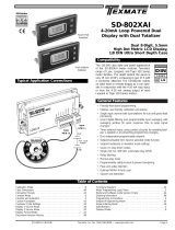
The figure below shows the locations of the different output options available.
The 2RE, 4RE, 4OP y 4OPP options are alternative and only one of them can be installed in the M1 connector.
The RS2 y RS4 options are also alternative and only one of them can be installed in the M2 connector.
The NMA or NMV are also alternative and only one of them can be installed in the M3 connector.
Up to three output options can be installed and operate simultaneously:
- 4-20mA or 0-10V (only one)
- RS232C or RS485 (only one)
- 2 RELAYS, 4 RELAYS or 4 OPTO (only one).
FRONT PANEL
COVER
ANALOGUE
OUTPUT
OPTION
(NMA/ NMV)
MAIN BOARD
RS232C/ RS485
OUTPUT
DISPLAY
RELAYS/ OPTO
OUTPUT
POWER FILTER
CIRCUIT
M3
CONNECTOR FOR
ANALOGUE OUTPUT
M1
CONNECTOR
RELAYS OUTPUT
M2
CONNECTOR FOR RS
OUTPUT
2.1 Dimensions and mounting
Front: 96 x 48 mm Depth: 60 mm
Panel cut-out: 92 x 45 mm
CLEANING: frontal cover should be cleaned only with a
soft cloth soaked in neutral soap product.
DO NOT USE SOLVENTS
8
The figure below shows the locations of the different output options available.
The 2RE, 4RE, 4OP y 4OPP options are alternative and only one of them can be installed in the M1 connector.
The RS2 y RS4 options are also alternative and only one of them can be installed in the M2 connector.
The NMA or NMV are also alternative and only one of them can be installed in the M3 connector.
Up to three output options can be installed and operate simultaneously:
- 4-20mA or 0-10V (only one)
- RS232C or RS485 (only one)
- 2 RELAYS, 4 RELAYS or 4 OPTO (only one). 2.1 Dimensions and mounting
Front: 96 x 48 mm Depth: 60 mm
Panel cut-out: 92 x 45 mm
CLEANING: frontal cover should be cleaned only with a
soft cloth soaked in neutral soap product.
DO NOT USE SOLVENTS

59
2.2 Programming guide
How to get into programming mode?
First, plug the instrument to the corresponding supply, automatically a display test will be done and after that the software
version will be shown then the instrument will go to work mode. Second, press the key to enter into the programming
mode, the indication "-Pro-" will appear on the display then.
How to store programmed parameters?
If we want to save the changes that we have done in the programming, we must complete the programming of all the
parameters contained in the routine we are in. In the last step of the routine, as a result of pressing on the key,
“StorE” will de displayed during a few seconds, meanwhile all the data are stored in memory. Then the instrument will go
back to working mode.
How is programming routine organised?
Programming software is composed by a number of menus and submenus hierarchically organized. On figure below,
beginning with indication "-Pro-", press repeatedly to get access to programming menus. Modules 3, 4 and 5 will only
be shown if the option for setpoints, analogue output or RS option has been plugged in. Selecting one menu, the access to
the different programming submenus is done by pressing .
-Pro- CnInP
Input
Selection
StorE
RUN
CndSP SEtP Anout rSout LoGIn
Display
Configuration
Setpoints
Configuration
Analogue
Output
Configuration
RS Output
Configuration
Logic
Functions
Module selection level

10
Accessing to programmed parameters
Thanks to the tree structure, the programming routines allow to access to one parameter and modify it without passing
through the whole list of parameters.
To advance through programming
The progress through the programming routines is done by pressing key.
In general, the steps to be done will be push key a certain number of times to select an option and push key to
validate the change and going forward to the next step of the program.
The numerical values are programmed digit by digit as explained in the next paragraph.
Programming numerical values
When the parameter is a numerical value, the first of the digits to be programmed will appear blinking on display.
The method of introducing a value is as follow:
Digit selecting: Press repeatedly the key to shift from left to right over all the display digits included the LED
direction indicators (when the programmed function requires it).
Changing the digit value: Press repeatedly the key to increase the value of blinking digit until it has the desired
value or to alternate the LED Up and Down arrows indicators (MAX and MIN).
Selecting an option from the list
When the parameter is an option to be chosen among different possibilities, the key allows you to browse through
the list of options until you find the desired parameter

2.1 - Alimentación y conectores
2.3
–
Power supply and connectors
CN1
1 2
1 2
WIRING and POWER SUPPLY RANGE
MICRA-D
85 V – 265 V AC 50/ 60 Hz or 100 – 300 V DC
MICRA-D6
22 – 53 V AC 50/ 60 Hz or 10,5 - 70 V DC
Borne 1: Phase
Borne 2: Neutral
NOTE: When DC power supply (direct) polarity
in connector CN1 is indistinct.
WARNING: If not installed and used in accordance with these
instructions, protection against hazards may be impaired.
In order to guarantee the electromagnetic compatibility, the following
guidelines should be kept in mind:
- Power supply wires may be routed separated from signal wires.
- Never run power and signal wires in the same conduit.
- Use shielded cable for signal wiring and connect the shield to the ground.
- The cables section should be >0.25 mm2
INSTALLATION
To meet the requirements of the directive EN61010-1, where the unit is
permanently connected to the mains supply, it is obligatory to install a circuit
breaking device easy reachable to the operator and clearly marked as the
disconnect device.
CONNECTORS
CN1 To perform wiring connections, strip the wire leaving from 7 and 10 mm
exposed to air and insert it in the proper terminal while pushing the fingertip
down to open the clip inside the connector as indicated in the figures.
Each terminal accepts cables of section between 0.08 mm² and 2.5 mm² (AWG
26 ÷ 14).
11
11
2.3 – Power supply and connectors
CN1
1 2
1 2
WIRING and POWER SUPPLY RANGE
MICRA-D
85 V – 265 V AC 50/ 60 Hz or 100 – 300 V DC
MICRA-D6
22 – 53 V AC 50/ 60 Hz or 10,5 - 70 V DC
Borne 1: Phase
Borne 2: Neutral
NOTE: When DC power supply (direct) polarity
in connector CN1 is indistinct.
WARNING: If not installed and used in accordance with these
instructions, protection against hazards may be impaired.
In order to guarantee the electromagnetic compatibility, the following
guidelines should be kept in mind:
- Power supply wires may be routed separated from signal wires.
- Never run power and signal wires in the same conduit.
- Use shielded cable for signal wiring and connect the shield to the ground.
- The cables section should be >0.25 mm2
INSTALLATION
To meet the requirements of the directive EN61010-1, where the unit is
permanently connected to the mains supply, it is obligatory to install a circuit
breaking device easy reachable to the operator and clearly marked as the
disconnect device.
CONNECTORS
CN1 To perform wiring connections, strip the wire leaving from 7 and 10 mm
exposed to air and insert it in the proper terminal while pushing the fingertip
down to open the clip inside the connector as indicated in the figures.
Each terminal accepts cables of section between 0.08 mm² and 2.5 mm² (AWG
26 ÷ 14).

12
ENTER
RESET
OFFSET
MAX/MIN
TOTAL
PROG
MIN
MAX
TARE 1
2
3
4
DATA
2.4 Functions keys and LED's description in programming mode and RUN mode
KEY Function in programming mode
DATA
ENTER
- to step forward in programming menu
- to validate programmed values
- to exit programming menu
MAX/ MIN
TOTAL
- to move blinking digit
RESET
OFFSET
- to increase blinking digit value
- Direct access to Setpoints value
LED’s Function in programming mode
TARE
MAX Indicates rotation sense (polarity)
MIN Indicates rotation sense (polarity)
PROG Indicates you are in programming mode
1- 2 - 3 - 4 Indicates the Setpoint that is being
programmed
KEY Function in RUN mode
DATA
ENTER
- to enter programming menu or to visualize
parameters if programming is locked
MAX/ MIN
TOTAL
1st stroke allows TOTALIZER visualization (if activated)
2nd stroke allows Max visualization ( only Tachometer)
3ª stroke allows Min visualization ( only Tachometer)
Following stroke: back to current value.
RESET
OFFSET
In Tachometer mode reset of MAX/ MIN/ TOTAL (if
present on display)
In Counter mode Reset / OFFSET (starts measuring)
LED’s Function in RUN mode
TARE Indicates that there is an offset value programmed
MAX Fixed indicates rotation sense or count polarity
Blinking indicates visualization of a Max value
MIN Fixed indicates rotation sense or count polarity
Blinking indicates visualization of a Min value
PROG Not active in run mode
1- 2 - 3 - 4 Indicates the activated Setpoint

13
2.5 – Input signal (CN2) Connection
Refer to connection recommendations on page 11
CN2
PIN 1 = No Connection
PIN 2 = (+) 18 V Excitation
PIN 3 = (+) 8,2 V Excitation Namur sensors
PIN 4 = ( - ) Common excitation / input
PIN 5 = Signal B input
PIN 6 = Signal A input
PIN 7 = No Connection
PIN 8 = High voltage input (300 Vac max.)
CN2
1 2 3 4 5 6 7 8
Instrument´s rear view
CN2
1 8
MAGNETIC PICKUP
Secondary
Principal
CN2
1 8
CONTACT CLOSURE
Secondary
Principal
1
CN2
8
NAMUR sensor
Secondary
Principal
CN2
1 8
ENCODER
EXC COMM OUTB OUTA
ENCODER
CN2
1 8
PNP/ NPN SENSOR
Exc Out Comm
Secondary
Exc Out Comm
Principal
CN2
1 8
10- 300 Vac
CN2
1 8
MAGNETIC PICKUP
Secondary
Principal
CN2
1 8
CONTACT CLOSURE
Secondary
Principal
1
CN2
8
NAMUR sensor
Secondary
Principal
CN2
1 8
ENCODER
EXC COMM OUTB OUTA
ENCODER
CN2
1 8
PNP/ NPN SENSOR
Exc Out Comm
Secondary
Exc Out Comm
Principal
CN2
1 8
10- 300 Vac

14
3. INPUT PROGRAMMING
3.1 Selection of sensor type
The diagram below shows first the configuration menu of the different sensors types, next step is then going to the run
mode selection.
When selecting Contact closure sensor type, anti rebound filter will activate automatically
Both input channels are programmed automatically for the same type of sensor input.
CnInP
- 1 - -2 - - 3 - -4 - -5 - - 6 - -7 -
MODE INPUT TYPE
1 10 to 300 V ac
2 Magnetic pickup
3 NAMUR sensor
4 PNP sensor
5 NPN sensor
6 TTL/ 24 V Encoder
7 Contact closure
14
3. INPUT PROGRAMMING
3.1 Selection of sensor type
The diagram below shows first the configuration menu of the different sensors types, next step is then going to the run
mode selection.
When selecting Contact closure sensor type, anti rebound filter will activate automatically
Both input channels are programmed automatically for the same type of sensor input.
CnInP
- 1 - -2 - -3 - -4 - -5 - - 6 - -7 -
MODE INPUT TYPE
1 10 to 300 V ac
2 Magnetic pickup
3 NAMUR sensor
4 PNP sensor
5 NPN sensor
6 TTL/ 24 V Encoder
7 Contact closure

15
MODE
COUNT CHRON FREC TAC
UP DOWN
In-A In A-B
PrO
PHASE
UP-DOWN
INDEP DIR
3.2 COUNTE
R
mode pro
g
rammin
g
dia
g
ram
15
MODE
COUNT CHRON FREC TAC
UP DOWN
In-A In A-B
PrO
PHASE
UP-DOWN
INDEP DIR
3.2 COUNTER mode programming diagram

16
3.3 Counter confi
g
uration
INPUTS
The counter has two inputs, the A input receives the
pulses to count, and the B input serves to inhibit the
count or to change the count direction, except in case of
bidirectional counter IndEP where the second input is
also used to count pulses.
PULSE MEASUREMENT
The pulses applied to the input are detected in the rising
edge and immediately update the value of the counter
and the setpoints status if the card is installed. The
display updates every 100 ms. In a power failure or
disconnection from the supply source, the instrument
keeps the count values.
VARIABLES
The main variable of the counter is the PROCESS
variable that is the number of pulses registered from the
last RESET operation.
If the totalizer option is enabled, we have PROC and
TOTAL variables.
The TOTAL variable counts the total number of pulses
received, independently of the reset operations that may
take place in the process display.
DISPLAY
Process: The limits of the display are 99999 and -
99999. When the instrument exceeds 99999, it shows
OVER, and when it falls below -99999, it shows UNDER.
The positive sign is indicated by the red LED Up arrow
located on the left side of the display and the negative
sign is indicated by the red LED Down arrow located on
the left side of the display.
The decimal point can be located in anyone of the digits
of the display, and it has not value, that is, the display
always shows the whole part of the measurement.
Total: The limits of the display are 99999999 and
-9999999. When the instrument exceeds these limits the
display shows the indications OVER or UNDER.
The negative sign, when the value has less than five
digits, appears in the most significant digit of the
display.
The negative sign is indicated by the MIN LED.
When the total value has more than five digits, the
display alternates the 4 digits high order part and the 4
digits low order part (the letters 'H' and 'L' in the
auxiliary digit indicate which part is on display.
The decimal point can be located in anyone of the digits
of the low part, and it does not have value, the display
shows the whole part of the measurement.

3.4. Mode count programming
The input setup is available on the 'CnInp' module which
allows configuration of the count mode and batch operation.
3.1.1. Count Modes
The software provides setup for five different count modes:
uP
Up count
do
Down count.
In-A
Allows count on A input regardless of input B
InA-B
Pulses applied at the A input are added or subtracted to the
count display if the B input is at low level and being used as
inhibited input.
uP-do IndEP
Pulses applied at the A input are added to the count display
while pulses at the B input are subtracted.
uP-do dIrEC
When B input is at low level, the pulses applied at the A
input increment the count. When B input is at high level, the
pulses at the A input decrement the count.
uP-do PHASE
The rising edges at the A input increment the count if the B
iinput is at low level. The falling edges at the A input
decrement the count if the B input is at low level.
Unidirectional counters:
MODE UP INA-B
A counts up if B is '0'. B inhibits count.
1
p
rocess
in
p
ut
A
in
p
ut B
23 45
MODE DO INA-B
A counts down if B is '0'. B inhibits count.
8
p
rocess
in
p
ut
A
in
p
ut B
76 54
17
17
3.4. Mode count programming
The input setup is available on the 'CnInp' module which
allows configuration of the count mode and batch operation.
3.1.1. Count Modes
The software provides setup for five different count modes:
uP
Up count
do
Down count.
In-A
Allows count on A input regardless of input B
InA-B
Pulses applied at the A input are added or subtracted to the
count display if the B input is at low level and being used as
inhibited input.
uP-do IndEP
Pulses applied at the A input are added to the count display
while pulses at the B input are subtracted.
uP-do dIrEC
When B input is at low level, the pulses applied at the A
input increment the count. When B input is at high level, the
pulses at the A input decrement the count.
uP-do PHASE
The rising edges at the A input increment the count if the B
iinput is at low level. The falling edges at the A input
decrement the count if the B input is at low level.
Unidirectional counters:
MODE UP INA-B
A counts up if B is '0'. B inhibits count.
1
p
rocess
in
p
ut
A
in
p
ut B
23 45
MODE DO INA-B
A counts down if B is '0'. B inhibits count.
8
p
rocess
in
p
ut
A
in
p
ut B
76 54

Bidirectional counters:
MODE UP-DO INDEP
A counts up. B counts down.
1
p
rocess
in
p
ut
A
in
p
ut B
0 -1 2 3
0 1 0 1
MODE UP-DO DIREC
A counts up if B is ‘0’ and counts down if B is ‘1’
1
p
rocess
in
p
ut
A
in
p
ut B
2 3 4 3
-1 20
MODE UP-DO PHASE
Rising edge of A counts up if B is ‘0’. Falling edge of A
counts down if B is ‘0’.
1
p
rocess
in
p
ut
A
in
p
ut B
2 3 1 2
10 2
CndSP
PrOC tOtAL
PrO
dCdiS
OFFSEt
dcFAC
FACdi
nO
dCtOt
dCFAC
YES
FACtO
Programming diagram of the
DISPLAY in MODE: COUNTER
18
18
Bidirectional counters:
MODE UP-DO INDEP
A counts up. B counts down.
1
p
rocess
in
p
ut
A
in
p
ut B
0 -1 2 3
0 1 0 1
MODE UP-DO DIREC
A counts up if B is ‘0’ and counts down if B is ‘1’
1
p
rocess
in
p
ut
A
in
p
ut B
2 3 4 3
-1 20
MODE UP-DO PHASE
Rising edge of A counts up if B is ‘0’. Falling edge of A
counts down if B is ‘0’.
1
p
rocess
in
p
ut
A
in
p
ut B
2 3 1 2
10 2
CndSP
PrOC tOtAL
PrO
dCdiS
OFFSEt
dcFAC
FACdi
nO
dCtOt
dCFAC
YES
FACtO
Programming diagram of the
DISPLAY in MODE: COUNTER

3.5. Scaling setup
3.5.1. Options of the Process Variable
In the menu ProC of the CndSP module can be found the
parameters related to the PROCESS variable measurement, -
Decimal Point, Offset, Multiplier Factor-
DECIMAL POINT
The decimal point indication helps to read the display in the
desired engineering units.
The decimal point has no real value, i.e. the digits to the right
of the decimal point are not actually decimals. To read values
with resolution to the desired decimal places is achieved by a
combination of decimal point and scaling factor.
For example, suppose a system that provides 100 pulses per 2
meters length of a material. To display length in meters and
centimeters, you should program a factor of 2 (1 pulse = 2
cms) and place the decimal point to the third digit.
OFFSET
OFFSET is the value that takes the counter in a reset event.
By default it is zero whatever is the configuration.
Configurable in the menu ProC
The OFFSET is applied to the PROCESS variable exclusively.
When the OFFSET is different from zero, the LED TARE will
remain active while in the run mode.
SCALE FACTOR
The scale factor is programmable from 0.00001 to 99999.
Individual decimal point location makes possible to
program any value within this range independently from
the main decimal point of the display.
Any number below 1 act like a divisor while a number
above 1 acts like a multiplier. (It is not possible to program
a factor=0).
19
3.5.2 Configuration of display brightness level
CndSP
Enter > 3 s.
BriGH
-HI- -Lo-
Pro
19
3.5. Scaling Setup
3.5.1. Options of the Process Variable
In the menu ProC of the CndSP module can be found the
parameters related to the PROCESS variable measurement, -
Decimal Point, Offset, Multiplier Factor-
DECIMAL POINT
The decimal point indication helps to read the display in the
desired engineering units.
The decimal point has no real value, i.e. the digits to the right
of the decimal point are not actually decimals. To read values
with resolution to the desired decimal places is achieved by a
combination of decimal point and scaling factor.
For example, suppose a system that provides 100 pulses per 2
meters length of a material. To display length in meters and
centimeters, you should program a factor of 2 (1 pulse = 2
cms) and place the decimal point to the third digit.
OFFSET
OFFSET is the value that takes the counter in a reset event.
By default it is zero whatever is the configuration.
Configurable in the menu ProC
The OFFSET is applied to the PROCESS variable exclusively.
When the OFFSET is different from zero, the LED TARE will
remain active while in the run mode.
SCALE FACTOR
The scale factor is programmable from 0.00001 to 99999.
Individual decimal point location makes possible to
program any value within this range independently from
the main decimal point of the display.
Any number below 1 act like a divisor while a number
above 1 acts like a multiplier. (It is not possible to program
a factor=0).
3.5.2 Configuration of display brightness level
CndSP
Enter > 3 s.
BriGH
-HI- -Lo-
Pro

DISPLAY FORMAT
When the total value is between -9999 and 99999, it is shown
on the display with the letter ‘L’ in the auxiliary digit and with
the red led up and down arrows for positive and negative.
(positive)
(negative)
When the accumulated value exceeds from four digits, the
display alternates a 4 digit high order part (with the letter 'H'
in the auxiliary digit) and a 4 digit low order part (indicated by
the letter 'L' in the auxiliary digit).
(The switching between high and low order parts takes place
at a rate of approximately 2s each part).
3.5.3. Totalizer Option
The totalizer facility can be enabled and disabled by
software.
The totalizer counter shares the same input setup, count
mode and count direction as the process counter but
provides separate decimal point and scaling factor.
Each pulse received at the input increment or decrement
the process and total counters exactly, although the
display value may vary from one to another according to
individual scaling factor and reset operations.
The limits of the display are -9999999 and 99999999
(7 digits with minus sign or 8 digits).
The decimal point can be set to five decimal places.
The scaling factor is programmable between 0.00001
and 99999 as for the process counter.
The totalizer has no possibility to load a user selected
display value in a reset event.
3.5.4. Totalizer visualisation
The total value accumulated since the last reset will be
displayed in the format indicated hereafter, when
pressing on key TOTAL (if activated).
20
20
DISPLAY FORMAT
When the total value is between -9999 and 99999, it is shown
on the display with the letter ‘L’ in the auxiliary digit and with
the red led up and down arrows for positive and negative.
(positive)
(negative)
When the accumulated value exceeds from four digits, the
display alternates a 4 digit high order part (with the letter 'H'
in the auxiliary digit) and a 4 digit low order part (indicated by
the letter 'L' in the auxiliary digit).
(The switching between high and low order parts takes place
at a rate of approximately 2s each part).
3.5.3. Totalizer Option
The totalizer facility can be enabled and disabled by
software.
The totalizer counter shares the same input setup, count
mode and count direction as the process counter but
provides separate decimal point and scaling factor.
Each pulse received at the input increment or decrement
the process and total counters exactly, although the
display value may vary from one to another according to
individual scaling factor and reset operations.
The limits of the display are -9999999 and 99999999
(7 digits with minus sign or 8 digits).
The decimal point can be set to five decimal places.
The scaling factor is programmable between 0.00001
and 99999 as for the process counter.
The totalizer has no possibility to load a user selected
display value in a reset event.
3.5.4. Totalizer visualisation
The total value accumulated since the last reset will be
displayed in the format indicated hereafter, when
pressing on key TOTAL (if activated).
/