Page is loading ...

51
Menu 23
-
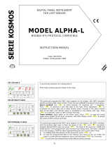
rAtE
-
. Select reading rate.
The reading r
ate determines the rate at which the display is updated. This parameter
affects the display, the setpoints, the analog output and the BCD output. Available
values are 16, 4 and 1 per second. Press
to select desired rate. Lower levels
produce slower displ
ay responses to signal changes. The 16 readings/s option will
update the display at the rythm of the signal conversion.
For temperature configurations the effective rate is half the selected number of
readings/s.
ENTER
Validate the choice and return to the "
-
Pro
-
" stage.
ESC
Cancel the programming and go to the "
-
Pro
-
" stage.
MULTIFUNCTION
DIGITAL PANEL INSTR
UMENT
MODEL BETA-M
MODBUS PROTOCOL COMPATIBLE
INSTRUCTIONS MANUAL
CODE: 30727004
EDITION: 18 May 2004
Valid
for instruments from s/n
212363
[51.1] Reading Rate
TARE
RESET
LIMIT
MAX/MIN
DATA
ESC
ENTER
M
A
X
M
I
N
HOLD
TARE
1
2
3
4

52
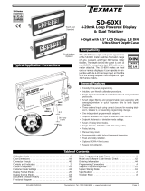
If the display reading is unstable due to small signal variations or noise, the use of digital filters may help to reduce these effects
and eliminate display
jittering. The filter
-
E parameter only appears for process, load cell or potentiometer inputs.
The figure 52.1 represents the access level to menu 25 -
FILt
-
. At this stage, you can
use one of the following keys:
ENTER
To enter the first step of the menu.
To skip this menu and pass to the menu 26
-
round.
ESC
To cancel this routine and return to the "
-
Pro
-
" stage.
Menu 24 FILt
-
P.
Set filter P level.
The P filter acts as a delay on the display response to signal variations produced at the
input. The effect of incrementing this filter level results in a softer response of the
display to the input variatio
ns. Select filter level from 0 (filter disabled) to 9 using the
key.
ENTER
Validate changes and advance to the next step.
ESC
Cancel this routine and return to the "
-
Pro
-
" stage.
Menu 24 FILt
-
E.
Set filter E level.
The E filter cuts off input variations exceeding from the limits of a moving band. This
band becomes more selective as the filter lev
el is increased. Select filter level from 0
(filter disabled) to 9 using the
key.
ENTER
Validate changes and advance to the next step.
ESC
Cancel this routine and return to the "
-
Pro
-
" stage.
Menu 25
-
DIGITAL FILTERS
[52.1] Access to the Me
nu
TARE
RESET
LIMIT
MAX/MIN
DATA
ESC
ENTER
M
A
X
M
I
N
HOLD
TARE
1
2
3
4
[52.2] Fil
ter
-
P Level
TARE
RESET
LIMIT
MAX/MIN
DATA
ESC
ENTER
M
A
X
M
I
N
HOLD
TARE
1
2
3
4
[52.3] Filter
-
E Level
TARE
RESET
LIMIT
MAX/MIN
DATA
ESC
ENTER
M
A
X
M
I
N
HOLD
TARE
1
2
3
4

53
3
Menu 24 AVErAG. Program nº of readings to average.
This value represents the number of readings that are summed up together and
averaged before the display is updated.
Use the
(change value) and
(change digit) keys to program
the desired
value from 1 to 200.
ENTER
Validate all changes in this menu and return to the
-
Pro
-
stage.
ESC
Exit this step and return to the
-
Pro
-
stage.
INTRODUCTION TO THE
KOSMOS SERIES
Th is ca ta logue does not con stit ute a form a l
agreement.
All information given in this m
anual is subject to
change without notice.
The KOSMOS SERIES brings a new phylosophy in digital
panel instrumentation which is expressed by multipurpose,
modular
-
concept devices providing a rich array of basic
functions and advanced capabilities.
With a
fully MODULAR DESIGN, it is possible to implement a
wide variety of applications by only adding the adequate
options.
Intelligence within allows the meter to recognize the options
installed and ask for the necessary parameters to properly
function within
desired margins. The basic instrument without
output options omits these data in the program routines.
The instrument's CALIBRATION is made at the factory
eliminating the need for adjustment potentiometers.
Any circuit or option that may need any adjust i
ncorporates a
memory where calibration parameters are stored, making it
possible the optional cards be totally interchangeable without
need of any subsequent adjust.
Custom CONFIGURATION for specific applications can be
made quickly and easily through five front panel keys,
following structured choice me
nus aided by display prompts
at each programming step.
Other features of the KOSMOS family include :
CONNECTIONS via plug
-
in terminal blocks without
screws and CLEMP
-
WAGO clips cable retention system.
DIMENSIONS
Models ALPHA & BETA 96x48x120 mm DIN 4
3700
Models MICRA & JR/JR20 96x48x60 mm DIN 43700
CASE MATERIAL UL
-
94 V0
-
rated polycarbonate.
PANEL INSTALLATION by means of single part fingertip
without screws.
To guarantee the meter's technical specifications, it is advised to
check its calibration at periodical intervals according to the ISO9001
standards for the particular application operating criteria. Calibration
should be perfomed at the factory or in a qualified laboratory.
[53.1] Average Filter
TARE
RESET
LIMIT
MAX/MIN
DATA
ESC
ENTER
M
A
X
M
I
N
HOLD
TARE
1
2
3
4

54
4
This menu allows selection among six levels of display rounding. When resolution is not critical, a rounding increment other than 1
may help stabilize the display.
The figure 54.1 shows the indication corresponding to th
e access to the round menu.
Press one of the following keys:
ENTER
To get access to this menu.
To skip this menu and pass to the menu 27
-
VoL.
ESC
To cancel this menu and return to the "
-
Pro
-
" stage.
Menu 26
-
round.
Select rounding increment.
Press repeatedly the
key to scroll through available options for the round filter
["
001
" = no rounding, "
005
" = round to 5 counts, "
010
" = round to 10 counts,
"020
" = round to 20 counts, "
050
" = round to 50 counts or "
100
" =
round to 100
counts].
ENTER
Validate changes and return to the "
-
Pro
-
" stage.
ESC
Exit this step and return to the "
-
Pro
-
" stage.
DIGITAL PANEL INSTRUMENT
BETA FAMILY
MODEL BETA-M
Men
u 25
-
ROUND
(process, load cell and potentiometer)
[54.1] Inicio
TARE
RESET
LIMIT
MAX/MIN
DATA
ESC
ENTER
M
A
X
M
I
N
HOLD
TARE
1
2
3
4
[54.2] Valor de redondeo
TARE
RESET
LIMIT
MAX/MIN
DATA
ESC
ENTER
M
A
X
M
I
N
HOLD
TARE
1
2
3
4
Index
1
-
Beta
-
M model overview
............................................................................................................................................
6
-
7
1.1
Mode RUN: front
-
panel description
........................................................................................................................
8
1.2
Mode PROG: front
-
panel description
......................................................................................................................
9
2
-
Getting started
............................................................................................................................................................
10
2.1
Power and connectors
................................................................................................................................
.
11
-
12
2.2
Programming instructions
............................................................................................................................
13
-
14
2.3
Programming guide
............................................................................................................................................
15
3
-
Programming module 10. Input co
nfiguration diagram
...........................................................................................
16
-
17
3.1
Program process input. Menu 11
..................................................................................................................
18
-
20
3.1.1
Connections (V, mA)
......................................................................................................................
21
-
22
3.2
Program load cell input. Menu 12
.................................................................................................................
23
-
24
3.2.1
Connections (mV/ V)
.............................................................................................................................
25
3.3
Program Pt100 input. Menu 13
....................................................................................................................
26
-
27
3.3.1
Connections
.........................................................................................................................................
28
3.4
Program thermocouple input. Menu 14
.........................................................................................................
29
-
31
3.4.1
Connections (J, K, T, R, S, E)
................................................................................................................
32
3.5
Program potentiometer input.
Menu 15
...............................................................................................................
33
3.5.1
Connections
.........................................................................................................................................
33

55
5
DIGITAL PANEL INSTRUMENT
BETA FAMILY
MODEL BETA-M
4
-
Programming module 20. Display configuration diagra
m
.........................................................................................
34
-
35
4.1
Scaling. Menus 21 and 22
............................................................................................................................
36
-
45
4.2
Integrator. Menu 23
....................................................................................................................................
46
-
48
4.3
Display options, Filters and Round
.......................................................................................................................
49
4.3.1
Display options. Menu 24
......................................................................................................................
50
-
51
4.3.2
Filters. Menu 25
..................................................................................................................................
52
-
53
4.3.3
Round. Menu 26
.........................................................................................................................................
54
4.4
Automatic volume calculation. Menu 27
........................................................................................................
55
-
58
5
-
Front
-
panel functions and
remote inputs
5.1
Front
-
panel functions
...................................................................................................................................
59
-
60
5.2
Remote inputs
....................................................................................................................................................
61
5.2.1
Table of remote input logic functions
....................................................................................................
62
-
64
5.2.2
Program remote input logic functions
..........................................................................................................
65
6
-
Programming parameters lockout
................................................................................................................................
.
66
6.1
Lockout routine
..................................................................................................................................................
67
7
-
Output options
.....................................................................................................................................................
68
-
69
8
-
Technical specifications
.........................................................................................................................................
70
-
71
8.1
Dimensions and mounting
...................................................................................................................................
72
9
-
Warranty
....................................................................................................................................................................
74
10
-
Declaration of conformity
.............................................................................................................................................
76
ANNEXES. Index
................................................................................................................................................................
78
4.4. Display Volume based on Pressure
There are several methods to calculate the volume of a fluid
in a tank.
If a pressure sensor is placed i
n the bottom of the tank, the
display may be scaled to convert the sensor's pressures into
liquid height.
The Beta
-
M provides different approaches to calculate liquid
volume.
1. For some special regular tank shapes, if you know the
mathematical relations
hip between pressure and volume, it
will only be necessary to scale the display by two points. For
example, for a cylindric vertical tank, volume is the product of
the cylinder base area and the liquid height.
2. If the tank is irregularly shaped, you can
use the
linearization feature to readout volume utilizando el método
teach y linealización por tramos.
The method consists of filling the tank with known amounts
of liquid, teach the input and enter the volume at each of the
selected points over the heigh
t of the tank. The more the
number of points used, the more accurate the measurement
will be.
3. A third method that offers the instrument to extract
volume is to set the automatic volume calculation function.
This function can be used when the tank's sha
pe correspond
to one of the figures represented at right.
Automatic Volume Calculation
The instrument has most common tank geometry functions
pre
-
programmed to calculate volume; spherical, horizontal
cylinder, horizontal cylinder with spherical ends and conical
b
ottom vertical cylinder. The user only has to enter the tank
dimensions as requested in the program routine.
D1
D1
D1
L1
L1
Typ 1
-
Sphere
Typ 2
-
Cylinder
Typ 3
-
Sphere+Cylinder
Typ 4
-
Silo
L2
L3
L1
D1
D2
D3
L2
L1
D1
D2
L1
D1
D2
L3
D3

56
6
ANALOG OUTPUT
OPTION
BCD PARALLEL
OUTPUT OPTION
MULTI
-
INPUT
CARD
A/D CONVE
RTER
CIRCUIT
RS232C/ RS485
OUTPUT OPTION
RELAY/ OPTO
OUTPUT OPTION
POWER FILTER
CIRCUIT
CASE WITH
FIXING CLIPS
MAIN CIRCUIT
FRONT
COVER
Programming Procedure to Readout Volume
When
using this method to display volume, a
pressure sensor must be placed at the bottom of the
tank to drive a signal proportional to fluid level.
The first scaling phase is to convert the input signal
to display height in meters. The height measurement
is s
ubsequently used to calculate volume.
The relation between pressure and height is linear,
so two scaling points are enough to define the scale.
The decimal point position must be chosen so that
the display values are expressed in meters, for
example, if t
he fluid level on top scale is 1.5m,
suitable programmings would be 0001.5, 001.50,
01.500 or 1.5000 depending on desired resolution.
Once the signal is scaled to measure level in meters,
the second phase is to activate the option VOL to
display volume
. This option is enabled by selecting
one of the available tank shapes (see figure). After
this, you must enter the diameter and length of the
tank in meters, and finally set the decimal point of
the display, which is independent from the decimal
point pro
grammed in the scaling procedure.
Volume is expressed in whole liters despite of the
point position.
-
VoL
-
27
no
SHAPE
27
tYP 1
SHAPE
27
tYP 2
SHAPE
27
tYP 3
SHAPE
27
tYP 4
SHAPE
27
02.000
dIAM
-
1
27
00000.
dIAM
-
1
27
02.000
dIAM
-
1
27
06.000
LEn
-
1
27
00000.
LEn
-
1
27
02.000
dIAM
-
1
27
06.000
LEn
-
1
27
00000.
LEn
-
1
27
02.000
dIAM
-
1
27
06.000
LEn
-
1
27
03.000
dIAM
-
2
27
00.000
LEn
-
2
27
03.000
dIAM
-
3
27
01.000
LEn
-
3
27
00000.
LEn
-
3
27
Programming Diagram
DISPLAY AND
KEYBOARD MODULE

57
7
This menu appears exclusively for process and potentiometer configurations.
I t is not possible to enable this option if the
integrator is active (menu 23).
The automatic volume calculation facility can be only used when the tank's shape is on
e of the
pre
-
programmed shapes shown in page 55.
The figure 57.1, shows the indication "27 -
VoL
-
" corresponding to the input stage of
the automatic volume calculation
menu.
Use one of the following keys:
ENTER
To get acces to this menu.
To pass to the Pasar al Submenú 21
-
SCAL.
ESC
To cancel the programming and return to the "
-
Pro
-
" stage.
Selection of the tank's shape. There are five options :
-
no
-
to disable this facility,
-tYP 1- for sphererical shape, -tYP 2- for horizontal cylinder, -tYP 3-
for horizontal
cylinder with end caps and
-t
YP 4
-
for conical bottom vertical cylinder (silo).
See figures in page 55.
Press
to choose the most appropriate shape from the list (or set the option
-
no
-
to disable volume calculation).
ENTER
Validate the choice and advance to the next programming phase.
ESC
Cancel this routine and return to the "
-
Pro
-
" stage.
After selecting the tank's shape, it is necessary to enter the dimensions of the t
ank.
Figure 57.3 shows the phase corresponding to the programming of the diameter D1.
Press repeatedly the
key to set the active digit to the desired value and
to move one digit to the right until the value for the diameter D1
, in meters is
completed on the display (the digits to the right of the decimal point are fractions of
meter).
ENTER
Validate the entry and advance to the next programming phase.
ESC
Cancel this routine and return to the "
-
Pro
-
" stage.
The BETA-
M model incorporates new technical and
functional characteristics including more filtering
options, software lockout, a variety of programmable
remote inputs and many other performance capabili-
ties that
provides an extraordinary flexibility to adapt
to a wide range of indication and control needs.
The BETA-
M model is a digital multifunction instrument
whose input stage admits, as selected by the user the
following configurable input types:
-
PROCESS (
V, mA)
-
LOAD CELL (mV/V)
-
Pt100 SENSOR
-
THERMOCOUPLE (J, K, T, R, S, E)
-
POTENTIOMETER
The input card allows direct connection to a wide variety of
transducers, transmitters or primary sensors without need for
changing any component or circuit. Th
e meter's configuration
for a particular input type is made entirely by software.
An optional 8-
digit totalizer/integrator accumulates time
dependent quantities using a timebase or either stores batch
readings.
Standard featur
es of the basic instrument include the reading
of the input variable plus a selectable second variable in the
lower display, max and min readings detection, remote hold,
tare operation and a full complement of programmable logic
functions.
Special softwar
e capabilities are program lock
-
out for
individual menus or the entire program parameters, as well
as the possibility to restore factory configuration at any time.
In addition, a variety of plug-
in output cards can be installed
at any time to meet furthe
r system requirements: analog or
digital control via 0-10V/ 4-
20mA or relay/ transistor outputs
and communication via serial RS232C/ RS485 or BCD parallel.
Each option has a separate programming module to configure
relating parameters, which is activated w
hen the card is
installed.
All output options are optoisolated from input signal and
power supply.
The basic instrument is a soldered assembly composed of the
main board, the display and keyboard module, the power
filtering circuit, the A/D converter circuit and the multi-
input
card (see page 6).
1. MODEL BETA
-
M
This instrument conforms with the following directives: 89/336/CEE and 73/23/CEE
Caution: Read complete instructions to ensure safety protections.
Menu 27
-
AUTOMATIC VOLUME
CALCULATION
[57.1] Access to the Menu
TARE
RESET
LIMIT
MAX/MIN
DATA
ESC
ENTER
M
A
X
M
I
N
HOLD
TARE
1
2
3
4
[57.2] Tank's Shape
TARE
RESET
LIMIT
MAX/MIN
DATA
ES
C
ENTER
M
A
X
M
I
N
HOLD
TARE
1
2
3
4
[57.3] Diameter 1
TARE
RESET
LIMIT
MAX/MIN
DATA
ESC
ENTER
M
A
X
M
I
N
HOLD
TARE
1
2
3
4

58
8
If you selected the spherical shape (tYP 1), this item does not appear. Please, go to
the phase represented by figure 58.2.
For the other shapes program the length L1 (see figures in page 55) by using
to increment digit value and
to move to next digit until completing the desired
value in meters (the decimal point notation marks the position of whole meters).
ENTER
Validate the entry and a
dvance to the next programming phase.
ESC
Cancel the programming and return to the "
-
Pro
-
" stage.
After programming the tank dimensions, the display goes to all zeros with the decimal
point in flash. This is the decimal point of t
he volume display, which is independent of
that programmed in the scaling routine.
Shift the decimal point to the desired position using
. If no decimal point is
required, locate it to the rightmost digit.
ENTER
Validate the entry and go to the "
-
Pro
-
" stag
e.
ESC
Cancel the programming and return to the "
-
Pro
-
" stage.
1.1
-
RUN MODE: FRONT
-
PANEL FUNCTIONS
LED HOLD
LED TARE
TARE
RESET
LIMIT
MAX/MIN
DATA
ESC
ENTER
M
A
X
M
I
N
HOLD
TARE
1
2
3
4
[58.1] Length 1
TARE
RESET
LIMIT
MAX/MIN
DATA
ESC
ENTER
M
A
X
M
I
N
HOLD
TARE
1
2
3
4
[58.2] Decimal Point
TARE
RESET
LIMIT
MAX/MIN
DATA
ES
C
ENTER
M
A
X
M
I
N
HOLD
TARE
1
2
3
4
SILO
: The silo shape (tYP 4) is a combination of three parts and requires three diameters and thr
ee lengths to be
programmed. You may have a tank that is composed of only one or two of the parts in which this shape is divided, according
to figures on page 55. To overcame this situation, the length of the missing parts should be programmed to zero.
The
last phase of this routine is to set the decimal point of the display, go to figure 58.2.
TARE KEY
RESET KEY
LIMIT KEY
MAIN DISPLAY
KEYBOARD IN RUN MODE
LABEL
MAX/MIN KEY
DATA KEY
AUXILIARY DISPLAY
LED MIN
LED MAX

59
9
1.2
-
PROG MODE: FRONT
-
PANEL FUNCTIONS
TARE
RESET
LIMIT
MAX/MIN
DATA
ESC
ENTER
M
A
X
M
I
N
HOLD
TARE
1
2
3
4
TARE key
A push of the TARE key causes the current display to be
stored in the tare memory .
The TARE LED denotes that a tare value other than zero is
contained in the memory. The tare value (or offset for a
temperature m
eter) can be displayed on the second display
by pressing the
MAX/MIN
key.
To clear the tare memory, press and hold the RESET
key,
then press
TARE
. Release first
TARE
, then
RESET
.
If a tare or tare reset operation is impossible from the front-
panel, check the tare key lock settings (see page 67).
5.1
-
Front
-
panel functions
The meter provides the following function keys: TARE, RESET, LIMIT and MAX/MIN. The functionality of each one in the
"RUN" mode is described below.
LIMIT key
During the RUN mode, this key is only operative in case that
one of the following output options is installed : 2 relays (ref.
2RE), 4 relays (ref. 4RE), 4 NPN transistors (ref. 4OP) or 4
PNP transist
ors (ref. 4OPP).
The setpoint programmed values appear on the second
display at each push of the
LIMIT key independently of
whether they are enabled or inhibited. The auxiliary display
shows L1, L2, L3 or L4 depending of which value is being
read.
During the setpoints routine, the functionnality of the rest of
the keys remains active.
5. FRONT
-
PANEL AND LOGIC INPUT FUNCTIONS
TARE
RESET
LIMIT
MAX/MIN
DATA
ESC
ENTER
M
A
X
M
I
N
HOLD
TARE
1
2
3
4
TARE
RESET
LIMIT
MAX/MIN
DATA
ESC
ENTER
M
A
X
M
I
N
HOLD
TARE
1
2
3
4
ESC KEY
KEY
SECOND DISPLAY
MAIN DISPLAY
KEYBOARD IN PROG MODE
LABEL
KEY
ENTER KEY
AUXILIARY DISPLAY

60
10
Packing contents
Instructions manual in English, including Declaration of
Conformity.
Digital panel meter model Beta-
M.
Accessories for panel mounting (sealing gasket and fixing
clips).
Accessories for wiring connections (plug-in terminal blo
ck
connectors with a fingertip key).
Wiring label sticked to the plastic case
Set of labels with engineering units
Check the packing is complete.
Configuration
Power supply (pages 11 & 12)
The instruments with 115/230V AC power supply, are set
by defau
lt for a supply voltage of 230V (USA market 115 V
AC).
The instruments with 24/48V AC power supply, are set by
default for a supply voltage of 24V.
Check wiring label before applying power to the
instrument.
2. GETT
ING STARTED
Programming instructions (pages 13, 14 & 15)
The software is divided into several independently
accessible modules for configuration of
the input, the
display, the setpoint outputs, the analog output, the
communication output and the logic inputs.
Read carefully this section.
Input types (pages 16 & 17)
Verify input configuration before connecting the input
signal.
Programming paramet
ers lockout (page 54)
The instrument is shipped from the factory with all
programming levels accessible to the operator.
Software allows selective lockouts of the programming
parameters.
Lockout is recommended after programming the
instrument.
MAX/MIN key
Recalls the following parameters to the second display : first
push recalls peak, second push recalls valley, third push
recalls tare (or offset). If the integrator optio
n is enabled, the
fourth push recalls total and, if not enabled but the logic
function nº30 (totalizer+batch) is programmed to one of the
user inputs a new push shows the number of batch
operations. The last push after this sequence blanks the
lower displa
ys.
The auxiliary display indicates which variable is being read in
the second display : "HI" = peak, "Lo" = valley, "tA" = tare,
"oF" = offset, "bA" = nº of batches. The total value needs all
8 digits to be displayed.
Any selected paramete
r is permanently displayed and
continuously updated if no action is taken.
TO RE
SET PEAK, VALLEY, TOTAL or BATCH :
RESET key
Press
MAX/MIN
until desired parameter appears on the second
display. This parameter may be peak ('HI'), valley ('Lo'),
total (auxiliary digits blank or hi part of the total reading) or
number of
batch operations ('bA').
When desired variable is being read on the lower displays,
hold the
RESET
key and press
MAX/MIN
. Release first
MAX/MIN
,
then
RESET
.
A tare or tare reset ope
ration updates automatically the peak
and valley readings to the current display value.
ENTER key
A momentary push of the ENTER key gives access to the
programming mode.
ENTER key (3s)
Gives access to the program lock
-
out routine. Hold ENTER
for approx
imately 3s, at the end of which the meter prompts
the indication '
- - - -
' to enter the security code.
RESET + ENTER (3s)
A press of 3s of both RESET and ENTER restores the factory
settings to the memory of the instrument.
Press RESET first, then ENTER a
nd hold both until the
indication "StorE" appears on the second display.
TARE
RESET
LIMIT
MAX/MIN
DATA
ESC
ENTER
M
A
X
M
I
N
HOLD
TARE
1
2
3
4
TARE
RESET
LIMIT
MAX/MIN
DATA
ESC
ENTER
M
A
X
M
I
N
HOLD
TARE
1
2
3
4

61
11
2.1
-
Power supply and connector
To access hardware configuration, remove the meter from the
case as shown in figure 11.1.
115/230 V AC:
The instruments with 115/230 V AC power are
shipped from the factory for 230V AC (USA market 115V AC),
see figure 11.2. To change supply voltage to 115V AC, set
jumpers as indicated in table 11.1. The wiring label should be
modified to match new setup.
24/ 48 V AC: The instruments with 24/48V AC pow
er supply
are shipped from the factory for 24V AC, see figure 11.2. To
change supply voltage to 48V AC, set jumpers as indicated in
table 11.1. The wiring label should be modified to match new
setup.
Fig. 11.2.
Jumper location for 230 V or 48 V AC
Fig. 11.3.
Jumper location
for 115 V or 24 V AC
Table 1. Jumper settings.
Pin
1 2 3 4 5
230V AC
-
115V AC
-
48V AC
-
24V AC
-
Fig. 11.1. Disassembling
Factory Configuration
As shipped from the factory, the CN2 connector allows the
TARE, MAX/MIN and RESET operations be made in the same
way as from the front-panel keyboard and incorporates one
more function: the display HOLD.
If the user programs a '0' (no function) to all input pins, they
a
re automatically set to the default configuration.
CN2 : FACTORY DEFAULT CONFIGURATION
PIN (INPUT)
Function
Number
PIN 1 (INP
-
1)
RESET
Function nº 7
PIN 2 (INP
-
2)
HOLD
Function nº 9
PIN 3
COMMON
PIN 4 (INP
-
4)
TARE
Function nº 1
PIN 5 (INP
-
5)
PEAK/V
ALLEY
Function nº 6
The external electronics (fig.61.2) applied to the CN2
connector must be capable of withstanding 40 V and 20 mA
present at all terminals with respect to COMMON. In order to
guarrantee the electromagnetic compatibility, please refer to
the instructions given on page 12.
5.2
-
Logic Functions
The rear connector CN2 provides 4 user programmable opto
-
coupled inputs that can
be operated from external contacts or
logic levels supplied by an electronic system. Four different functions may be added to the functions available from the front
-
panel keys. Each function is associated to one of the CN2 connector pins (PIN 1, PIN 2, PI
N 4 and PIN 5) and is activated by
applying a falling edge or a low level pulse to the corresponding pin with respect to common (PIN 3).
Each pin can be assigned one of the 36 functions listed on the following pages.
Fig.61.1
CN2 LOGIC
3 2 1 J1
6 5 4 J2
CN2 type of input
PNP
J1 (2
-
3) J2 (5
-
6)
NPN
J1 (1
-
2) J2 (4
-
5)
Fig.61.2. Examples
of PNP, NPN and
contact
switch wiring.

62
12
5.2.1
-
Table of programmable functions
Definition of the c
olumn "Action"
Edge : The function is active when a negative edge is applied to the corresponding pin referred to common.
Level : The function is active as long as the corresponding pin is held at a low level with respect to common.
(*) Factory configurat
ion.
Nº
Name
Function
Action
0
NO
None
-
1
TARE (*)
Adds the curren
t display value to the tare memory
Edge
2
RESET TARE
Clears the tare memory
Edge
3
PEAK
Recalls the peak value
Level
4
VALLEY
Recalls the valley value
Level
5
RESET PEAK/VALLEY
Resets peak and valley readings
Edge
6
VISUAL (*)
Recalls various parameters to the second display; Peak, Valley, Tare or Offset
and, if they are active, the Totalizer and the Batch counters. The last action
blanks the second display.
Edge
7
RESET (*)
In combination with function (1) clears the tare memory.
In combination with function (6) clears the peak or valley memories, or the
totalizer or the batch counter
Edge
8
HOLD1
Holds the display
Level
9
HOLD2 (*)
Holds the display and the analog and BCD outputs
Level
0 to 9 : DISPLAY AND MEMORY FUNCTIONS
10 to 12 : FUNCTIONS ASSOCIATED WITH THE MEASUREMENT DISPLAY
Nº
Name
Function
Action
10
INPUT
Displays the signal input value in V or mA or mV
Level
11
GROSS
Displays the gross value (measureme
nt value + tare substracted)
Level
12
TARE
Displays the value of the tare memory
Level
CONNECTORS
To perform wiring connections, remove
the terminal block from the meter's connector,
strip the wire leaving from 7 to 10 mm exposed
and insert it into the proper terminal while pushing
the fingertip down to open the clip inside the
c
onnector as indicated in the figure.
Proceed in the same manner with all pins and plug the terminal block
into the corresponding meter's connector.
Each terminal accept cables of section between 0.08 mm² and 2.5 mm²
(AWG 26 ÷ 14).
The blocks provide remov
able adaptors into each terminal to allow
proper fastening for cable sections of <0.5 mm².
POWER CONNECTION
-
CN1
PIN 1
-
AC PHASE
PIN 2
-
GND (GROUND)
PIN 3
-
A
C NEUTRAL
INSTALLATION
To meet the requirements of the directive
EN61010
-
1, where the unit
is permanently connected to the mains supply it is obligatory to install
a circuit breaking device easy reachable to the operator and clearly
marked as the disconnect device.
WARNING
In order to guarantee electromagnetic compatibi
lity, the following
guidelines for cable wiring must be followed:
-
Power supply wires must be routed separated from signal wires.
Never
run power and signal wires in the same conduit.
-
Use shielded cable for signal wiring and connect the shield to
ground of
the indicator (pin2 CN1).
-
The cable section must be
0.25 mm2
I f not installed and used according to these instructions,
protection against hazards may be impaired.

63
13
Nº
Name
Function
Action
13
ANA GROSS
The analog output follows the gross value (measured value + tare).
Level
14
ANA ZERO
Puts the analog output to the zero state (0V or 4mA)
Level
15
ANA PEAK
The analog output follows the peak value
Level
16
ANA VALLEY
The analog output follows the valley value
Level
13 to 16 : FUNCTIONS ASSOCIATED TO THE ANALOG OUTPUT
17 to 23 : PRINT FUNCTIONS TO USE WITH RS232C or RS485 OUTPUTS
Nº
Name
Function
Action
17
PRINT NET
Prints the net value
Edge
18
PRINT GROSS
Prints the gross value
Edge
19
PRINT TARE
Prints the value of the tare
Ed
ge
20
PRINT SET1
Prints the value and the state of the setpoint 1
Edge
21
PRINT SET2
Prints the value and the state of the setpoint 2
Edge
22
PRINT SET3
Prints the value and the state of the setpoint 3
Edge
23
PRINT SET4
Prints the value and the state
of the setpoint 4
Edge
24 to 25 : FUNCTIONS ASSOCIATED WITH THE SETPOINT OUTPUTS
Nº
Name
Function
Action
24
FALSE SETPOINTS
Allows programming and operation of four setpoints without setpoint card
installed
Level
25
RESET SETPOINTS
Un
locks the setpoint latched outputs
Edge
26 to 36 : SPECIAL FUNCTIONS
Nº
Name
Function
Action
26
ROUND RS
Makes the serial output transmit the internal display value, without filters nor
rounding
Level
27
ROUND BCD
Make
s the BCD output drive out the display value without rounding
Level
2.2
-
Programming Instructions
Access to the programming mode
When power is applied to the instrument, the display briefly illuminates all
segments and LED's then shows the software version and finally enters in the
normal mode. Press ENTER
to enter in the programming mode. The second display
shows the indication "
-
Pro
-
" (fig. 13.1).
Exit from the program
ming mode without saving data
From any step of the program routines, a push of
ESC
returns the meter to the
-
Pro
-
stage. From this point, a new push of
ESC
shows momentarily the indication "qUIt" on the secon
d display,
the meter exits from the programming mode, restores the
previous configuration and returns to the normal operation. Any parameter change made before exiting in this mode is discarded.
Save changes in the configuration
In the programming mode, t
he instrument returns to the
-
Pro
-
stage at the end of each program menu. The data changes are not
saved at this point, to keep changes in the configuration parameters press
ENTER
, the second display shows momentarily the
indication "
StorE" while the new configuration is saved in the memory. After the instrument returns to the run mode.
Guidelines on programming instructions
The programming software is divided into 6 modules. Each module is organized in several independently accessibl
e menus and
each menu contains a list of parameters necessary to configure a specific function of the meter.
From the
-
Pro
-
stage, press repeatedly
to cycle around the existing modules : module 10 = Input configuration, module 20
= display configuration,
module 30 (if option is installed) = setpoints, module 40 (if option is installed) = analog output, module
50 (if option is installed) = serial outputs and module 60 = logic functions. Press
ENTER
to get access to the selected module
.
TARE
RESET
LIMIT
MAX/MIN
DATA
ESC
ENTER
M
A
X
M
I
N
HOLD
TARE
1
2
3
4
Fig. 13.1. PROG mode first step (
-
Pro
-
stage)
quit
quit
quit
quit
quit
quit
quit
Store
menu 11
menu 21
menu 31
menu 41
menu 51
menu 61
TARE
RESET
L
I
M
I
T
M
A
X
/
M
I
N
DATA
ESC
ENTER
M
A
X
M
I
N
HOLD
TARE
1
2
3
4
TARE
RESET
L
I
M
I
T
M
A
X
/
M
I
N
DATA
ESC
ENTER
M
A
X
M
I
N
HOLD
TARE
1
2
3
4
TARE
RESET
L
I
M
I
T
M
A
X
/
M
I
N
DATA
ESC
ENTER
M
A
X
M
I
N
HOLD
T
A
R
E
1
2
3
4
TARE
RESET
L
I
M
I
T
M
A
X
/
M
I
N
DATA
ESC
ENTER
M
A
X
M
I
N
HOLD
T
A
R
E
1
2
3
4
TARE
RESET
L
I
M
I
T
M
A
X
/
M
I
N
DATA
ESC
ENTER
M
A
X
M
I
N
HOLD
T
A
R
E
1
2
3
4
TARE
RESET
L
I
M
I
T
M
A
X
/
M
I
N
DATA
ESC
ENTER
M
A
X
M
I
N
HOLD
T
A
R
E
1
2
3
4
TARE
RESET
L
I
M
I
T
M
A
X
/
M
I
N
DATA
ESC
ENTER
M
A
X
M
I
N
HOLD
TARE
1
2
3
4

64
14
26 to 36 : SPECIAL FUNCTIONS (cont.)
Nº
Name
Function
Action
28
ASCII
Envío de los cuatro últi
mos dígitos de display a un indicador Micra
-S
Edge
29
SETS INHIBIT
Suspends setpoint operations and keeps the outputs to their OFF state
Level
30
BATCH
Adds the current display value to the totalizer and increments the batch
counter in one unit.
If the i
ntegrator is enabled (menu 23), this function does not work
Edge
31
VIEW TOTAL
Calls the totalizer value to the second display
Level
32
VIEW BATCH
Calls the batch counter to the second display
Level
33
RESET
TOTAL+BATCH
Resets the totalizer and the batc
h counter
Edge
34
STOP TOTAL
Inhibits the integrator operation
Level
35
PRINT
TOTAL+BATCH
Prints out the totalizer value and the batch counter value. If the integrator is
enabled, only the totalizer value is printed.
Edge
36
PRINT PEAK
Hold and print ma
x reading.
When this function is programmed the peak value detection is stopped. In the
activation edge, the peak register is cleared from the memory and the unit
starts reading new peak values. In the deactivation edge, the peak value
registered during the time the function was active is printed out through the
serial output
Level
In the step-
by
-step instructions, you are given the acti
on of the three buttons mainly
used to program data. The normal procedure at each step is to push on
a
number of times to make changes and push on
ENTER
to validate changes and
advance to the next programming step. At the end of a complete menu sequence the
meter returns to the
-
Pro
-
stage, where :
ENTER
to save changes and exit
ESC
to discard changes and exit
to select among available options
[page nº/figure nº] Mnemo
The auxiliary display
shows the
indentification of the
current menu.
The second display
shows the parameter
being programmed.
The programming instructions are composed by a general description and a series of step-
by
-
step instructions to be followed
sequentially. Each menu step is represented by an illustration of the display and keyboard module with indications (displays and
LED's), reference [page number . figure number] and a text describi
ng the action of each key at current step.
TARE
RESET
LIMIT
MAX/MIN
DATA
ESC
ENTER
M
A
X
M
I
N
HOLD
TARE
1
2
3
4
With respect to the figures in the step-
by
-
step instructions, the display
indications may have the following meanings :
1./ The first display
shows one of the available options with filled
-
out segments. That means that the display shows the choice made
previously. The use of
allows to select from available options.
2./ A series of black "8" also represents the display indication of a
previ
ous choice, with the difference that it cannot be changed in the
current step. If it is already the desired parameter, you may exit from the
menu by a push of ESC
without making changes or, if wanted to modify
it, a push of
ENTER
advanc
es the meter to the next step where changes
are allowed.
3./ A series of white "8" represents any numerical value that is
programmed by the
and
buttons.

65
15
Menu 61 Inp
-
1. Assign logi
c function to PIN 1.
The main display shows the function number assigned to logic input 1. Refer to the
table to select function and use the
key to change the number if desired.
Pass to the programming of the following logic input.
ENTER
Validate changes and return to the
-
Pro
-
stage.
ESC
Exit from this menu and go to the
-
Pro
-
stage.
Process indicator:
1.
Input programming, pages. 16
-
20
(M
).
2.
Signal wiring, pages. 21
-
22 (
M
).
3.
Scaling, pages. 34
-
45 (
M
).
4.
Configure the integrator option, pages 46
-
48 (
op
)
5.
Program remote inputs, pages. 61
-
65 (
R
).
6.
Install and configure output options, refer to respective
manual (
op
).
7.
Lockout programming,
pages. 66
-
67 (
R
).
Load cell indicator:
1.
Input programming, pages. 16, 23 and 24 (
M
).
2.
Signal wiring, page. 25 (
M
).
3.
Configure the display, pages. 50
-
54 (
M
).
4.
Program remote inputs, pages. 61
-
65 (
R
).
5.
Install and configure output options, refer to respec
tive
manual (
op
).
6.
Lockout programming, pages. 66
-
67 (
R
).
Pt100 thermometer:
1.
Input programming, pages. 17, 26 and 27 (
M
).
2.
Signal wiring, page. 28 (
M
).
3.
Program display options, pp. 34 -
35 and 42
-
45 (
R
).
4.
Program remote inputs, pages. 61
-
65 (
R
).
5.
Ins
tall and configure output options, refer to respective
manual (
op
).
6.
Lockout programming, pages. 66
-
67 (
R
).
Thermocouple meter:
1.
Input programming, pages. 17 and 29
-
31 (
M
).
2.
Signal wiring, page. 32 (
M
).
3.
Program display options, pp. 34 -
35 and 42
-
45 (
R
).
4.
Program remote inputs, pages. 61
-
65 (
R
).
5.
Install and configure ou
tput options, refer to respective
manual (
op
).
6.
Lockout programming, pages. 66
-
67 (
R
).
Potentiometer indicator:
1.
Input programming, pages. 17 and 33 (
M
).
2.
Set excitation jumper, page. 18 (
M
).
3.
Signal wiring, page. 33 (
M
).
4.
Scaling, pages. 34
-
45 (
M
).
5.
Config
ure the integrator option, pages 46
-
48 (
op
)
6.
Program remote inputs, pages. 61
-
65 (
R
).
7.
Install and configure output options, refer to respective
manual (
op
).
8.
Lockout programming, pages. 66
-
67 (
R
).
2.3
-
Programming guide
The steps listed here below should be followed to properly configure the indicator according to desired input. Steps are
marked depending on whether they are mandatory (
M
), recommended (
R
) or optional (
op
).
Menu 61
-
Program Logic Input 1
[65.2] Logic input PIN 1
5.2.2
-
Pr
ogram the logic functions
Press
ENTER
to enter in the programming mode (-
Pro
-
level) and press repeatedly
until the indication shown in figure 53.1 appears on the display. From this
stage press
ENTER
to acceed
the logic inputs configuration. The
key rotates
around the four logic inputs to view the function number assigned to each pin.
The
key changes the number if desired.
To program the logic inputs follow the procedure described below for input 1.
TARE
RESET
LIMIT
MAX/MIN
DATA
ESC
ENTER
M
A
X
M
I
N
HOLD
TARE
1
2
3
4
Fig. 53.1: Logic inputs
configuration module
TARE
RESET
LIMIT
MAX/MIN
DATA
ESC
ENTER
M
A
X
M
I
N
HOLD
TARE
1
2
3
4

66
16
Menu 12
Load cell:
a)
Input range [300mV, 60mV, 30mV, 15mV].
3. INPUT CONFIGURATION
Menu 11
Process
:
a)
Input type [VoLt= volts, AMP= milliamperes].
b)
Input range [1V, 10V] or [1mA, 20mA].
Excitation [24V, 10V].
- P r o C -1 1
C n F I n P1 0
- I n P u t -1 1
V o L t
- I n P u t -1 1
A M P
r A n G E1 1
1 - V
r A n G E1 1
1 0 - V
- L o A d -1 2
r A n G E1 2
3 0 0 - mV
r A n G E1 2
6 0 - mV
r A n G E1 2
3 0 - mV
r A n G E1 2
1 5 - mV
- P r o -
S u P P L Y
1 1
2 4 - V
S u P P L Y
1 1
1 0 - V
r A n G E1 1
1 - m A
r A n G E1 1
2 0 - m A
- P r o -
The instrument is supplied with all software
programming
parameters accessible to operator's modifications. After
completing the software configuration, it is recommended to
take the following steps:
1.
Lockout programming parameters to prevent from
accidental or unauthorized modifications.
2.
Lockout th
e tare key operation.
3.
The lockout can be applied to everything or to specific
menus or parameters. If some parameters should be
reprogrammed frequently, make a partial lock leaving
such parameters accessible. If no subsequent adjust
must be made, make a t
otal lock.
4.
The access to the lockout routine is allowed by entering
a safety code. At fabrication this code is set to 0000. We
recommend to change this code and to write it down and
keep safe.
5.
Prior to configure the meter, it is recommended to
organize a
ll data and keep a record s manual.
6. PARAMETER LOCKOUTS
TOTAL LOCKOUT
The access to the programming routines to read data is
allowed even if all parameters are locked out, but
it won t
be possible to enter or modify data
. In this case, when
entering in the programming mode, the second display shows
the indication
-
dAtA
-
instead of
-
Pro
-
.
SELECTIVE LOCKOUT
When only some parameters are locked out, all configuration
data can be read but
only non-
protected parameters can
be modified
. In such case, when entering in the
programming mode, the second display shows the indication
-
Pro
-
.
Selective lock
-
outs include the following groups:
Setpoint 1 configuration (menu 31).
Setpoint 2 configuration (menu 32).
Setpoint 3 configur
ation (menu 33).
Setpoint 4 configuration (menu 34).
Input configuration (module 10).
Scaling (menus 21/22, 23 and 27).
Display options and filtering (menus 24, 25 and 26).
Analog output configuration (module 40).
Serial output configuration (module 50).
L
ogic inputs configuration (module 60).
Direct access to the programming of the setpoint values
Those that refer to optional outputs only appear if the
corresponding option is installed.

67
17
Menu 15
Potentiometer
None.
Menu 13
Pt100 thermometer:
a)
Display units [ ºC, ºF ].
b)
Resolution [ 0.1º, 1º ].
c)
Offset [
-
9.9° to +9.9°,
-
99° to + 99°].
Menu 14
Thermocouple thermometer:
a)
Thermocouple type [ J, K, T, R, S, E ].
b)
Display units [ ºC
, ºF ].
c)
Resolution [ 0.1º, 1º ].
d)
Offset [
-
9.9° to +9.9°,
-
99° to +99°].
MODULE 10
-
INPUT CONFIGURATION ("CnFInP")
The figure shows the complete input configuration module which is divided into five menus. Each menu corresponds to a specific
configuration of the meter. You may only need to program the parameters of the desired configu
ration (process, load cell,
thermocouple, Pt100 or potentiometer).
- P o t -1 5
- P t 1 0 01 3
-
o
C -
- P t 1 0 01 3
-
o
F -
- P t 1 0 01 3
0. 1
o
- P t 1 0 01 3
1
o
- P t 1 0 01 3
o F F S E t1 3
0 0.0
- P r o -
- t C -1 4
-
o
C -
- t C -1 4
-
o
F -
- t C -1 4
0. 1
o
- t C -1 4
1
o
- t C -1 4
o F F S E t
1 4
0 0.0
- P r o -
- t C -1 4
t Y P E - J
- t C -1 4
t Y P E - K
- t C -1 4
t Y P E - t
- t C -1 4
t Y P E - r
- t C -1 4
t Y P E - S
- t C -1 4
t Y P E - E
- P r o -
6.1
-
Lockout programming routine
The lock
-
out programming routine is entered by depressing
the
ENTER key for 3 seconds and
introducing a security code.
This gives access to either the parameter list or to change the
code if desired.
If the user opts for changing the code, the unit asks for the
new one and returns to the normal operation. The old code is
replaced with the user
selected one, that will be asked next
time this routine is entered.
When the user enters the parameter list, each parameter is
indicated in the second display, while in the first one a
blinking digit allows setting a 1 to lock this item, or a 0 to
f
ree it.
There are two ways to lock
-
out the program; One is to lock
everything, which is accomplished by setting a 1 in the tot-
LC parameter (the remaining parameters are skipped except
the tare key lock).
The second is to individually lock some parts
of the program
menus leaving free those parts which are more liable to have
changes during normal operation.
88888
3s?
-
-
-
-
CodE
-
YES
-
CHAnGE
-
no
-
CHAnGE
0
tot
-
LC
tot
-
LC?
0
tArE
0
SEt1
0
SEt2
0
SEt3
0
SEt4
0
InPut
0
SCAL
0
FILt
0
AnAout
0
rs coM
0
LoGInP
0
SP VAL
-
-
-
-
CodE
code OK
1
0
yes
no
yes

68
18
Output options with instructions
manual edited before
December 1999, work properly with new versions of
Beta
-
M but some new features may not be described in
the options manual.
I f you are using an older output card connected to a
new Beta-
M and you want to take benefit of the new
function
s (see page 60), please call for an updated
edition of the options manual.
Optionally, model BETA-
M can incorporate one or several
output options for communications or control including :
COMMUNICATION
RS2
Serial RS232C
RS4
Serial RS485
BCD
BCD 24V/TT
L
CONTROL
ANA
Analogue 4
-
20 mA, 0
-
10 V
2RE
2 SPDT relays 8 A
4RE
4 SPST relays 0.2 A
4OP
4 open
-
collector NPN outputs
4OPP
4 open
-
collector PNP outputs
All options are optoisolated with respect to the input signal.
The options are supplied with a specific instr
uctions manual
describing characteristics, installation, connections and pro-
gramming. The output cards are easily installed on the meter's
main board by means of plug-
in connectors and each one
activates its own programming module that provides complete
s
oftware
-
configuration.
Additional capabilities of the unit with output options :
Control and processing of limit values via ON/OFF logic
outputs (2 relays, 4 relays, 4 NPN outputs or 4 PNP
outputs) or proportional output (4
-
20 mA or 0
-
10 V).
Communicatio
n, data transmission and remote programm-
ing via serial interface.
For more detailed information on characteristics, applications,
mounting and programming, please refer to the specific
manual supplied with each option.
7. OUTPUT OPTIONS
To have access to the input configuration module, press
ENTER
to pass from the run mode to the programming mode
and press
to make the lower displays show the
indication "10 CnFInP" (fig. 18.1).
3.
1
-
Program process input
The process indicator accepts inputs in volts or milliamperes
and provides three selectable transducer excitation voltages.
Configurable parameters:
a)
Type of input : volts or milliamperes
b)
Input range in volts or milliamperes :
"
1V", range
-
1V to +1V,
"10V", range
-
10V to +10V,
"1mA", range
-
1mA to +1mA,
"20mA", range
-
20mA to +20mA,
c)
Sensor excitation. Available excitation voltages are 24V,
10V or 5V. The 5V supply is set by selecting 10V in the
software routines
then placing a jumper in the position
shown in figure 18.2.
TARE
RESET
LIMIT
MAX/MIN
DATA
ESC
ENTER
M
A
X
M
I
N
HOLD
TARE
1
2
3
4
Jumper ON = EXC. 5V
Jumper OFF = EXC. 1
0V
Fig. 18.2: 10V/5V excitation jumper
Fig. 18.1: Input configuration module

19
Menu 11 rAnGE. Select input range.
There are two ranges for each input type [1-V /
10
-V if input type is 'VoLt' and
1mA
/
20mA
if input type is 'AMP']. Press
to change this parameter if desired.
ENTER
Validate changes and advance to the next programming step.
ESC
Exit from this routine and return to the
-
Pro
-
stage.
Figure 19.1 shows the indication corresponding to the access stage to process input
configuration. The following actions are available at this stage :
ENTER
Access to the process input parameters.
Skip this menu and pass to th
e load cell configuration (p. 24).
ESC
Exit from this routine and return to the
-
Pro
-
stage.
Menu 11 Input. Select input type.
The display shows the previous configuration [
VoLt
= voltage input,
AMP
= current
input]. Press
to change this parameter if desired.
ENTER
Validate the choice and advance to the next programming step.
ESC
Exit from this routine and return to the
-
Pro
-
stage.
69
The figure shows the main circuit
board locations of the
available output options. Each plug
-
in location can
accept only one card from a particular function type.
The options 2RE, 4RE, 4OP and 4OPP are for setpoint
control and only one of them can be installed in the M5
location.
The opt
ions RS2 and RS4 are for communication and
only one of them can be installed in the M1 location.
The ANA option provides selectable 0
-
10V and 20mA
analog output and is installed in the M4 location.
Up to three output options can be present at a time and
operate simultaneously:
-
ANALOGUE, 0
-
10V or 4
-
20mA
-
RS232C or RS485 (one of them),
-
2 RELAYS, 4 RELAYS or 4 NPN or 4 PNP outputs
(one of them).
The BCD output is exclusive and it does not allow any of
the others. This option is attached
to the main circuit
board by means of a 18
-
pin FLAT cable.
This men
u configures the meter as a process indicator. Programmable parameters are the input type (volts or milliamperes),
input range and transducer's excitation.
Menu 11
-
PROCESS
[19.3] Input range
[19.1] Access to menu 1
1
[19.2] Input type
TARE
RESET
LIMIT
MAX/MIN
DATA
ESC
ENTER
M
A
X
M
I
N
HOLD
TARE
1
2
3
4
TARE
RESET
LIMIT
MAX/MIN
DATA
ESC
ENTER
M
A
X
M
I
N
HOLD
TARE
1
2
3
4
TARE
RESET
LIMIT
MAX/MIN
DATA
ESC
ENTER
M
A
X
M
I
N
HOLD
TARE
1
2
3
4

20
Menu 11 SuPPLY. Select excitation voltage.
The meter provides two software selectable excitation voltages [
10
-V and
24
-V
] that
alternate on the display by pressing the
key. To set the excitation supply to 5V
DC, select the option '10
-
V' and place the jumper shown in figure 18.2.
ENTER
Validate changes, exit from this menu and return to the
-
Pro
-
stage.
ESC
Exit from this routine and return to the
-
Pro
-
stage.
70
[20.1
] Excitation Supply
TARE
RESET
LIMIT
MAX/MIN
DATA
ESC
ENTER
M
A
X
M
I
N
HOLD
TARE
1
2
3
4
Temperature input
Cold junction compensation
..................
-
10 ºC to +60 ºC
Cold junction
...............................
±(0.05 ºC/ ºC +0.1 ºC)
Pt100 excitation current
................................
.
< 1 mA DC
Max. cable resistance
...................
40
/ cable (balanced)
Temperature coefficient
...............................
100 ppm/ ºC
Input
Range (0.1 º)
Accuracy (0.
1º)
Range (1º)
Accuracy (1º)
-
50.0 to
+800.0 ºC
0.4% L ±0.6 ºC
-
50 to
+800 ºC
0.4% L ±1 º C
TC J
-
58.0 to
+1472.0 ºF
0.4% L ±1 ºF
-
58 to
+1472 ºF
0.4% L ±2 º F
-
50.0 to
+1200.0 ºC
0.4% L ±0.6 ºC
-
50 to
+1200 ºC
0.4% L ±1 º C
TC K
-
58.0 to
+2192.0 º
F
0.4% L ±1 ºF
-
58 to
+2192 ºF
0.4% L ±2 º F
-
150.0 to
+400.0 ºC
0.4% L ±0.6 ºC
-
150 to
+400 ºC
0.4% L ±1 º C
TC T
-
302.0 to
+752.0 ºF
0.4% L ±1 ºF
-
302 to
+752 ºF
0.4% L ±2 º F
-
50.0 to
1700.0 ºC
0.5% L ±2 ºC
-
50 to
1700 ºC
0.5% L ±4 º C
TC R
-
58.0
to
+3092.0 ºF
0.5% L ±4 ºF
-
58 to
+3092 ºF
0.5% L ±7 º F
-
50,0 to
1700,0 ºC
0.5% L ±2 ºC
-
50 to
1700 ºC
0.5% L ±4 º C
TC S
-
58.0 to
+3092.0 ºF
0.5% L ±4 ºF
-
58 to
+3092 ºF
0.5% L ±7 º F
-
50.0 to
1000.0 ºC
0.4% L ±1 ºC
-
50 to
1000 ºC
0.4% L ±2 ºC
TC E
-
58.0 to
+1832.0 ºF
0.4% L ±2 ºF
-
58 to
+1832 ºF
0.4% L ±4 ºF
-
100.0 to
+800.0 ºC
0.2% L ±0.6 ºC
-
100 to
+800 ºC
0.2% L ±1 ºC
Pt100
-
148.0 to
+1472.0 ºF
0.2% L ±1 ºF
-
148 to
+1472 ºF
0.2% L ±2 ºF
8. TECHNICAL SPECIFICA
TIONS
INPUT SIGNAL
Configuration
..........................
differential asymmetrical
Process input
Voltage
Current
Voltage
...............................
±10V DC
.........
±20mA DC
Max. resolution
.......................
0.1mV
...................
1µA
Input impe
dance
........................
1M
...................
15
Excitation
........................
24V (30mA), 10/ 5V (120mA)
Max error
.................
± (0.1% of the reading +3 digits)
Coeficiente de temperatura
.......................
100 ppm/ ºC
Load cell input
Voltage
....................................................
±300 mV DC
Max. resolution
................................................
0.15 µV
Input impedance
.............................................
100 M
Excitation
..........................................
10/ 5V (120 mA)
Max error
.................
±
(0.1% of the reading +6 digits)
Temperature coefficient
............................
100 ppm/ ºC
Potentiometer input
Voltage
..........................................................
±10V DC
Input impedance
..................................................
1M
Display resolution
.............................................
0.001%
Max error
.................
± (0.1% of the reading +3 digits)
Temperature coefficient
............................
100 ppm/ ºC
/