
KOSMOS SERIES
CÓDIGO: 30727007 EDICIÓN: 05-09-2006
INSTRUCTIONS MANUAL
DIGITAL PANEL INSTRUMENT
FOR USE WITH LOAD CELL
KOSMOS SERIES
MODEL ALPHA-C
MODBUS-RTU PROTOCOL COMPATIBLE
CÓDIGO: 30727007 EDICIÓN: 05-09-2006
INSTRUCTIONS MANUAL
DIGITAL PANEL INSTRUMENT
FOR USE WITH LOAD CELL
MODEL ALPHA-C
MODBUS-RTU PROTOCOL COMPATIBLE

2
2
This manual does not constitute a formal agreement.
A
ll information given in this manual is subject to
change without notice.
T
he KOSMOS SERIES brings a new philosophy in digital panel
instrumentation which is expressed by multipurpose,
modular-concept devices providing a rich array of basic
functions and advanced capabilities.
With a fully MODULAR DESIGN, it is possible to implement a
wide variety of applications by only adding the adequate
options.
Intelligence within it allows the instrument to recognize the
options installed and ask for the necessary parameters to
properly function within desired margins. The parameters
related to non-installed options are removed from the
program routines.
The instrument’s CALIBRATION is made at the factory
eliminating the need for adjustment potentiometers.
Any circuit or option liable to be adjusted incorporates a
memory where calibration parameters are stored, making it
possible the optional cards be totally interchangeable without
need of any subsequent adjust.
Valid for instruments from s/n 205158
INTRODUCTION TO THE KOSMOS SERIES
Custom CONFIGURATION for specific applications can be
made quickly and easily through five front panel keys,
following structured choice menus aided by display prompts
at each programming step.
Other features of the KOSMOS family include:
• CONNECTIONS via plug-in terminal blocks without
screws and CLEMP-WAGO clips cable retention system
• DIMENSIONS
Models ALPHA & BETA 96x48x120 mm DIN 43700
Models MICRA & JR/JR20 96x48x60 mm DIN 43700
• CASE MATERIAL UL-94 V0-rated polycarbonate.
• PANEL INSTALLATION without screws by means of
single part fastening clips
To guarantee the meter's technical specifications, it is recommended
to recalibrate the meter at periodical intervals according to the
ISO9000 standards for the particular application operating criteria.
Calibration should be performed at the factory or in a qualified
laboratory.
This manual does not constitute a formal agreement.
All information given in this manual is subject to
change without notice.
T
he KOSMOS SERIES brings a new philosophy in digital panel
instrumentation which is expressed by multipurpose,
modular-concept devices providing a rich array of basic
functions and advanced capabilities.
With a fully MODULAR DESIGN, it is possible to implement a
wide variety of applications by only adding the adequate
options.
Intelligence within it allows the instrument to recognize the
options installed and ask for the necessary parameters to
properly function within desired margins. The parameters
related to non-installed options are removed from the
program routines.
T
he instrument’s CALIBRATION is made at the factory
eliminating the need for adjustment potentiometers.
Any circuit or option liable to be adjusted incorporates a
memory where calibration parameters are stored, making it
possible the optional cards be totally interchangeable without
need of any subsequent adjust.
Valid for instruments from s/n 205158
INTRODUCTION TO THE KOSMOS SERIES
Custom CONFIGURATION for specific applications can be
made quickly and easily through five front panel keys,
following structured choice menus aided by display prompts
at each programming step.
Other features of the KOSMOS family include:
• CONNECTIONS via plug-in terminal blocks without
screws and CLEMP-WAGO clips cable retention system
• DIMENSIONS
Models ALPHA & BETA 96x48x120 mm DIN 43700
Models MICRA & JR/JR20 96x48x60 mm DIN 43700
• CASE MATERIAL UL-94 V0-rated polycarbonate.
• PANEL INSTALLATION without screws by means of
single part fastening clips
To guarantee the meter's technical specifications, it is recommended
to recalibrate the meter at periodical intervals according to the
ISO9000 standards for the particular application operating criteria.
Calibration should be performed at the factory or in a qualified
laboratory.

DIGITAL PANEL INSTRUMENT KOSMOS SERIES
MODEL ALPHA-C
DIGITAL PANEL INSTRUMENT KOSMOS SERIES
MODEL ALPHA-C
3
3
INDEX
1 . MODEL ALPHA-C OVERVIEW........................................................................................................................................... 4
1.1. - KEYBOARD AND DISPLAY DESCRIPTION ..................................................................................................... 6
2 . GETTING STARTED ........................................................................................................................................................ 8
2.1 - POWER / CONNECTORS............................................................................................................................... 9
2.2 - INTRODUCTION TO THE PROGRAMMING MODE..........................................................................................11
2.3 - INPUT CONFIGURATION.............................................................................................................................13
2.4 - DISPLAY CONFIGURATION .........................................................................................................................15
3 . KEYBOARD AND CONNECTORS CONTROLS
3.1 - KEYBOARD FUNCTIONS..............................................................................................................................25
3.2 - CONNECTORS FUNCTIONS .........................................................................................................................28
3.3 - TABLE OF PROGRAMMABLE FUNCTIONS .....................................................................................................29
3.4 - LOGIC INPUTS PROGRAMMING...................................................................................................................31
3.5 – PROGRAMMING LOCK OUT. ACCESS LEVELS...............................................................................................33
4 . OUTPUT OPTIONS.........................................................................................................................................................34
4.1. – ADDED OUTPUT FUNCTIONS ....................................................................................................................36
5 . TECHNICAL SPECIFICATIONS
5.1. - TECHNICAL FEATURES ..............................................................................................................................38
5.2. - DIMENSIONS AND MOUNTING...................................................................................................................39
6 . WARRANTY...................................................................................................................................................................40
7 . DECLARATION OF CONFORMITY....................................................................................................................................41
INDEX
1 . MODEL ALPHA-C OVERVIEW ...........................................................................................................................................4
1.1. - KEYBOARD AND DISPLAY DESCRIPTION......................................................................................................6
2 . GETTING STARTED.........................................................................................................................................................8
2.1 - POWER / CONNECTORS ...............................................................................................................................9
2.2 - INTRODUCTION TO THE PROGRAMMING MODE..........................................................................................11
2.3 - INPUT CONFIGURATION ............................................................................................................................13
2.4 - DISPLAY CONFIGURATION.........................................................................................................................15
3 . KEYBOARD AND CONNECTORS CONTROLS
3.1 - KEYBOARD FUNCTIONS..............................................................................................................................25
3.2 - CONNECTORS FUNCTIONS.........................................................................................................................28
3.3 - TABLE OF PROGRAMMABLE FUNCTIONS .....................................................................................................29
3.4 - LOGIC INPUTS PROGRAMMING...................................................................................................................31
3.5 – PROGRAMMING LOCK OUT. ACCESS LEVELS...............................................................................................33
4 . OUTPUT OPTIONS ........................................................................................................................................................34
4.1. – ADDED OUTPUT FUNCTIONS ....................................................................................................................36
5 . TECHNICAL SPECIFICATIONS
5.1. - TECHNICAL FEATURES..............................................................................................................................38
5.2. - DIMENSIONS AND MOUNTING...................................................................................................................39
6 . WARRANTY ..................................................................................................................................................................40
7 . DECLARATION OF CONFORMITY ...................................................................................................................................41

BCD OUTPUT
BOARD
BCD OUTPUT
BOARD
4
4
ANALOG OUTPUT
BOARD
INPUT
BOARD
A/D CONVERTER
CIRCUIT
RS232C or RS485
OUTPUT BOARD
SETPOINTS
OUTPUT BOARD
POWER
FILTER CIRCUIT CASE WITH
FIXING CLIPS
MAIN BOARD
FRONT-PANEL
COVER
DISPLAY
ANALOG OUTPUT
BOARD
INPUT
BOARD
A/D CONVERTER
CIRCUIT
RS232C or RS485
OUTPUT BOARD
SETPOINTS
OUTPUT BOARD
POWER
FILTER CIRCUIT CASE WITH
FIXING CLIPS
MAIN BOARD
FRONT-PANEL
COVER
DISPLAY

5
5
The ALPHA-C model incorporates new technical and
functional characteristics including ±32000 count
display, signal linearization of up to 30 points and user
programmable remote logic functions that provides an
extraordinary flexibility to adapt to a wide range of
indication and control needs.
The model ALPHA-C of the KOSMOS series is a digital indicator
designed to measure forces (weight, load, torque, pressure ...)
that admits connection of several bridge such as load-cells with
small signal levels up to ±300 mV.
It provides four selectable input ranges (±15 mV, ±30 mV,
±60 mV or ±300 mV) and two excitation voltages (5 V or 10
V) that allow to accommodate different cell types and input
sensitivities. Two programming modes permit scaling the
meter to fit the desired units for specific applications.
T
he meter has two input filtering methods with selectable
levels and selectable resolution to help stabilizing the display
according to the process type.
T
he basic instruments is a soldered assembly composed of the
MAIN BOARD, the DISPLAY and the power FILTERING circuit,
plus the A/D converter card and the INPUT card that are
located in their corresponding plug-in connectors (see figure in
page 4).
Standard features of the basic instrument include the reading
of the input variable, max and min detection, remote hold
operation, tare function and reset and a full complement of
programmable logic functions.
In addition, a variety of plug-in output cards can be installed at
any time to meet further system requirements:
COMMUNICATION
RS2 Serial RS232C
RS4 Serial RS485
BCD BCD 24 V/ TTL
CONTROL
ANA Analogical 4-20 mA, 0-10 V
2RE 2 SPDT relays 8 A
4RE 4 SPST relays 5 A*
4OP 4 NPN outputs
4OPP 4 PNP outputs
All the outputs are isolated with respect to the input signal and
supply.
*From nº O5397
1. MODEL ALPHA-C OVERVIEW
This instrument conforms to the following directives: 89/336/CEE and 73/23/CEE
Caution: Read complete instructions to ensure safety protections.

FRONT-PANEL FUNCTIONS IN RUN MODE
FRONT-PANEL FUNCTIONS IN RUN MODE
6
9
6
B
A
TARE
HOLD LIMI
T
MA
X
MIN DATA
DSP2INP2 FL
T
STORE
DSP1
INP1
2
1
4
3
TARE
RESE
T
LIMIT MAX/MIN DATA
ES
C
ENTE
R
PROG
TEACH
PR
G
RUN
TARE KE
Y
Takes the display value as Tare
RESET KE
Y
Resets Peak/Valley and
Tare memories
A
UXILIARY DISPLA
Y
Positive " " or
negative "-" signal
LIMIT KE
Y
Recalls the Setpoints values MAX LED
Indicates that a Peak value
is being displayed
MIN LED
Indicates that a Valley value
is being displayed
MAIN DISPLA
Y
Reads the input variable
LED 2
Indicates activation/display setpoint 2
LED 1
Indicates activation/display setpoint 1
KEYBOARD IN RUN
MODE
LED 3
Indicates activation/display setpoint 3
LED 4
Indicates activation/display setpoint 4
LABEL
Engineering unit
MAX/MIN KE
Y
Recalls Peak/Valley values
DATA KE
Y
Displays data
Provides access to PROG mode
TARE LED
Indicates Tare in memory
HOLD LED
Indicates lock read in display
LIMIT LED
Indicates that Setpoint
values is being displayed
RUN LED
RUN mode indication

FRONT-PANEL FUNCTIONS IN PROG MODE
B
A
TARE
HOLD LIMI
T
MA
X
MIN DATA
DSP2INP2 FL
T
STORE
DSP1
INP1
2
1
4
3
TARE
RESE
T
LIMIT MAX/MIN DATA
ES
C
ENTE
R
PROG
TEACH
PR
G
RUN
FRONT-PANEL FUNCTIONS IN PROG MODE
B
A
TARE
HOLD LIMI
T
MA
X
MIN DATA
DSP2INP2 FL
T
STORE
DSP1
INP1
2
1
4
3
TARE
RESE
T
LIMIT MAX/MIN DATA
ES
C
ENTE
R
PROG
TEACH
PR
G
RUN
7
7
PROG LED
Indicates programmation mode
A
UXILIARY DISPLA
Y
Indicates program module
MAIN DISPLA
Y
Reads programming parameters
KEYBOARD IN PROG MODE
LABEL
Engineering unit
FLT LED
Indicates input filter programming
ENTER KE
Y
Accepts data
Advances program steps
KEY
Moves de flashing digit to the right
DSP2 LED
Indicates Display2 programming
Indicates Display#
i
KEY
Increments the flashing digit value
INP2 LED
Indicates Input2 programming
Indicates Input# programming
ESC KE
Y
Returns to run mode at any program step
TEACH KE
Y
Reads the INP1, INP2, INP# value
DSP1 LED
Indicates Display1 programming
INP1 LED
Indicates Input1 programming
STORE LED
Indicates exit from the
program mode with data
A
and B LED's
Indicates program module letter
PROG LED
Indicates programmation mode
A
UXILIARY DISPLA
Y
Indicates program module
MAIN DISPLA
Y
Reads programming parameters
KEYBOARD IN PROG MODE
LABEL
Engineering unit
FLT LED
Indicates input filter programming
ENTER KE
Y
Accepts data
Advances program steps
KEY
Moves de flashing digit to the right
DSP2 LED
Indicates Display2 programming
Indicates Display#
KEY
Increments the flashing digit value
INP2 LED
Indicates Input2 programming
Indicates Input# programming
ESC KE
Y
Returns to run mode at any program step
TEACH KE
Y
Reads the INP1, INP2, INP# value
DSP1 LED
Indicates Display1 programming
INP1 LED
Indicates Input1 programming
STORE LED
Indicates exit from the
program mode with data
A
and B LED's
Indicates program module letter

CONFIGURATION
Power supply (page 9 and 10)
Instruments supplied for 115/ 230 V AC power are factory
set for 230 V AC (USA market 115 V AC).
Instruments supplied for 24/ 48 V AC power are factory
set for 24 V AC.
Instruments supplied for 10-30 V DC can be powered
from any voltage between 10 and 30 V DC without need
of making changes.
9
Check the wiring label before power connection.
8
8
2. GETTING STARTED
PACKAGE CONTENTS
Instructions manual in English including Declaration of
Conformity.
D.P.M. model Alpha-C1.00.
Accessories for panel mounting (sealing gasket and
fastening clips).
Accessories for wiring connections (removable plug-in
connectors and fingertip).
Wiring label stuck to the Alpha-C case.
Two sets of engineering units labels.
9
Check the package contents.
Programming instructions (page 11 and 12)
T
he software is divided into several independently
accessible modules to configure the input, the display, the
setpoints, the analogical output, the output
communication and logic inputs.
9
Read carefully this section.
Input type (page 13 and 14)
T
he instrument provides two excitation voltages to supply
the transducer (5 V or 10 V). The instrument is set up at
fabrication for 10 V.
The maximum voltage applicable to the instrument is 300
mV. There are four available input ranges: 15 mV, 30 mV,
60 mV and 300 mV.
9
Check the cell sensitivity. If you have any doubt please
consult the cell specifications
.
Programming Lock-out (page 33)
The instrument is set at the factory with the program
routines totally accessible.
Warning! Keep your unlock code in a secure place. If
you lost it, it is possible to reset it (page 36).
2. GETTING STARTED
PACKAGE CONTENTS
Instructions manual in English including Declaration of
Conformity.
D.P.M. model Alpha-C1.00.
Accessories for panel mounting (sealing gasket and
fastening clips).
Accessories for wiring connections (removable plug-in
connectors and fingertip).
Wiring label stuck to the Alpha-C case.
Two sets of engineering units labels.
9
Check the package contents.
Programming instructions (page 11 and 12)
T
he software is divided into several independently
accessible modules to configure the input, the display, the
setpoints, the analogical output, the output
communication and logic inputs.
9
Read carefully this section.
Input type (page 13 and 14)
T
he instrument provides two excitation voltages to supply
the transducer (5 V or 10 V). The instrument is set up at
fabrication for 10 V.
T
he maximum voltage applicable to the instrument is 300
mV. There are four available input ranges: 15 mV, 30 mV,
60 mV and 300 mV.
9
Check the cell sensitivity. If you have any doubt please
consult the cell specifications
.
Programming Lock-out (page 33)
T
he instrument is set at the factory with the program
routines totally accessible.
Warning! Keep your unlock code in a secure place. If
you lost it, it is possible to reset it (page 36).

-+
9
9
Fi
g
. 9.1: Removin
g
the cas
e
2.1 - Power supply
Should any hardware modification be performed, remove the
electronics from the case as shown in figure 9.1.
115/230 V AC: The instruments with 115/230 V AC power, are
shipped from the factory for 230 V AC (USA market 115 V AC),
see figure 9.2. To change supply voltage to 115 V AC, set
j
umpers as indicated in figure 9.3 (see table 1). The wiring label
should be modified to match new setups.
24/48 V AC: The instruments with 24/48 V AC power supply,
are shipped from the factory for 24 V AC, see figure 9.3 To
change supply voltage to 48 V AC, set jumpers as indicated in
figure 9.2 (see table 1). The wiring label should be modified to
match new setups.
10-30V DC: The instruments for 10-30V DC power supply are
prepared to withstand any voltage between 10 and 30V without
need of wiring changes.
Fi
g
. 9.2. Supply volta
g
e 230 V or 48 V AC Fi
g
. 9.3. Supply volta
g
e 115 V or 24 V AC
Table 1. Jumper settings
Pin 1 2 3 4 5
230V AC -
115V AC -
48V AC -
24V AC -
Fi
g
. 9.1: Removin
g
the cas
e
2.1 - Power supply
Should any hardware modification be performed, remove the
electronics from the case as shown in figure 9.1.
115/230 V AC: The instruments with 115/230 V AC power, are
shipped from the factory for 230 V AC (USA market 115 V AC),
see figure 9.2. To change supply voltage to 115 V AC, set
jumpers as indicated in figure 9.3 (see table 1). The wiring label
should be modified to match new setups.
24/48 V AC: The instruments with 24/48 V AC power supply,
are shipped from the factory for 24 V AC, see figure 9.3 To
change supply voltage to 48 V AC, set jumpers as indicated in
figure 9.2 (see table 1). The wiring label should be modified to
match new setups.
10-30V DC: The instruments for 10-30V DC power supply are
prepared to withstand any voltage between 10 and 30V without
need of wiring changes.
Fi
g
. 9.2. Supply volta
g
e 230 V or 48 V AC Fi
g
. 9.3. Supply volta
g
e 115 V or 24 V AC
Table 1. Jumper settings
Pin 1 2 3 4 5
230V AC -
115V AC -
48V AC -
24V AC -

10
10
CONNECTORS
To perform wiring connections, remove
the terminal block from the meter's connector,
strip the wire leaving from 7 to 10 mm exposed
and insert it into the proper terminal while pushing
the fingertip down to open the clip inside the
connector as indicated in the figure.
Proceed in the same manner with all pins and plug the terminal block
into the corresponding meter's connector.
Each terminal can admit cables of section comprised between 0.08 mm²
and 2.5 mm² (AWG 26 ÷ 14).
T
he blocks provide removable adaptors into each terminal to allow
proper fastening for cable sections of <0.5 mm².
POWER CONNECTION
AC VERSIONS
PIN 1 - AC HI
PIN 2 - GND (GROUND)
PIN 3 - AC LO (NEUTRAL)
DC VERSIONS
PIN 1 - DC POSITIVE
PIN 2 - N/C (no connection)
PIN 3 - DC NEGATIVE
INSTALLATION
To meet the requirements of the directive EN61010-1, where the unit
is permanently connected to the mains supply it is obligatory to install
a circuit breaking device easily reachable by the operator and clearly
marked as the disconnect device.
WARNING
In order to guarantee electromagnetic compatibility, the following
guidelines for cable wiring must be followed:
- Power supply wires must be routed separated from signal wires.
Never
run power and signal wires in the same conduit.
- Use shielded cable for signal wiring and connect the shield to
ground of the indicator (pin2 CN1).
- The cable section must be ≥ 0.25 mm²
If not installed and used according to these instructions,
protection against hazards may be impaired.

11
11
2.2 – Programming instructions
Access to the programming mode
When power is applied to the instrument, the display briefly illuminates all
segments and LED's then shows the software version and finally enters in the
normal reading mode. Press ENTER to enter in the programming mode. The display
shows the indication "-Pro-" (fig. 11.1).
Exit from the programming mode without saving data
From any step of the program routines, a push of ESC returns the meter to the run mode. The instrument retains any change
made before exiting in this mode but does not save new data in the memory.
Save changes in the configuration
From the last step of each program menu, a push of ENTER returns the meter to the run mode keeping all changes in the
parameter list. The LED STORE illuminates while the new configuration is saved in the memory.
Guidelines on programming instructions
The programming software is divided into 6 modules. Each module is organized in several independently accessible menus and
each menu contains a list of parameters necessary to configure a specific function of the meter.
From the -Pro- stage, press repeatedly to cycle around the existing modules: module 10 = Input configuration,
module 20 = display configuration, module 30 (if option installed) = setpoints, module 40 (if option installed) = analogical output,
module 50 (if option installed) = serial outputs and module 60 = logic functions. Press ENTER to accede selected module.
Fi
g
. 11.1. PROG mode first step
(
-Pr
o
-sta
g
e
)
B
A
TARE
HOLD LIMIT MAX MIN DAT
A
DSP2INP2 FL
T
STORE
DSP1
INP1
2
1
4
3
TAR
E
RESET LIMIT MAX/MIN ENTER
ESC DAT
A
PROG
TEACH
PR
G
RU
N
2.2 – Programming instructions
Access to the programming mode
When power is applied to the instrument, the display briefly illuminates all
segments and LED's then shows the software version and finally enters in the
normal reading mode. Press ENTER to enter in the programming mode. The display
shows the indication "-Pro-" (fig. 11.1).
Exit from the programming mode without saving data
From any step of the program routines, a push of ESC returns the meter to the run mode. The instrument retains any change
made before exiting in this mode but does not save new data in the memory.
Save changes in the configuration
From the last step of each program menu, a push of ENTER returns the meter to the run mode keeping all changes in the
parameter list. The LED STORE illuminates while the new configuration is saved in the memory.
Guidelines on programming instructions
T
he programming software is divided into 6 modules. Each module is organized in several independently accessible menus and
each menu contains a list of parameters necessary to configure a specific function of the meter.
From the -Pro- stage, press repeatedly to cycle around the existing modules: module 10 = Input configuration,
module 20 = display configuration, module 30 (if option installed) = setpoints, module 40 (if option installed) = analogical output,
module 50 (if option installed) = serial outputs and module 60 = logic functions. Press ENTER to accede selected module.
Fi
g
. 11.1. PROG mode first step
(
-Pr
o
-sta
g
e
)
B
A
TARE
HOLD LIMIT MAX MIN DAT
A
DSP2INP2 FL
T
STORE
DSP1
INP1
2
1
4
3
TAR
E
RESET LIMIT MAX/MIN ENTER
ESC DAT
A
PROG
TEACH
PR
G
RU
N

12
12
In the step-by-step instructions, you are given the action of the three buttons mainly
used to program data. The normal procedure at each step is to push on a
number of times to make changes and push on ENTER to validate changes and
advance to the next programming step. At the end of a complete menu sequence the
meter returns to the run mode saving changes in memory.
In general the following actions can be made during the program mode.
ENTER validate changes and advance to next step
ESC discard changes and go to the run mode
select among a list of available options / shift to next digit to the right
increment di
g
it value
[page nº/figure nº] Mnemo
With respect to the figures in the step-by-step instructions, the display indications may have the
following meanings:
1./ The display shows one of the available options with filled-out segments. That means
that the display shows the choice made previously. The use of allows to select from
available options.
2./ A series of black "8" also represents the display indication of a previous choice, with
the difference that it cannot be changed in the current step. If it is already the desired
parameter, you may exit from the menu by a push of ESC without making changes or,
if wanted to modify it, a push of ENTER advances the meter to the next step where
changes are allowed.
3./ A series of white "8" represents any numerical value that is programmed by using keys
(increment digit value) and (advance to the next digit).
The programming instructions are composed by a general description and a series of step-by-step instructions to be followed
sequentially. Each menu step is represented by an illustration of the display and keyboard module with indicators (display and
LED's), reference [page number. figure number] and a text describing the action of each key at that step.
B
A
TARE
HOLD LIMIT MA
X
MIN DATA
DSP2INP2 FL
T
STORE
DSP1
INP1
2
1
4
3
TARE
RESET LIMIT MAX/MIN ENTE
R
ES
C
DATA
PROG
TEACH
PR
G
RU
N
Program
module and
menu step
indicators

2.3 - Input configuration
To completely configure the input of the load-cell
indicator, it will be necessary to act on these two
parameters:
1./ Excitation voltage selection.
The indicator provides two excitation voltages to
supply the transducer; 5 V or 10 V. The selection is made
by means of a plug-in jumper located behind the input
card connector.
Refer to the figure 13.1 to locate the jumper positions.
2./ Input connection
13
13
PIN 6 = -EXC
PIN 5 = +EXC
PIN 4 = N/C
PIN 3 = -mV
PIN 2 = N/C (no connection)
PIN 1 = +mV (max. 300mV) Jumper ON = EXC. 5V
Jumper OFF = EXC. 10V
Fi
g
. 13.1: Excitation
j
umpe
r
- OUT - OUT - OUT - OUT - OUT
LC LC LC LC LC
+ IN
- IN
+ OUT
+ OUT + OUT + OUT + OUT
5
1
6
3
5
1
1
6
3
3
0-100mV
+ EXC
- EXC
+ IN
- IN
+ IN
- IN
+ IN
- IN
+ IN
- IN
LOAD-CELL
T
RANSDUCER 0-100mV 4 OR MORE CELLS CONNECTED IN PARALLEL
PIN 6 = -EXC
PIN 5 = +EXC
PIN 4 = N/C
PIN 3 = -mV
PIN 2 = N/C (no connection)
PIN 1 = +mV (max. 300mV) Jumper ON = EXC. 5V
Jumper OFF = EXC. 10V
Fi
g
. 13.1: Excitation
j
u
m
p
e
r
- OUT - OUT - OUT - OUT - OUT
LC LC LC LC LC
+ IN
- IN
+ OUT
+ OUT + OUT + OUT + OUT
5
1
6
3
5
1
1
6
3
3
0-100mV
+ EXC
- EXC
+ IN
- IN
+ IN
- IN
+ IN
- IN
+ IN
- IN
LOAD-CELL
T
RANSDUCER 0-100mV 4 OR MORE CELLS CONNECTED IN PARALLEL

14
14
From the run mode, press ENTER to get access to the programming mode (the -Pro-
indication appears on the display). Press the key to make the display show the
indication given by the figure 14.1. that corresponds to the entry into the input
programming module.
To skip over this stage and go to the next programming module.
ENTER To exit from programming mode and return the meter to the run mode.
[14.1] Input configuration
B
A
TARE
HOLD LIMIT MA
X
MIN DATA
DSP2INP2 FL
T
STORE
DSP1
INP1
2
1
4
3
TARE
RESET LIMIT MAX/MIN ENTE
R
ES
C
DATA
PROG
TEACH
PR
G
RUN
The display shows the previously-selected input range. If it is already the desired one,
press ESC to return to the run mode. To modify this parameter, press repeatedly
the key until the desired input range ["15mV", "30mV", "60mV" or
"300mV"] appears on the display.
ENTER To save the entry in the memory and go to the run mode.
[14.2] Input range
B
A
TARE
HOLD LIMIT MA
X
MIN DATA
DSP2INP2 FL
T
STORE
DSP1
INP1
2
1
4
3
TARE
RESET LIMIT MAX/MIN ENTE
R
ES
C
DATA
PROG
TEACH
PR
G
RUN
3./ Input programming range.
The only configurable parameter is the input range. There are four available ranges; 15 mV, 30 mV, 60 mV or 300 mV which are
to be chosen to match the cell sensitivity (max. output in mV). The maximum voltage applicable to the instrument is 300 mV. The
built-in excitation voltage can be used to power up to 4 cells connected in parallel, with10 V excitation and up to 8 cells with5 V
excitation. Suppose 4 cells with 2 mV per Volt output that are powered from the 10 V excitation source so each one drives out 20
mV. Since they are connected in parallel, the total output voltage is 20 mV. For this configuration the instrument should be
programmed for an input range of 30 mV.
After deciding the input range, we are ready to enter in the input configuration module (1 CnInP) to program this parameter.
Connect the instrument to the power supply. For a few seconds, the display will illuminate all segments, decimal points and LED's
as a test of their proper operation.
From the run mode, press ENTER to get access to the programming mode (the -Pro-
indication appears on the display). Press the key to make the display show the
indication given by the figure 14.1. that corresponds to the entry into the input
programming module.
To skip over this stage and go to the next programming module.
ENTER To exit from programming mode and return the meter to the run mode.
[14.1] Input configuration
B
A
TARE
HOLD LIMIT MA
X
MIN DATA
DSP2INP2 FL
T
STORE
DSP1
INP1
2
1
4
3
TARE
RESET LIMIT MAX/MIN ENTE
R
ES
C
DATA
PROG
TEACH
PR
G
RUN
The display shows the previously-selected input range. If it is already the desired one,
press ESC to return to the run mode. To modify this parameter, press repeatedly
the key until the desired input range ["15mV", "30mV", "60mV" or
"300mV"] appears on the display.
ENTER To save the entry in the memory and go to the run mode.
[14.2] Input range
B
A
TARE
HOLD LIMIT MA
X
MIN DATA
DSP2INP2 FL
T
STORE
DSP1
INP1
2
1
4
3
TARE
RESET LIMIT MAX/MIN ENTE
R
ES
C
DATA
PROG
TEACH
PR
G
RUN
3./ Input programming range.
T
he only configurable parameter is the input range. There are four available ranges; 15 mV, 30 mV, 60 mV or 300 mV which are
to be chosen to match the cell sensitivity (max. output in mV). The maximum voltage applicable to the instrument is 300 mV. The
built-in excitation voltage can be used to power up to 4 cells connected in parallel, with10 V excitation and up to 8 cells with5 V
excitation. Suppose 4 cells with 2 mV per Volt output that are powered from the 10 V excitation source so each one drives out 20
mV. Since they are connected in parallel, the total output voltage is 20 mV. For this configuration the instrument should be
programmed for an input range of 30 mV.
After deciding the input range, we are ready to enter in the input configuration module (1 CnInP) to program this parameter.
Connect the instrument to the power supply. For a few seconds, the display will illuminate all segments, decimal points and LED's
as a test of their proper operation.

15
15
2./ Action modes
T
he figure below represents two modes of operation
obtained by programming increasing or decreasing display
values for increasing input values.
Forward operation:
- When input signal
increases
, the display
increases
.
- When input signal
decreases
, the display
decreases
.
Reverse operation:
- When input signal
increases
, the display
decreases
.
- When input signal
decreases
, the display
increases
.
3.2 - Display configuration
After selection of the input range, it may be necessary to
scale the instrument for the particular application. For many
common applications, single slope scaling (2 points) should
be sufficient to have good readings over the entire process
range. Other applications, in which non-linear devices are
used may require linearizing the signal. This is accomplished
by scaling the meter with more than two points (see
fig. 17.1)
Type of function Nº of scaling points
Linear function 2 points
Non-linear function Max 30 points
1./ Scaling the display.
The procedure of scaling the display consists of
programming a minimum of two points composed each by
an input (INP#) and a display (DSP#) coordinates.
When scaling the meter with two points (linear function),
they should be located near the process limits for the best
possible accuracy.
For multi-point scaling, it is recommended to use the most
possible number of points and to reduce the segment length.
The input signal values of the scaling points must be
all increasing or all decreasing. Avoid programming
two different displays for two equal inputs. The display
values can be entered in any order and even be repeated for
two or more input values.
Fig. 15.1: Linearizing
function with 6
segments (7 points).
Up to 11 segments are
available.
(inp1, dsp1)
(inp2, dsp2)
(inp3, dsp3) (inp4, dsp4) (inp5, dsp5)
(inp6, dsp6)
(inp7, dsp7)
Forward operation Reverse operation
3.2 - Display configuration
After selection of the input range, it may be necessary to
scale the instrument for the particular application. For many
common applications, single slope scaling (2 points) should
be sufficient to have good readings over the entire process
range. Other applications, in which non-linear devices are
used may require linearizing the signal. This is accomplished
by scaling the meter with more than two points (see
fig. 17.1)
Type of function Nº of scaling points
Linear function 2 points
Non-linear function Max 30 points
1./ Scaling the display.
The procedure of scaling the display consists of
programming a minimum of two points composed each by
an input (INP#) and a display (DSP#) coordinates.
When scaling the meter with two points (linear function),
they should be located near the process limits for the best
possible accuracy.
For multi-point scaling, it is recommended to use the most
possible number of points and to reduce the segment length.
The input signal values of the scaling points must be
all increasing or all decreasing. Avoid programming
two different displays for two equal inputs. The display
values can be entered in any order and even be repeated for
two or more input values.
DISPLAY 2
INPUT 2
DISPLAY 1
INPUT 1
DISPLAY 1
INPUT 2
DISPLAY 2
INPUT 1
2./ Action modes
T
he figure below represents two modes of operation
obtained by programming increasing or decreasing display
values for increasing input values.
Forward operation:
- When input signal
increases
, the display
increases
.
- When input signal
decreases
, the display
decreases
.
Reverse operation:
- When input signal
increases
, the display
decreases
.
- When input signal
decreases
, the display
increases
.
Fig. 15.1: Linearizing
function with 6
segments (7 points).
Up to 11 segments are
available.
(inp1, dsp1)
(inp2, dsp2)
(inp3, dsp3) (inp4, dsp4) (inp5, dsp5)
(inp6, dsp6)
(inp7, dsp7)
Forward operation Reverse operation
DISPLAY 2
INPUT 2
DISPLAY 1
INPUT 1
DISPLAY 1
INPUT 2

From the run mode, press ENTER to get access to the programming mode (the display
shows -Pro-). Press two times the key to go to the entry stage of the display
configuration module, represented in fig. 16.1. This module provides four menus:
scaling, balanced filter, damping filter and round. Press ENTER to access to the first
menu (SCAL) and press repeatedly the key if you want to shift around the
different menus (See next pages for instructions on each menu).
(From 2 CndSP stage) skips over this module and advances to the next one
or to the -Pro- stage.
ESC Exits from the programming routines and brings the instrument to the run
mode.
16
16
3./ Scaling the indicator.
After deciding the values for INPUT and DISPLAY and the decimal point position, we are ready to enter in the display
configuration module (2 CndSP) to effectively scale the meter. The scaling procedure is completed with digital filters and display
rounding.
[16.1] Display configuration
B
A
TARE
HOLD LIMIT MA
X
MIN DATA
DSP2INP2 FL
T
STORE
DSP1
INP1
2
1
4
3
TARE
RESET LIMIT MAX/MIN ENTE
R
ES
C
DATA
PROG
TEACH
PR
G
RUN
B
A
TARE
HOLD LIMIT MA
X
MIN DAT
A
DSP2INP
2
FL
T
STORE
DSP1
INP1
2
1
4
3
TARE
RESET LIMIT MAX/MIN ENTER
ES
C
DAT
A
PROG
TEACH
PR
G
RUN
B
A
TARE
HOLD LIMIT MA
X
MIN DAT
A
DSP2INP
2
FL
T
STORE
DSP1
INP1
2
1
4
3
TARE
RESET LIMIT MAX/MIN ENTER
ES
C
DAT
A
PROG
TEACH
PR
G
RUN
B
A
TARE
HOLD LIMIT MA
X
MIN DAT
A
DSP2INP
2
FL
T
STORE
DSP1
INP1
2
1
4
3
TARE
RESET LIMIT MAX/MIN ENTER
ES
C
DAT
A
PROG
TEACH
PR
G
RUN
B
A
TARE
HOLD LIMIT MA
X
MIN DAT
A
DSP2INP
2
FL
T
STORE
DSP1
INP1
2
1
4
3
TARE
RESET LIMIT MAX/MIN ENTER
ES
C
DAT
A
PROG
TEACH
PR
G
RUN
MENU 2A
SCALING MENU 2B
BALANCED FILTER MENU 2B
DAMPING FILTER MENU 2AB
ROUND FILTER
ENTER

The figure 17.1 shows the indication (SCAL) corresponding to entry stage into the
scaling menu. Press ENTER to accede this menu.
ENTER To accede the scale configuration.
To skip over this stage and go to the next programming menu.
ESC To exit from the
p
ro
g
rammin
g
mode without savin
g
chan
g
es.
Programming of the display value for the first point, LED DSP1. By means of the
and procedure, program desired DSP1 value and press ENTER . The
limits of the span are -32000 and 32000 points. If the programmed value exceeds
from these limits, the meter indicates Error, then displays 32000 with the first digit in
flash to allow reprogramming the DSP1 value within limits.
ENTER To save the entry into the memory and go to the next programming menu.
ESC To exit from the programming mode without saving changes.
T
he previously programmed INP1 value appears on the display, LED INP1 activated.
There are two methods to program input values :
Key-in method: Use to switch between "0" (positive) and "-" (negative).
Press to advance to the next digit to the right which goes in flash. Press
repeatedly to increment the active digit until it takes desired value. Proceed in
the same manner with all the digits until desired value is completed on the display
with sign. Press ENTER to accept this value as INP1 and go next step.
Teach method: Apply signal to the meter input. Press TEACH to view the actual
signal value present at the input connector, LED INP1 flashes. Press ENTER to accept
this value as INP1 and go next step.
ESC To exit from the programming mode without saving changes.
17
17
B
A
TARE
HOLD LIMIT MA
X
MIN DATA
DSP2INP2 FL
T
STORE
DSP1
INP1
2
1
4
3
TARE
RESET LIMIT MAX/MIN ENTE
R
ES
C
DATA
PROG
TEACH
PR
G
RUN
[17.1] Scaling configuration
MENU 2A - SCALING
This menu allows programming the necessary parameters to determine the display range (INP1 - DSP1 - Decimal Point - INP2 -
DSP2 - INP3 - DSP3 -…). As a default, these values are expected to be introduced by keyboard. To use the actual signal input
values as INP# parameters, it is sufficient to push on the TEACH key at INPUT programming phases.
VERY IMPORTANT: Scaling the meter with a tare value different from zero may cause false readings. Before trying
to program the scale, check the TARE LED and, if activated proceed to clear the tare memory (Fig. 25.2).
[17.3] Display 1 value
B
A
TARE
HOLD LIMIT MA
X
MIN DATA
DSP2INP2 FL
T
STORE
DSP1
INP1
2
1
4
3
TARE
RESET LIMIT MAX/MIN ENTE
R
ES
C
DATA
PROG
TEACH
PR
G
RUN
[17.2] Input 1 value
B
A
TARE
HOLD LIMIT MA
X
MIN DATA
DSP2INP2 FL
T
STORE
DSP1
INP1
2
1
4
3
TARE
RESET LIMIT MAX/MIN ENTE
R
ES
C
DATA
PROG
TEACH
PR
G
RUN
B
A
TARE
HOLD LIMIT MA
X
MIN DATA
DSP2INP2 FL
T
STORE
DSP1
INP1
2
1
4
3
TARE
RESET LIMIT MAX/MIN ENTE
R
ES
C
DATA
PROG
TEACH
PR
G
RUN
[17.1] Scaling configuration
MENU 2A - SCALING
This menu allows programming the necessary parameters to determine the display range (INP1 - DSP1 - Decimal Point - INP2 -
DSP2 - INP3 - DSP3 -…). As a default, these values are expected to be introduced by keyboard. To use the actual signal input
values as INP# parameters, it is sufficient to push on the TEACH key at INPUT programming phases.
VERY IMPORTANT: Scaling the meter with a tare value different from zero may cause false readings. Before trying
to program the scale, check the TARE LED and, if activated proceed to clear the tare memory (Fig. 25.2).
[17.3] Display 1 value
B
A
TARE
HOLD LIMIT MA
X
MIN DATA
DSP2INP2 FL
T
STORE
DSP1
INP1
2
1
4
3
TARE
RESET LIMIT MAX/MIN ENTE
R
ES
C
DATA
PROG
TEACH
PR
G
RUN
[17.2] Input 1 value
B
A
TARE
HOLD LIMIT MA
X
MIN DATA
DSP2INP2 FL
T
STORE
DSP1
INP1
2
1
4
3
TARE
RESET LIMIT MAX/MIN ENTE
R
ES
C
DATA
PROG
TEACH
PR
G
RUN

The previously programmed INP2 value appears on the display, LED INP2 activated.
There are two methods to program input values :
Key-in method: Use to switch between "0" (positive) and "-" (negative).
Press to advance to the next digit to the right which goes in flash. Press
repeatedly to increment the active digit until it takes desired value. Proceed in
the same manner with all the digits until desired value is completed on the display
with sign. Press ENTER to accept this value as INP2 and go next step.
Teach method: Apply signal to the meter input. Press TEACH to view the actual
signal value present at the input connector, LED INP2 flashes. Press ENTER to accept
this value as INP2 and go next step.
ESC To exit from the programming mode without saving changes.
The decimal point goes in flash.
Press repeatedly the key to move it to the right until desired position. If no
decimal point is required, it must be placed to the right side of the display. The
decimal point remains in the selected position in all programming phases and the run
mode.
ENTER To save the entry into the memory and go to the next programming menu
ESC To exit from the programming mode without saving changes.
Programming of the display value for the first point, activated LED DSP2. By means of
the and procedure, program desired DSP2 value and press ENTER . The
limits of the span are -32000 and 32000 points. If the programmed value exceeds
from these limits, the meter indicates Error, then displays 32000 with the first digit in
flash to allow reprogramming the DSP2 value within limits.
c) To save the entry into the memory and return to run mode, press ENTER ; or
d) To access to the scale linelization points, press ENTER 3 seconds.
ESC To exit from the programming mode without saving changes.
The previously programmed INP2 value appears on the display, LED INP2 activated.
There are two methods to program input values :
Key-in method: Use to switch between "0" (positive) and "-" (negative).
Press to advance to the next digit to the right which goes in flash. Press
repeatedly to increment the active digit until it takes desired value. Proceed in
the same manner with all the digits until desired value is completed on the display
with sign. Press ENTER to accept this value as INP2 and go next step.
Teach method: Apply signal to the meter input. Press TEACH to view the actual
signal value present at the input connector, LED INP2 flashes. Press ENTER to accept
this value as INP2 and go next step.
ESC To exit from the programming mode without saving changes.
The decimal point goes in flash.
Press repeatedly the key to move it to the right until desired position. If no
decimal point is required, it must be placed to the right side of the display. The
decimal point remains in the selected position in all programming phases and the run
mode.
ENTER To save the entry into the memory and go to the next programming menu
ESC To exit from the programming mode without saving changes.
Programming of the display value for the first point, activated LED DSP2. By means of
the and procedure, program desired DSP2 value and press ENTER . The
limits of the span are -32000 and 32000 points. If the programmed value exceeds
from these limits, the meter indicates Error, then displays 32000 with the first digit in
flash to allow reprogramming the DSP2 value within limits.
a) To save the entry into the memory and return to run mode, press ENTER ; or
b) To access to the scale linelization points, press ENTER 3 seconds.
ESC To exit from the programming mode without saving changes.
18
18
[18.2] Input 2 value
B
A
TARE
HOLD LIMIT MA
X
MIN DATA
DSP2INP2 FL
T
STORE
DSP1
INP1
2
1
4
3
TARE
RESET LIMIT MAX/MIN ENTE
R
ES
C
DATA
PROG
TEACH
PR
G
RUN
[18.1] Decimal point
B
A
TARE
HOLD LIMIT MA
X
MIN DATA
DSP2INP2 FL
T
STORE
DSP1
INP1
2
1
4
3
TARE
RESET LIMIT MAX/MIN ENTE
R
ES
C
DATA
PROG
TEACH
PR
G
RUN
[18.3] Display 2 value
B
A
TARE
HOLD LIMIT MA
X
MIN DATA
DSP2INP2 FL
T
STORE
DSP1
INP1
2
1
4
3
TARE
RESET LIMIT MAX/MIN ENTE
R
ES
C
DATA
PROG
TEACH
PR
G
RUN
VERY IMPORTANT: Scalin
g
the meter
with a tare value different from zero
may cause false readin
g
s. Before tryin
g
to pro
g
ram the scale, check the TARE
LED and, if activated proceed to clear
the tare memory (Fig. 25.2).

T
he previously programmed INP3 value appears on the display, LED INP2 activated.
There are two methods to program input values :
Key-in method: Use to switch between "0" (positive) and "-" (negative).
Press to advance to the next digit to the right which goes in flash. Press
repeatedly to increment the active digit until it takes desired value. Proceed in
the same manner with all the digits until desired value is completed on the display
with sign. Press ENTER to accept this value as INP3 and go next step.
Teach method: Apply signal to the meter input. Press TEACH to view the actual
signal value present at the input connector, LED INP2 flashes. Press ENTER to accept
this value as INP3 and go next step.
ESC To exit from the programming mode without saving changes.
Programming of the display value for the third point, activated LED DSP2. By means of
the and procedure, program desired DSP3 value and press ENTER . The
limits of the span are -32000 and 32000 points. If the programmed value exceeds
from these limits, the meter indicates Error, then displays 32000 with the first digit in
flash to allow reprogramming the DSP3 value within limits.
c) To validate data and advance to the next point ; press ENTER ; or
d)
T
o save the programmed data in the memory and return to the run mode (the
meter is scaled by three points), press and hold down ENTER for 3 seconds.
ESC To exit from the programming mode without saving changes.
1 second flag indication for scaling point 3.
Multi-slope scaling sequence begins at this step.
The previously programmed INP3 value appears on the display, LED INP2 activated.
There are two methods to program input values :
Key-in method: Use to switch between "0" (positive) and "-" (negative).
Press to advance to the next digit to the right which goes in flash. Press
repeatedly to increment the active digit until it takes desired value. Proceed in
the same manner with all the digits until desired value is completed on the display
with sign. Press ENTER to accept this value as INP3 and go next step.
Teach method: Apply signal to the meter input. Press TEACH to view the actual
signal value present at the input connector, LED INP2 flashes. Press ENTER to accept
this value as INP3 and go next step.
ESC To exit from the programming mode without saving changes.
Programming of the display value for the third point, activated LED DSP2. By means of
the and procedure, program desired DSP3 value and press ENTER . The
limits of the span are -32000 and 32000 points. If the programmed value exceeds
from these limits, the meter indicates Error, then displays 32000 with the first digit in
flash to allow reprogramming the DSP3 value within limits.
a) To validate data and advance to the next point ; press ENTER ; or
b)
T
o save the programmed data in the memory and return to the run mode (the
meter is scaled by three points), press and hold down ENTER for 3 seconds.
ESC To exit from the programming mode without saving changes.
1 second flag indication for scaling point 3.
Multi-slope scaling sequence begins at this step.
19
19
[19.2] Input 3 value
B
A
TARE
HOLD LIMIT MA
X
MIN DATA
DSP2INP2 FL
T
STORE
DSP1
INP1
2
1
4
3
TARE
RESET LIMIT MAX/MIN ENTE
R
ES
C
DATA
PROG
TEACH
PR
G
RUN
[19.3] Display 3 value
B
A
TARE
HOLD LIMIT MA
X
MIN DATA
DSP2INP2 FL
T
STORE
DSP1
INP1
2
1
4
3
TARE
RESET LIMIT MAX/MIN ENTE
R
ES
C
DATA
PROG
TEACH
PR
G
RUN
[19.1] Point 3
B
A
TARE
HOLD LIMIT MA
X
MIN DATA
DSP2INP2 FL
T
STORE
DSP1
INP1
2
1
4
3
TARE
RESET LIMIT MAX/MIN ENTE
R
ES
C
DATA
PROG
TEACH
PR
G
RUN

T
he previously programmed INP4 value appears on the display, LED INP2 activated.
There are two methods to program input values:
Key-in method: Use to switch between "0" (positive) and "-" (negative).
Press to advance to the next digit to the right which goes in flash. Press
repeatedly to increment the active digit until it takes desired value. Proceed in
the same manner with all the digits until desired value is completed on the display
with sign. Press ENTER to accept this value as INP4 and go next step.
Teach method: Apply signal to the meter input. Press TEACH to view the actual
signal value present at the input connector, LED INP2 flashes. Press ENTER to accept
this value as INP4 and go next step.
ESC To exit from the
p
ro
g
rammin
g
mode without savin
g
chan
g
es.
Programming of the display value for the fourth point activated LED DSP2. By means
of the and procedure, program desired DSP4 value and press ENTER .
The limits of the span are -32000 and 32000 points. If the programmed value exceeds
from these limits, the meter indicates Error, then displays 32000 with the first digit in
flash to allow reprogramming the DSP4 value within limits.
c) To validate data and advance to the next point ; press ENTER ; or
d)
T
o save the programmed data in the memory and return to the run mode (the
meter is scaled by four points), press and hold down ENTER for 3 seconds.
ESC Return to previous point.
1 second flag indication for scaling point 4.
NOTE: The instructions given for programming point 4 are applicable to the
programming of points 5 to 30.
T
he previously programmed INP4 value appears on the display, LED INP2 activated.
There are two methods to program input values:
Key-in method: Use to switch between "0" (positive) and "-" (negative).
Press to advance to the next digit to the right which goes in flash. Press
repeatedly to increment the active digit until it takes desired value. Proceed in
the same manner with all the digits until desired value is completed on the display
with sign. Press ENTER to accept this value as INP4 and go next step.
Teach method: Apply signal to the meter input. Press TEACH to view the actual
signal value present at the input connector, LED INP2 flashes. Press ENTER to accept
this value as INP4 and go next step.
ESC To exit from the
p
ro
g
rammin
g
mode without savin
g
chan
g
es.
Programming of the display value for the fourth point activated LED DSP2. By means
of the and procedure, program desired DSP4 value and press ENTER .
The limits of the span are -32000 and 32000 points. If the programmed value exceeds
from these limits, the meter indicates Error, then displays 32000 with the first digit in
flash to allow reprogramming the DSP4 value within limits.
a) To validate data and advance to the next point ; press ENTER ; or
b)
T
o save the programmed data in the memory and return to the run mode (the
meter is scaled by four points), press and hold down ENTER for 3 seconds.
ESC Return to previous point.
1 second flag indication for scaling point 4.
NOTE: The instructions given for programming point 4 are applicable to the
programming of points 5 to 30.
20
20
[20.2] Input 4 value
B
A
TAR
E
HOLD LIMI
T
MA
X
MIN DAT
A
DSP2INP
2
FL
T
STORE
DSP1
INP1
2
1
4
3
TAR
E
RESE
T
LIMIT MAX/MIN ENTE
R
ES
C
DAT
A
PROG
TEACH
PR
G
RU
N
[20.3] Display 4 value
B
A
TARE
HOLD LIMIT MA
X
MIN DATA
DSP2INP2 FL
T
STORE
DSP1
INP1
2
1
4
3
TARE
RESET LIMIT MAX/MIN ENTE
R
ES
C
DATA
PROG
TEACH
PR
G
RUN
[20.2] Point 4
B
A
TARE
HOLD LIMIT MA
X
MIN DATA
DSP2INP2 FL
T
STORE
DSP1
INP1
2
1
4
3
TARE
RESET LIMIT MAX/MIN ENTE
R
ES
C
DATA
PROG
TEACH
PR
G
RUN
Page is loading ...
Page is loading ...
Page is loading ...
Page is loading ...
Page is loading ...
Page is loading ...
Page is loading ...
Page is loading ...
Page is loading ...
Page is loading ...
Page is loading ...
Page is loading ...
Page is loading ...
Page is loading ...
Page is loading ...
Page is loading ...
Page is loading ...
Page is loading ...
Page is loading ...
Page is loading ...
Page is loading ...
Page is loading ...
Page is loading ...
Page is loading ...
-
 1
1
-
 2
2
-
 3
3
-
 4
4
-
 5
5
-
 6
6
-
 7
7
-
 8
8
-
 9
9
-
 10
10
-
 11
11
-
 12
12
-
 13
13
-
 14
14
-
 15
15
-
 16
16
-
 17
17
-
 18
18
-
 19
19
-
 20
20
-
 21
21
-
 22
22
-
 23
23
-
 24
24
-
 25
25
-
 26
26
-
 27
27
-
 28
28
-
 29
29
-
 30
30
-
 31
31
-
 32
32
-
 33
33
-
 34
34
-
 35
35
-
 36
36
-
 37
37
-
 38
38
-
 39
39
-
 40
40
-
 41
41
-
 42
42
-
 43
43
-
 44
44


Ask a question and I''ll find the answer in the document
Finding information in a document is now easier with AI
Related papers
-
 Ditel ALPHA-T Technical Manual
-
 Ditel Alpha-P 1.00 Technical Manual
-
 Ditel Alpha-L Technical Manual
-
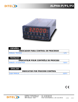 Ditel ALPHA-P Technical Manual
-
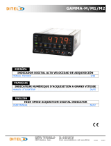 Ditel GAMMA-M Technical Manual
-
 Ditel MICRA-C Technical Manual
-
 Ditel RS2 Technical Manual
-
 Ditel RS4 Technical Manual
-
 Ditel JR/JR20-RES Technical Manual
-
 Ditel JR/JR20-VDC Technical Manual


Other documents
-
Vemer PC3R User manual
-
Dwyer Series LCI108/LCI108J User manual
-
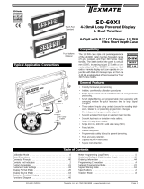 Texmate SD-60XI Owner's manual
-
Burster 9186-Vx1xx Owner's manual
-
 Texmate SD-802XAI Owner's manual
-
 Automation Direct ProSense DPM1-A-A2R-H User manual
-
red lion PCU User manual
-
-
Omega CN63100 and CN63300 Series Owner's manual
-


