Page is loading ...

Part number/version: 90000797_A
Release date: March 2008
www.digiembedded.com
Digi Connect
™
Wi-Wave
Hardware Reference
. . . . . . . . . . . . . . . . . . . . . . . . . . . . . . . . . . . . . . . . . . . . . . . . . . . . . . . . . . . . . . . . . .

Digi International, Inc.
11001 Bren Road East
Minnetonka, MN 55343 U.S.A.
United States: +1 877 912-3444
Other locations: +1 952 912-3444
www.digiembedded.com
©2008 Digi International Inc.
Printed in the United States of America. All rights reserved.
Digi, Digi International, the Digi logo, a Digi International Company, Jump Start Kit, ConnectCore, NET+,
NET+OS and NET+Works are trademarks or registered trademarks of Digi International, Inc. in the United
States and other countries worldwide. All other trademarks are the property of their respective owners.
Information in this document is subject to change without notice and does not represent a committment
on the part of Digi International.
Digi provides this document “as is,” without warranty of any kind, either expressed or implied, including,
but not limited to, the implied warranties of fitness or merchantability for a particular purpose. Digi may
make improvements and/or changes in this manual or in the product(s) and/or the program(s) described
in this manual at any time.
This product could include technical inaccuracies or typographical errors. Changes are made periodically
to the information herein; these changes may be incorporated in new editions of the publication.

5
Contents
. . . . . . . . . . . . . . . . . . . . . . . . . . . . . . . . . . . . . . . . . . . . . . . . . . . . . . . . . . . . . . . . . . . . .
Chapter 1:About the Module..................................................................9
Features.......................................................................................... 9
What’s on the module? ...................................................................... 10
Digi Connect Wi-Wave module edge connector ................................... 10
Digi Connect Wi-Wave module edge connector: Pinout ......................... 11
U.FL connectors........................................................................ 11
USB peripheral controller ................................................................... 12
802.11b/g modes and channels ............................................................ 12
Channel allocations ................................................................... 12
Receiver Sensitivity and Transmit Output Power................................. 13
Voltage regulators............................................................................ 13
Voltage monitor — Reset generator ....................................................... 13
LEDS ............................................................................................ 13
Power........................................................................................... 14
DISABLE signal.......................................................................... 14
Chapter 2: About the Development Board ...........................................15
What’s on the development board ........................................................ 15
Features................................................................................. 15
The development board .............................................................. 16
Unpopulated components ............................................................ 16
Digi Connect Wi-Wave module connector, J52 .......................................... 17
LEDs ............................................................................................ 19
LED DS1 ................................................................................. 19
LED DS2 ................................................................................. 19
Debug (signal) breakout header LEDs .............................................. 19
Switches and reset functionality ........................................................... 20
Voltage monitor........................................................................ 20
Alternative methods to trigger RESET# ............................................ 20
Power supply .................................................................................. 21
Input power jack, J3 .................................................................. 21
Input power supply .................................................................... 21
JTAG Breakout Header, P20 ................................................................ 22
JTAG breakout header signal map .................................................. 22
USB peripheral interface, J4................................................................ 23

6 Connect Wi-Wave Hardware Reference, Rev. A, 2/2008
USB peripheral jack, J4............................................................... 23
Debug breakout header, P21 ............................................................... 24
Debug breakout header signal map ................................................. 24
W_DISABLE# signal..................................................................... 24
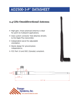
U.FL and RP-SMA connectors ............................................................... 25
U.FL connectors........................................................................ 25
U.FL cables ............................................................................. 25
RP-SMA connectors .................................................................... 26
For more information ................................................................. 26
Chapter 3: Using the Antenna ............................................................ 27
Necessary Conditions for Integration ............................................... 27
Connect Wi-Wave antenna configurations ......................................... 28
General information.......................................................................... 29
Antenna switch......................................................................... 29
Antenna specifications: 2 dBi Dipole ...................................................... 29
Attributes ............................................................................... 29
Dimensions.............................................................................. 29
Antenna strength (radiation pattern) diagram .................................... 31
Antenna specifications: 5.5 dBi Dipole.................................................... 32
Attributes ............................................................................... 32
Dimensions.............................................................................. 32
Radiation pattern: H-Plane (2.0 and 5.0 GHz) .................................... 33
Radiation pattern: E-plane (2.0 and 5.0 GHz) .................................... 34
End User Manual: RF Exposure Statements 34
Appendix A:Specifications .................................................................. 35
Environmental specifications ............................................................... 35
Mechanical dimensions ...................................................................... 35
Power requirements.......................................................................... 36
RF exposure statement ...................................................................... 36
Safety statements ............................................................................ 36
Module and development board dimensions ............................................. 37
Module dimensions .................................................................... 37
Development board dimensions ..................................................... 38
Appendix B: Certifications .................................................................. 39
FCC Part 15 Class B........................................................................... 39

7
Using this Guide
. . . . . . . . . . . . . . . . . . . . . . . . . . . . . . . . . . . . . . . . . . . . . . . . . . . . . . . . . . . . . . . . . . . . .
This guide provides information about the Digi Connect Wi-Wave embedded core
module.
Conventions used
in this guide
This table describes the typographic conventions used in this guide:
. . . . . . . . . . . . . . . . . . . . . . . . . . . . . . . . . . . . . . . . . . . . . . . . . . . . . . . . . . . . . . . . . . . . . . . . . . . . . . . . . .
Digi information
Related
documentation
For additional documentation, see the Documentation folder in the Start menu.
Documentation
updates
Digi occasionally provides documentation updates on the Web site
(www.digiembedded.com/support).
Be aware that if you see differences between the documentation you received in
your package and the documentation on the Web site, the Web site content is the
latest version.
This convention Is used for
italic type Emphasis, new terms, variables, and document titles.
monospaced type
Filenames, pathnames, and code examples.

8 Connect Wi-Wave Hardware Reference, Rev A 2/2008
Contact
information
For more information about your Digi products, or for customer service and
technical support, contact Digi International.
To contact Digi International by Use
Mail Digi International, Inc.
11001 Bren Road East
Minnetonka, MN 55343
U.S.A
World Wide Web www.digiembedded.com
Eservice Support www.digi.com/support/eservice/login.jsp
Telephone (U.S.) (952) 912-3444 or (877) 912-3444
Telephone (other locations) +1 (952) 912-3444 or +1 (877) 912-3444

9
Chapter 1:About the Module
The Digi Connect Wi-Wave module is an 802.11b/g WLAN communications module
for use in embedded applications. The module is a single circuit card packaged in a
PCI Express Mini Card form factor, and supports all the RF, analog, and digital
circuitry necessary to implement WLAN functionality. Using Digi’s baseband
processor technology, this module is the ideal choice for embedded applications
requiring long-term product availability in conjunction with reliability and easy
design integration.
The primary interface to the module is through a standards-compliant PCI Express
Mini Card edge connector, using a USB 2.0 full speed/high speed link for
communication with the host system.
Note:
The Digi Connect Wi-Wave edge connector pinout is compliant with the PCI
Express Mini Card Electromechanical Specification, Revision 1.1 (March 28,
2005) with this exception: the Digi Connect Wi-Wave has a 4-wire JTAG
programming interface mapped to pins 45, 47, 49, and 51.
The Digi Connect Wi-Wave module also provides a dual diversity antenna option
through two on-board U.FL connectors, which allow for cabling to remote 2.4 GHz
antennas.
. . . . . . . . . . . . . . . . . . . . . . . . . . . . . . . . . . . . . . . . . . . . . . . . . . . . . . . . . . . . . . . . . . . . . . . . . . . . . . . . . .
Features
Ultra-compact and standards-based form factor
Easy design integration through USB 2.0 full speed/high speed interface
Dual diversity antenna option through two on-module U.FL antenna connectors
Digi 802.11b/g baseband processor technology for long-term product
availability
-30°C to +60°C operating temperature for harsh environments
RoHS compliant design

What’s on the module?
10 Connect Wi-Wave Hardware Reference, Rev. A, 2/2008
. . . . . . . . . . . . . . . . . . . . . . . . . . . . . . . . . . . . . . . . . . . . . . . . . . . . . . . . . . . . . . . . . . . . . . . . . . . . . . . . . .
What’s on the module?
Digi Connect Wi-
Wave module
edge connector
The Digi Connect Wi-Wave module edge connector is a 52-pin connector whose
pinout follows the standard PCI Express Mini Card edge connector pinout as stated
in the PCI Express Mini Card Electromechanical Specification, Revision 1.1, with this
exception: JTAG signals are mapped onto pins 45, 47, 49, and 51. These signals are
reserved and not intended for user applications.
U.FL connectors
P1P2
Edge connector, P3

. . . . .
What’s on the module?
www.digiembedded.com 11
Digi Connect Wi-
Wave module
edge connector:
Pinout
The module edge connector is configured as shown (signal direction w.r.t Wi-Wave):
U.FL connectors The module uses two U.FL antenna connectors (P1 and P2) to allow for cabling to
embedded antennas or external antenna connectors. For more information, see
Chapter 3, “Using the Antenna.”
Pin Type WLAN Mini Card
signal
Pin Type WLAN Mini Card
signal
1 n/a No connect 2 In Vcc_3.3
3 n/a No connect 4 In GND
5 n/a No connect 6 n/a No connect
7 n/a No connect 8 n/a No connect
9 In GND 10 n/a No connect
11 n/a No connect 12 n/a No connect
13 n/a No connect 14 n/a No connect
15 In GND 16 n/a No connect
Key Key
17 n/a No connect 18 In GND
19 n/a No connect 20 In W_DISABLE#
21 In GND 22 In RESET (PERST#)
23 n/a No connect 24 n/a No connect
25 n/a No connect 26 In GND
27 In GND 28 n/a No connect
29 In GND 30 n/a No connect
31 n/a No connect 32 n/a No connect
33 n/a No connect 34 In GND
35 In GND 36 I/O USB_D-
37 n/a No connect 38 I/O USB_D+
39 n/a No connect 40 In GND
41 n/a No connect 42 Out LED_WWAN#
43 n/a No connect 44 Out LED_WLAN#
45 Rsvd (In) JTAG_TCK 46 Out LED_WPAN#
47 Rsvd (In) JTAG_TMS 48 n/a No connect
49 Rsvd (Out) JTAG_TDO 50 In GND
51 Rsvd (In) JTAG_TDI 52 In Vcc_3.3

USB peripheral controller
12 Connect Wi-Wave Hardware Reference, Rev. A, 2/2008
. . . . . . . . . . . . . . . . . . . . . . . . . . . . . . . . . . . . . . . . . . . . . . . . . . . . . . . . . . . . . . . . . . . . . . . . . . . . . . . . . .
USB peripheral controller
The module uses a peripheral USB controller to interface to either a full speed or
high speed USB 2.0 link. The link first tries to communicate to the host system
board at the high speed USB rate (480 Mbps). If not successful, the link reverts to
the full speed USB rate (12 Mbps). This link is used for all communication between
the module and the host system board.
Note:
The Digi Connect Wi-Wave module does not support low-speed USB
connections.
. . . . . . . . . . . . . . . . . . . . . . . . . . . . . . . . . . . . . . . . . . . . . . . . . . . . . . . . . . . . . . . . . . . . . . . . . . . . . . . . . .
802.11b/g modes and channels
The Digi Connect Wi-Wave transmits and receives data at up to 11 Mbps when
operating in 802.11b mode and up to 54 Mbps when operating in 802.11g mode. It
supports these 802.11b/g channels:
Channels 1 through 11 for North America (2.401 GHz–2.473 GHz)
Channels 1 through 13 for Europe (2.401 GHz–2.483 GHz)
Channels 1 through 14 for Asia (2.401 GHz–2.495 GHz)
Channel
allocations
Channel Center frequency
(MHz)
Frequency spread
(MHz - MHz)
1 2412 2401 - 2423
2 2417 2406 - 2428
3 2422 2411 - 2433
4 2427 2416 - 2438
5 2432 2421 - 2443
6 2437 2426 - 2448
7 2442 2431 - 2453
8 2447 2436 - 2458
9 2452 2441 - 2463
10 2457 2446 - 2468
11 2462 2451 - 2473
12 2467 2456 - 2478
13 2472 2461 - 2483
14 2484 2473 - 2495

. . . . .
Voltage regulators
www.digiembedded.com 13
Receiver
Sensitivity and
Transmit Output
Power
-71 dBm @ 54 Mbps
-81 dBm @ 11 Mbps
-88 dBm @ 6 Mbps
-93 dBm @ 1 Mbps
13.8 dBm OFDM
17 dBm PSK/CCK
. . . . . . . . . . . . . . . . . . . . . . . . . . . . . . . . . . . . . . . . . . . . . . . . . . . . . . . . . . . . . . . . . . . . . . . . . . . . . . . . . .
Voltage regulators
The module takes in 3.3V±9% (3.00V to 3.60V) as its main input power. This power is
filtered and used as a 3.3V supply to portions of the digital logic. This power also
acts as input to dedicated on-board voltage regulators.
. . . . . . . . . . . . . . . . . . . . . . . . . . . . . . . . . . . . . . . . . . . . . . . . . . . . . . . . . . . . . . . . . . . . . . . . . . . . . . . . . .
Voltage monitor — Reset generator
The module does not provide a voltage monitor or automatic reset signal generator;
rather, the module uses a reset signal generated by the host system board.
. . . . . . . . . . . . . . . . . . . . . . . . . . . . . . . . . . . . . . . . . . . . . . . . . . . . . . . . . . . . . . . . . . . . . . . . . . . . . . . . . .
LEDS
The module does not have any on-board LEDs, but it drives the LED_WLAN# signal
(pin 44) to indicate WLAN association and transmit/receive activity. This table
shows the different LED states:
LED state Indication
Off Not powered on
On Associated and authenticated
Slow blink Not associated or authenticated
Intermittent blink Transmit/receive activity

Power
14 Connect Wi-Wave Hardware Reference, Rev. A, 2/2008
. . . . . . . . . . . . . . . . . . . . . . . . . . . . . . . . . . . . . . . . . . . . . . . . . . . . . . . . . . . . . . . . . . . . . . . . . . . . . . . . . .
Power
The module requires only +3.3 VDC, 750 mA max. This power must be a well-
regulated +3.3V supply due to limited supply filtering in the module. The digital
inputs and outputs are 3.3V CMOS compatible. See “Power requirements” on
page 36 for specifications.
DISABLE signal The module supports the active low
W_DISABLE# signal (pin 20) as specified in the PCI
Express Mini Card Electromechanical Specification. This signal not only disables the
power supplies to the radio portion of the module, it also powers down additional
portions of the module to reduce power consumption to a minimum.

15
Chapter 2:About the
Development Board
The development board is designed for product evaluation and development
purposes. In addition to the Digi Connect Wi-Wave connector, the development
board provides several breakout connectors and interfaces.
. . . . . . . . . . . . . . . . . . . . . . . . . . . . . . . . . . . . . . . . . . . . . . . . . . . . . . . . . . . . . . . . . . . . . . . . . . . . . . . . . .
What’s on the development board
Features Digi Connect Wi-Wave connector
Pushbutton reset switch and under voltage reset logic
External USB Type B connector USB peripheral interface
Additional signal headers for user access
Two U.FL RP-SMA antenna connectors
-30°C to +75°C ambient operating temperature
RoHS compliant design

ABOUT THE DEVELOPMENT BOARD
What’s on the development board
16 Connect Wi-Wave Hardware Reference, Rev A 2/2008
The development
board
Unpopulated
components
There are components on the development board that are currently not populated.
These components allow the development board to be used in other applications.

. . . . .
ABOUT THE DEVELOPMENT BOARD
Digi Connect Wi-Wave module connector, J52
www.digiembedded.com 17
. . . . . . . . . . . . . . . . . . . . . . . . . . . . . . . . . . . . . . . . . . . . . . . . . . . . . . . . . . . . . . . . . . . . . . . . . . . . . . . . . .
Digi Connect Wi-Wave module connector, J52
Place the Digi Connect Wi-Wave module into the connector and support bracket,
J52, on the development board.
The Digi Connect Wi-Wave module connector is a 52-pin connector that conforms to
the PCI Express Mini Card Electromechanical Specification, Rev. 1.1, with additional
non-standard connections (to the reserved pins on the standard connector).

ABOUT THE DEVELOPMENT BOARD
Digi Connect Wi-Wave module connector, J52
18 Connect Wi-Wave Hardware Reference, Rev A 2/2008
Note:
Signal direction w.r.t PCIe Mini Card.
Pin Type Signal Pin Type Signal
1 n/a No connect 2 In Vcc_3.3
3 n/a No connect 4 In GND
5 n/a No connect 6 n/a No connect
7 n/a No connect 8 Out UIM_PWR (C1)
9 In GND 10 I/O UIM_DATA (C7)
11 n/a No connect 12 Out UIM_CLK (C3)
13 n/a No connect 14 Out UIM_RESET (C2)
15 In GND 16 Out UIM_Vpp (C6)
Key Key Key Key Key Key
17 I/O UIM C8 18 In GND
19 I/O UIM C4 20 In W_DISABLE#
21 In GND 22 In RESET (PERST#)
23 n/a No connect 24 n/a No connect
25 n/a No connect 26 In GND
27 In GND 28 n/a No connect
29 In GND 30 n/a No connect
31 n/a No connect 32 n/a No connect
33 n/a No connect 34 In GND
35 In GND 36 I/O USB_D-
37 n/a No connect 38 I/O USB_D+
39 n/a No connect 40 In GND
41 n/a No connect 42 Out LED_WWAN#
43 n/a No connect 44 Out LED_WLAN#
45 n/a or In No connect or JTAG_TCK 46 Out LED_WPAN#
47 n/a or In No connect or JTAG_TMS 48 n/a No connect
49 n/a or Out No connect or JTAG_TDO 50 In GND
51 n/a or In No connect or JTAG_TDI 52 In Vcc_3.3

. . . . .
ABOUT THE DEVELOPMENT BOARD
LEDs
www.digiembedded.com 19
. . . . . . . . . . . . . . . . . . . . . . . . . . . . . . . . . . . . . . . . . . . . . . . . . . . . . . . . . . . . . . . . . . . . . . . . . . . . . . . . . .
LEDs
LED DS1 The switching regulator is adjusted to output +3.3V
DC
± 5% or better. LED DS1 lights
up when the regulator outputs +3.3V power. See “Power supply” on page 21 for
more information.
LED DS2 LED DS2 lights up when the host system supplies power over the USB bus. This LED
indicates that the host platform has recognized the attachment of a USB peripheral
device on the USB bus. See “USB peripheral interface, J4” on page 23 for more
information.
Debug (signal)
breakout header
LEDs
Five LEDs are associated with the debug breakout header (J4):
DISABLE, DS3: Lights up when the W_DISABLE# signal is asserted.
RST, DS4: Lights up when the RESET# signal is asserted.
WAN, DS5: Reserved for future use.
LAN, DS6: Lights up when the module drives the LED_WLAN# signal.
PAN, DS7: Reserved for future use.
See “Debug breakout header, P21” on page 24 for more information.
LEDs: DS3-DS7

ABOUT THE DEVELOPMENT BOARD
Switches and reset functionality
20 Connect Wi-Wave Hardware Reference, Rev A 2/2008
. . . . . . . . . . . . . . . . . . . . . . . . . . . . . . . . . . . . . . . . . . . . . . . . . . . . . . . . . . . . . . . . . . . . . . . . . . . . . . . . . .
Switches and reset functionality
Voltage monitor The development board provides a power supply voltage monitor and reset
generator. When the +3.3V regulated supply voltage drops below 2.93V, the reset
signal — RESET# — is asserted for a minimum of 140 msec. This signal is connected
to the Digi Connect Wi-Wave edge connector (pin 22), as well as to the debug
breakout header for monitoring.
Alternative
methods to trigger
RESET#
In addition to supply voltage monitoring, reset logic can be triggered in two other
ways. The RESET# signal is asserted when you do one of these actions:
Manually push SW1, a pushbutton reset switch on the development board
Pull low pin 15 on the JTAG breakout header, P20.

. . . . .
ABOUT THE DEVELOPMENT BOARD
Power supply
www.digiembedded.com 21
. . . . . . . . . . . . . . . . . . . . . . . . . . . . . . . . . . . . . . . . . . . . . . . . . . . . . . . . . . . . . . . . . . . . . . . . . . . . . . . . . .
Power supply
The development board provides a 3.3V
DC
switching power supply. Either a bench
power supply or an AC wall adapter supplies input power to the development board.
The required input voltage range is 9–30V
DC
.
Input power jack,
J3
The input power jack, J3, is a barrel connector that accepts 9-30 VDC. The power
jack is labeled J3 on the development board. This figure schematically represents
the power jack’s polarity:
Input power
supply
The output current of this regulator is limited to 2.4 amps and the Digi Connect Wi-
Wave module draws no more than .750 amps. Using these values as a guideline, and
using an 80% efficiency for the switching regulator, the input power supply should
be rated to provide at least 3 watts of power.
Important:
The development board can use USB power as the power source for the
3.3V regulator. This is accomplished by simply connecting the USB
Ground 9-30VDC +/- 5%

ABOUT THE DEVELOPMENT BOARD
JTAG Breakout Header, P20
22 Connect Wi-Wave Hardware Reference, Rev A 2/2008
cable to the development board. However, Digi recommends using the
supplied AC wall adapter.
. . . . . . . . . . . . . . . . . . . . . . . . . . . . . . . . . . . . . . . . . . . . . . . . . . . . . . . . . . . . . . . . . . . . . . . . . . . . . . . . . .
JTAG Breakout Header, P20
JTAG breakout
header signal map
The development board provides a 20-pin JTAG header, P20. The pins are allocated
as shown:
Pin Type Signal Pin Type Signal
1 Monitor pt +3.3V 2 Monitor pt +3.3V
3n/aNo connect 4Monitor ptGND
5 In JTAG TDI 6 Monitor pt GND
7 In JTAG TMS 8 Monitor pt GND
9 In JTAG TCK 10 Monitor pt GND
11 n/a No connect 12 Monitor pt GND
13 Out JTAG TDO 14 Monitor pt GND
15 In RST# TRIGGER 16 Monitor pt GND
17 n/a No connect 18 Monitor pt GND
19 n/a No connect 20 Monitor pt GND
/