Page is loading ...

ConnectCard™
i.MX28™
Hardware Reference Manual

Revision history—90002181
Revision Date Description
G September, 2013 Replaced ConnectCore references with ConnectCard.
H November, 2013 Corrected errors in pinout table.
J May, 2014 Updated DC power output section to clarify purpose of
3.3V line, correct pinout for i.MX287 processor, apply
new style and cover page.
K July, 2015 Edited pins 26 and 31 in standard 18-bit color pinout
table.
L June, 2017 Updated branding and added statements for RED
compliance.
Trademarks and copyright
Digi, Digi International, and the Digi logo are trademarks or registered trademarks in the United
States and other countries worldwide. All other trademarks mentioned in this document are the
property of their respective owners.
© 2017 Digi International Inc. All rights reserved.
Disclaimers
Information in this document is subject to change without notice and does not represent a
commitment on the part of Digi International. Digi provides this document “as is,” without warranty of
any kind, expressed or implied, including, but not limited to, the implied warranties of fitness or
merchantability for a particular purpose. Digi may make improvements and/or changes in this manual
or in the product(s) and/or the program(s) described in this manual at any time.
Warranty
To view product warranty information, go to the following website:
www.digi.com/howtobuy/terms
Send comments
Documentation feedback: To provide feedback on this document, send your comments to
techcomm@digi.com.
Customer support
Digi Technical Support: Digi offers multiple technical support plans and service packages to help our
customers get the most out of their Digi product. For information on Technical Support plans and
pricing, contact us at +1 952.912.3444 or visit us at www.digi.com/support.
ConnectCard for i.MX28 Hardware Reference Manual
2

Contents
Chapter 1: ConnectCard for i.MX28 features and functionality
Introduction 6
i.MX28 features and functionality 6
Block diagram 8
CPU - NXP i.MX28X 8
ConnectCard for i.MX28 9
Module pinout 10
52-pin PCle edge connector 10
Pinout 10
Pinout for pins 50 and 52 15
Available features 16
Available features for i.MX280 and i.MX287 16
Chapter 2: About the development board
Introduction 27
What’s on the development board? 27
The development board 29
Development board setup 33
Connector, switch, and jumper locations 37
Boot mode 38
Switch location 39
Development board button functions 39
Button locations 41
DUART (Console) and I2C0 42
AUART1, ENET0, LRADC4, LRADC5, and User LEDs 43
AUART4, SSP3, I2S (Audio), LRADC6, and XBee 46
AUART2, AUART3, CAN1, Ethernet, and USB host 51
SD CARD, SSP1, LRADC0, LRADC1, LRADC2, and LRADC3 55
CAN0, HSADC, and 1-wire 57
LCD, ETM, JTAG, USB OTG (USB0) 59
Chapter 3: Regulatory information
Agency certifications 61
United States FCC 61
FCC-approved antennas 62
Approved antennas for the ConnectCard for i.MX28 Wi-Fi modules 63
Europe 64
OEM Labeling Requirements 64
ConnectCard for i.MX28 Hardware Reference Manual
3

ConnectCard for i.MX28 Hardware Reference Manual
4
Declaration of Conformity (DoC) statement 64
Approved antennas 64
Canada (IC) 65
Labeling requirements 65
Transmitters with detachable antennas 65
Detachable antenna 65
Australia (C-Tick) 66
Appendix A: Module specifications
Mechanical specifications 68
Dimensional drawing 68
Environmental specifications 68
Network interface 69
Digi part number A24-HASM-450 69
Digi part number 29000146 70
Taoglas PC.11.07.0100A 71
Taoglas FXP.830.07.0100C 72
Ethernet 1 74
Ethernet 2 74
WLAN 74
5 GHz HT 20 and HT40 channels available 77
Receive sensitivity 78
Transmit power 78
Electrical characteristics 79
Absolute maximum ratings 79
Voltage supplies 79
Supply current 79
GPIO DC parameters 80
Agency approvals 80
Appendix B: ConnectCard for i.MX28 module dimensions
Mini PCI Express Connector design recommendations 83
Maximum power and frequency specifications


Chapter 1: ConnectCard for i.MX28 features and functionality Introduction
ConnectCard for i.MX28 Hardware Reference Manual
6
Introduction
The ConnectCard™ for i.MX28 is a cost-effective, small-footprint wireless embedded module solution
that is designed for connected devices in healthcare and other markets.
The module is based on the NXP® i.MX28 processor family with a high-performance ARM 9 core,
multimedia options, and a complete set of peripherals.
Combined with a Qualcom-Atheros 802.11 and Bluetooth module featuring data rates up to 150 Mbps
the ConnectCard for i.MX28 is capable of communicating with a vast number of peripheral devices
over many different networks.
The module combines the fast integration, reliability and design flexibility of an off-the-shelf System-
on Module (SOM) with complete out-of-the-box software development support for platforms such as
Digi® Embedded Linux ®and Timesys® LinuxLink®.
Complete and cost-efficient Digi Jump Start Kits™ enable professional embedded product
development with reduced design risk and time-to-market.
i.MX28 features and functionality
The ConnectCard for i.MX28 module is based on the i.MX28 processor series from NXP. This processor
offers a high number of interfaces. Most of these interfaces are multiplexed and are not available
simultaneously. Not all features are available on all variations of the module. More in-depth
information can be found in the i.MX28 Applications Processor Reference Manual at www.nxp.com. The
i.MX28 processor uses an ARM 926 core with on-chip RISC (Reduced Instruction Set Computer).
The ConnectCard for i.MX28 module has the following i.MX28 features:
n LRADC (Low Resolution ADC)
n HSADC (High Speed ADC)
n GPIO (General Purpose Input Output)
n SD/SDIO/MMC (Secure Digital/ Secure Digital Input Output/ Multi-Media Card)
n UART (Universal Asynchronous Receiver/Transmitter)
n DUART (Debug Universal Asynchronous Receiver/Transmitter)
n SPI (Serial Peripheral Interface)
n I2C (Inter-Integrated Circuit)
n CAN (Controller Area Network)
n USB OTG (Universal Serial Bus On-the-Go)
n USB Host (Universal Serial Bus)
n ENET (Ethernet)
n SAIF (Serial Audio Interface)
n PWM (Pulse Width Modulator)
n LCD (Liquid Crystal Display)
n ETM (Embedded Trace Macrocell)
n JTAG (Joint Test Action Group)
n 802.11 abgn and Bluetooth
n Flash memory

Chapter 1: ConnectCard for i.MX28 features and functionality i.MX28 features and functionality
ConnectCard for i.MX28 Hardware Reference Manual
7
n DDR2 memory
n One-Wire interface
n Power supply options - battery and DC

Chapter 1: ConnectCard for i.MX28 features and functionality Block diagram
ConnectCard for i.MX28 Hardware Reference Manual
8
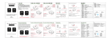
Block diagram
The following figures show the block diagram of the NXP i.MX285 CPU and the block diagram of the
ConnectCard for i.MX28 module.
CPU - NXP i.MX28X

Chapter 1: ConnectCard for i.MX28 features and functionality Block diagram
ConnectCard for i.MX28 Hardware Reference Manual
9
ConnectCard for i.MX28

Chapter 1: ConnectCard for i.MX28 features and functionality Module pinout
ConnectCard for i.MX28 Hardware Reference Manual
10
Module pinout
The module has two connectors: The 52-pin PCIe edge connector, and the 31-pin LCD connector.
52-pin PCle edge connector
The top side of the module has the shield, and the bottom side of the module has the i.MX28X. Pin
numbering is shown below:
Pinout
Pin Pin name
Available
on
i.MX287
Available
on
i.MX280 Mux 0 Mux 1 Mux 2 Mux 3
1 ENET0_
TX+
X X
3 ENET0_TX- X X
5 GND X X
7
AUART4_
CTS
X X SAIF0_
MCLK
PWM_3 AUART4_CTS GPIO3_
20
X SSP3_
SS0
AUART4_CTS ENET1_1588_
EVENT1_ IN
GPIO2_
27
9 **AUART4_
RTS
X X SAIF0_
LRCLK
PWM4 AUART4_RST GPIO3_
21
X SSP3_
CMD
AUART4_RX ENET1_1588_
EVENT0_ IN
GPIO2_
25

Chapter 1: ConnectCard for i.MX28 features and functionality Module pinout
ConnectCard for i.MX28 Hardware Reference Manual
11
Pin Pin name
Available
on
i.MX287
Available
on
i.MX280 Mux 0 Mux 1 Mux 2 Mux 3
11 **AUART4_
RX
X X SAIF0_
BITCLK
PWM_5 AUART4_RX GPIO3_
22
X SSP3_D0 AUART4_RTS ENET1_1588_
EVENT1_ OUT
GPIO2_
26
13 AUART4_
TX
X X SAIF0_
SDAT0
PWM_6 AUART4_TX GPIO3_
23
X SSP3_
SCK
AUART4_TX ENET1_1588_
EVENT0_ OUT
GPIO2_
24
15 Pswitch X X
GAP
17 USB0_DM X X
19 USB0_DP X X
21 USB0_ID
X
X PWM_2 USB0_ID
USB1
_OVERCURRENT
GPIO3_
18
23 Battery X X
25 HSADC0 X X HSADC0
27 CAN0_RX X GPMI_
READY3
CAN0_RX HSADC_TRIGGER GPIO0_
23
29 CAN0_TX X GPMI_
READY2
CAN0_TX ENET0_TX_ER GPIO0_
22
31 SSP1_SS
X SSP1_D3 SSP2_D7 ENET0_1588_
EVENT3_ IN
GPIO2_
15
X X LRADC0
33 SSP1_
MOSI
X SSP1_
CMD
SSP2_D2 ENET0_1588_
EVENT2_ IN
GPIO2_
13
X X LRADC1
35 SSP1_
MISO
X SSP1_D0 SSP2_D6 ENET0_1588_
EVENT3_OUT
GPIO2_
14
X X LRADC2
37 SSP1_SCK
X SSP1_
SCK
SSP2_D1 ENET0_1588_
EVENT2
_OUT
GPIO2_
12
X X LRADC3

Chapter 1: ConnectCard for i.MX28 features and functionality Module pinout
ConnectCard for i.MX28 Hardware Reference Manual
12
Pin Pin name
Available
on
i.MX287
Available
on
i.MX280 Mux 0 Mux 1 Mux 2 Mux 3
39 AUART1_
CTS
X AUART1_
CTS
USB0_
OVERCURRENT
TIMROT_ROTARYA GPIO3_
6
X X LRADC4
41 AUART1_
RTS
X AUART1_
RTS
USB0_ID TIMROT_
ROTARYB
GPIO3_
7
X X LRADC5
43 AUART1_
TX
X X AUART1_
TX
SSP3_CARD
_DETECT
PWM1 GPIO3_
5
45 AUART1_
RX
X X AUART1_
RX
SSP2_CARD
_DETECT
PWM0 GPIO3_
4
47 GND X X
49 ENET1_
TX+
X
51 ENET1_TX- X
2 ENET0_
RX+
X X
4 ENET0_RX- X X
6 VDD_5V X X
8 I2C1_SCL X X PWM0 I2C1_SCL DUART_RX GPIO3_
16
10 I2C1_SDA X X PWM1 I2C1_SDA DUART_TX GPIO3_
17
12 DUART_RX X X I2C0_SCL TIMROT_
ROTARYA
DUART_RX GPIO3_
24
14 DUART_TX X X I2C0_
SDA
TIMROT_
ROTARYB
DUART_TX GPIO3_
25
16 RESET X X
GAP
18 SSP0_CMD X X SSP0_
CMD
GPIO2_
8
20 SSP0_
DATA0
X X SSP0_
DATA0
GPIO2_
0

Chapter 1: ConnectCard for i.MX28 features and functionality Module pinout
ConnectCard for i.MX28 Hardware Reference Manual
13
Pin Pin name
Available
on
i.MX287
Available
on
i.MX280 Mux 0 Mux 1 Mux 2 Mux 3
22 SSP0_
DATA1
X X SSP0_
DATA1
GPIO2_
1
X AUART3_
CTS
CAN1_TX ENET0_1588_
EVENT1
_OUT
GPIO3_
14
24 SSP0_
DATA2
X X SSP0_
DATA2
GPIO2_
2
X AUART3_
RTS
CAN1_RX ENET0_1588_
EVENT1_ IN
GPIO3_
15
26 SSP0_
DATA3
X X SSP0_
DATA3
GPIO2_
3
28 SSP0_
SCLK
X X SSP0_
SCK
GPIO2_
10
30 SSP0_
CARD
_DETECT
X X SSP0_
CARD
_DETECT
GPIO2_
9
32 LRADC6 /
X X LRADC6
X LCD_
VSYNC
SAIF1_DATA0 GPIO_
1_28
34 i.MX28 3.3V
Output
X X
36
AUART2_
CTS
X AUART2_
CTS
I2C1_SCL SAIF1_BITCLK GPIO3_
10
One-Wire X X
38 AUART2_
RTS
X AUART2_
RTS
I2C1_SDA SAIF1_LRCLK GPIO3_
11
40 AUART2_
RX
X AUART2_
RX
SSP3_D1 SSP3_D4 GPIO3_
8
42 AUART2_
TX
X AUART2_
TX
SSP3_D2 SSP3_D5 GPIO3_
9
44 CAN1_RX
X GPMI_
CE3N
CAN1_RX SAIF1_MCLK GPIO0_
19
X AUART3_
RX
CAN0_TX ENET0_1588_
EVENT0
_OUT
GPIO3_
12

Chapter 1: ConnectCard for i.MX28 features and functionality Module pinout
ConnectCard for i.MX28 Hardware Reference Manual
14
Pin Pin name
Available
on
i.MX287
Available
on
i.MX280 Mux 0 Mux 1 Mux 2 Mux 3
46 CAN1_TX
X GPMI_
CE2N
CAN1_TX ENET0_RX_ER GPIO0_
18
X AUART3_
TX
CAN0_RX ENET0_1588_
EVENT0_ IN
GPIO3_
13
48 VDD_5V X X
50
ENET1_
RX+
X
USB1_DM X USB1_
DM
52
ENET1_RX- X
USB1_DP X USB1_DP

Chapter 1: ConnectCard for i.MX28 features and functionality Module pinout
ConnectCard for i.MX28 Hardware Reference Manual
15
Pinout for pins 50 and 52
Pin name
Available on 2-
ENET Variants
Available on 1-
ENET Variants Mux 0
Mux 1 Mux 2 Mux 3
50
ENET1_RX+ X
USB1_DM X USB1_DM
52
ENET1_RX- X
USB1_DP X USB1_DP
Notice:
For product applications in a harsh environments (extreme temperature cycling and/or high vibration
locations), Digi strongly recommends applying a thin layer of dielectric grease (using a cotton swab or
equivalent) on the top and bottom of the module edge connector and to the inside of the mating
connector to prevent unexpected failures in production environments.
Digi recommends the use for Dow Corning® #4 Electrical Insulating Compound (Dielectric Grease). A
local distributor can be located via the link below:
http://www.dowcorning.com/applications/search/distributor/default.aspx
Apply a thin layer of dielectric grease to the top and bottom of the PCIe edge connector prior to
inserting the ConnectCard for i.MX28 module into the PCIe connector.
The microprocessor used on this module, like all CMOS devices, can be driven into a latch-up condition
if any I/O pin is driven outside of its associated power rail. Care must be taken to:
n Never drive an I/O pin beyond its positive rail or below ground.
n Never drive an I/O pin from an external power source during the power-on or reset sequences.
n Never hot-swap the module or interrupt its ground connection to external circuitry.
Latch-up is a condition that can cause excessive current draw and result in excessive heating of the
microprocessor or its power supplies. This excessive heating can permanently damage the
microprocessor and/or its supporting components.

Chapter 1: ConnectCard for i.MX28 features and functionality Available features
ConnectCard for i.MX28 Hardware Reference Manual
16
Available features
Standard variants are available with either the i.MX280 or i.MX287. Not all features are available on all
variants. For custom variants see your Digi International sales person.
Available features for i.MX280 and i.MX287
Function i.MX280 i.MX287
LCD Interface - Yes
Touch Screen - Yes
Ethernet x1 x2
L2 Switch - Yes
CAN - x2
12-bit ADC x7 x7
12-bit ADC x7 x7
USB 2.0 OTG HS with HS
PHY x1
OTG HS with HS
PHY x1
HS Host with HS
PHY x1
HS Host with HS
PHY x1
SDIO x1 x1
SPI x2 x3
Application UART x2 x4
Debug UART x1 x1
PWM x8 x8
S/PDIF Tx - Yes
Security Yes Yes
Thermal considerations
Heat dissipation of the i.MX28 processor is highly dependent on the selected clock speed and the
peripherals it is supporting. NXP specifies the maximum allowed junction temperature of the
processor to be limited to 105C, which translates to the following processor case temperatures:
Processor speed Max ambient temperature without thermal pad Max case temperature
454 MHz 59 C 84 C
360 MHz 68 C 88 C
261 MHz 69 C 88 C
64 MHz 99 C 102 C

Chapter 1: ConnectCard for i.MX28 features and functionality Available features
ConnectCard for i.MX28 Hardware Reference Manual
17
At high clock rates, the i.MX28 pulls more current. The ConnectCard for i.MX28 has been built to
function up to 65C at full clock speed without a thermal pad attached (not included in the
development kit) between the processor and the development board, and has been checked up to
75C with the thermal pad attached. There is a large ground area left open on the development board
under the module to accommodate the thermal pad. Bergquist makes thermal pad material in various
thicknesses. The CCi.MX28 has been characterized using a combination of 2500S20 and 2000S40 pads
from Bergquist. Consult the NXP data sheet for the i.MX28 for thermal requirements.
When developing designs using the ConnectCard for i.MX28, ensure that the application does not
exceed the rating maximums above. Case temperature can be measured using an external probe on
the center of the i.MX28 processor package, and the junction temperature can be monitored in
software through an on-die temperature sensor provided in the i.MX processor.
Because of the limitation above, active and/or passive thermal management may be required
(thermal pad, airflow, clocking, and so on) like the Bergquist 2500S20 and 2000S40 thermal pads.
For more information on thermal consideration with the i.MX28 processor see the NXP i.MX28 data
sheet.
31-pin LCD, JTAG, and ETM connector
The module uses a 31-pin ZIF connector for the LCD, JTAG and ETM connections. These pins can also
be used for GPIO functions. A list of possible connectors is shown below. Note that the list is not all
inclusive:
Manufacturer Part number
FCI SFV31R-1STE1HLF
FCI SFV31R-1STE1LF
TYCO ELECTRONICS 3-1734839-1
The standard connection is 18-bit color, and the CC-WMX-PF58-TK-JT comes with this option.
Standard 18-bit color pinout
Pin Pin name i.MX28 Mux 0 Mux 1 Mux 2 Mux 3
1 LCD_DOTCLK N1 LCD_
DOTCLK
SAIF1_
MCLK
ETM_TCLK GPIO1_
30
2 LCD_VSYNC M6 LCD_RESET LCD_VSYNC LCD_RESET / LCD_
VSYNC
GPIO3_
30
3 LCD_HSYNC M1 LCD_HSYNC SAIF1_
SDATA1
EMT_TCTL GPIO1_
29
4 LCD_ENABLE N5 LCD_
ENABLE
LCD_
ENABLE
GPIO1_
31
5 LCD_WR_RWN / ETM_
TCLK
K1 LCD_WR_
RWN
LCD_HSYNC ETM_TCLK GPIO1_
25

Chapter 1: ConnectCard for i.MX28 features and functionality Available features
ConnectCard for i.MX28 Hardware Reference Manual
18
Pin Pin name i.MX28 Mux 0 Mux 1 Mux 2 Mux 3
6 LCD_D17 R3 LCD_D17 ETM_DA6 GPIO1_
17
7 LCD_D16 T3 LCD_D16 ETM_DA7 GPIO1_
16
8 LCD_D15 / ETM_DA15 U3 LCD_D15 ETM_DA15 GPIO1_
15
9 LCD_D14 / ETM_DA14 U2 LCD_D14 ETM_DA14 GPIO1_
14
10 LCD_D13 / ETM_DA13 T2 LCD_D13 ETM_DA13 GPIO1_
13
11 LCD_D12 / ETM_DA12 T1 LCD_D12 ETM_DA12 GPIO1_
12
12 LCD_D11 / ETM_DA11 R2 LCD_D11 ETM_DA11 GPIO1_
11
13 LCD_D10 / ETM_DA10 R1 LCD_D10 ETM_DA10 GPIO1_
10
14 LCD_D09 / ETM_DA9 P3 LCD_D09 ETM_DA4 ETM_DA9 GPIO1_
9
15 LCD_D08 / ETM_DA8 P2 LCD_D08 ETM_DA3 ETM_DA8 GPIO1_
8
16 LCD_D07 / ETM_DA7 P1 LCD_D07 ETM_DA7 GPIO1_
7
17 LCD_D06 / ETM_DA6 N2 LCD_D06 ETM_DA6 GPIO1-6
18 LCD_D05 / ETM_DA5 M3 LCD_D05 ETM_DA5 GPIO1_
5
19 LCD_D04 / ETM_DA4 M2 LCD_D04 ETM_DA9 ETM_DA4 GPIO1_
4
20 LCD_D03 / ETM_DA3 L3 LCD_D03 ETM_DA8 ETM_DA3 GPIO1_
3
21 LCD_D02 / ETM_DA2 L2 LCD_D02 ETM_DA2 GPIO1_
2
22 LCD_D01 / ETM_DA1 K3 LCD_D01 ETM_DA1 GPIO1_
1
23 LCD_D00 / ETM_DA0 K2 LCD_D00 ETM_DA0 GPIO1_
0

Chapter 1: ConnectCard for i.MX28 features and functionality Available features
ConnectCard for i.MX28 Hardware Reference Manual
19
Pin Pin name i.MX28 Mux 0 Mux 1 Mux 2 Mux 3
24 ETM_TCTL P4 LCD_RD_E LCD_VSYNC ETM_TCTL GPIO1_
24
25 LCD_CS /
Touch_Interrupt
P5 LCD_CS GPIO1_
27
26 JTAG_TRST# D14
27 JTAG_TMS D12
28 JTAG_TDO E13
29 JTAG_TDI E12
30 JTAG_TCK E11
31 JTAG-RTCK E14 JTAG_RTCK GP104_
20
(default)
Provisions have been made on the module for 24-bit color without the JTAG connections.
24-bit color pinout (without JTAG)
Pin Pin name
i.MX28
pin Mux 0 Mux 1 Mux 2
1 LCD_DOTCLK N1 LCD_DOTCLK SAIF1_MCLK ETM_
TCLK
2 LCD_VSYNC M6 LCD_RESET LCD_VSYNC
3 LCD_HSYNC M1 LCD_HSYNC SAIF1_SDATA1 EMT_
TCTL
4 LCD_ENABLE N5 LCD_ENABLE
5 LCD_WR_RWN / ETM_
TCLK
K1 LCD_WR_
RWN
LCD_HSYNC ETM_
TCLK
6 LCD_D17 R3 LCD_D17 ETM_DA6
7 LCD_D16 T3 LCD_D16 ETM_DA7
8 LCD_D15 / ETM_DA15 U3 LCD_D15 ETM_
DA15
9 LCD_D14 / ETM_DA14 U2 LCD_D14 ETM_
DA14
10 LCD_D13 / ETM_DA13 T2 LCD_D13 ETM_
DA13

Chapter 1: ConnectCard for i.MX28 features and functionality Available features
ConnectCard for i.MX28 Hardware Reference Manual
20
Pin Pin name
i.MX28
pin Mux 0 Mux 1 Mux 2
11 LCD_D12 / ETM_DA12 T1 LCD_D12 ETM_
DA12
12 LCD_D11 / ETM_DA11 R2 LCD_D11 ETM_
DA11
13 LCD_D10 / ETM_DA10 R1 LCD_D10 ETM_
DA10
14 LCD_D09 / ETM_DA9 P3 LCD_D09 ETM_DA4 ETM_DA9
15 LCD_D08 / ETM_DA8 P2 LCD_D08 ETM_DA3 ETM_DA8
16 LCD_D07 / ETM_DA7 P1 LCD_D07 ETM_DA7
17 LCD_D06 / ETM_DA6 N2 LCD_D06 ETM_DA6
18 LCD_D05 / ETM_DA5 M3 LCD_D05 ETM_DA5
19 LCD_D04 / ETM_DA4 M2 LCD_D04 ETM_DA9 ETM_DA4
20 LCD_D03 / ETM_DA3 L3 LCD_D03 ETM_DA8 ETM_DA3
21 LCD_D02 / ETM_DA2 L2 LCD_D02 ETM_DA2
22 LCD_D01 / ETM_DA1 K3 LCD_D01 ETM_DA1
23 LCD_D00 / ETM_DA0 K2 LCD_D00 ETM_DA0
24 ETM_TCTL P4 LCD_RD_E LCD_VSYNC ETM_
TCTL
25 LCD_CS / touch_interrupt P5 LCD_CS LCD_ENABLE
26 LCD_D18 U4 LCD_D18 ETM_
DA18
27 LCD_D19 T4 LCD_D19 ETM_
DA19
28 LCD_D20 R4 LCD_D20 ENET1_1588_EVENT2_
OUT
ETM_DA3
29 LCD_D21 U5 LCD_D21 ENET1_1588_EVENT2_IN ETM_DA2
30 LCD_D22 T5 LCD_D22 ENET1_1588_EVENT3_
OUT
ETM_DA1
31 LCD_D23 R5 LCD_D23 ENET1_1588_EVENT3_IN ETM_DA0
Module operation
Not all functions are available at the same time or on all module variants. The configuration of the
resources depends on the system requirements, and some planning may be required to set up the
available interfaces in a particular application.
/