Page is loading ...

1
IS-0625 – Rev. 2
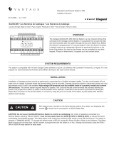
36V stations have a symbol on the Serial Number
sticker. Any station, not displaying this symbol, ,
should not be connected to a 36Volt Station Bus.
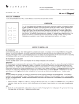
The Power Station Booster is a single load dimmer station able to handle a larger than normal 1oad.
The station installs in a 2-gang wall-box or in Wattstopper’s LCAP series enclosures. Faceplate
covers are available in Almond, Black, Brown, Ivory and White for 2-gang wall-box enclosures.
Wattstopper/Vantage
®
Power Station Booster
Installation Instructions
IS-0625 Rev. 2
STPSRW101 (201) / STPERW101 (201)
Country of Origin: Made in China
OVERVIEW
SPECIFICATIONS
Description Specication
Dimensions, HWD 4.34” x 4.25” x 2.5” (110.2mm x 107.9mm x 63.5mm)
Dimensions, Faceplate 4.75” square (120.6mm square)
Weight 14.4oz. (407g)
Voltage See Load Specications table
Load Types See Load Specications table
Number of Loads 1
Status Indicator Microprocessor Status
Station Wiring Conguration Daisy-chain / Star / Branch
*Station Bus Connection 24V / 36V Station Bus
Station Bus Wiring 2 Conductor, 16AWG / 1.31mm2, twisted, non-shielded, <30pF per foot.
Separate a minimum of 12” / 30.5cm from other parallel communication
and/or high-voltage runs
Station Equivalent InFusion 0.35W on IC-24 / 0.55W on IC-36
Station Equivalent QLink 1 Station
Cooling Convection
Ambient Operating Temperature 32 - 95°F ( 0 - 35°C)
Ambient Operating Humidity 5 - 95% non-condensing
UL and CUL Listed Yes
CAUTION
SYSTEM REQUIREMENTS
All four station types are compatible with InFusion Systems. For new projects it is recommended that rmware and software be kept
to the most current release.

2
IS-0625 – Rev. 2
LOAD SPECIFICATIONS
INSTALLATION
Standard Dimmer Electronic Dimmer
Model
STPSRW101 STPSRW201 STPERW101 STPERW201
Load Types
Forward Phase Only - Minimum Load 15W Reverse Phase Only - Minimum Load 5W
Incandescent
Magnetic low-voltage*
LED
Incandescent
Magnetic low-voltage*
LED
Incandescent
Electronic lighting*
LED
Incandescent
Electronic lighting*
LED
Voltage/Frequency 120VAC, 50/60Hz 220-277VAC, 50/60Hz 120VAC, 50/60Hz 220-277VAC, 50/60Hz
Maximum Standard Load 16A, 1920W@120V 16A, 3520W@220V
16A, 4432W@277V
8A, 960W@120V 4.5A, 990W@220V
3.5A, 90W@277V
Maximum *MLV Load 1000VA @ 120V 2000V A@2 77V NA NA
Maximum LED Load
(see LED Dimming)
3.2AMP, 384W@120V 3.2A, 704W@220V
3.2A, 886.4W@277V
4.8A, 576W@120V 2.7A, 594W@220V
2.1A, 582W@277V
Installation of these products should be performed or supervised by a Certied Installer. Turn the circuit breaker off and make sure no
voltage is present before installing the Power Station Dimmer. Damage caused by failure to disconnect power may void warranty and
is a risk to the installer. Connect control wires for Station Bus stand-alone control or the ScenePoint dimmer station scenario. Connect
the wires as shown in the diagram (Black to LINE, White to NEUTRAL, Red to LOAD, Green to structure’s safety GROUND). Before
turning the circuit breaker on, check to see that all connections are correct (In particular, check to see that the correct wires have
been connected to “Line In” and “Load Out”).
The booster station may be controlled using one of the two installation congurations below. NOTE: Never connect using both
methods in the same installation.
1. As a stand alone dimmer: The booster is connected to and controlled through the Station Bus, acting as a stand alone, high
power, single station dimmer. -OR-
2. As a power booster for a ScenePoint Dimmer Station, Module Load, or LMRC-22x: The dimmed output from a dimmer station
or dimmer module is connected to the booster and acts as a control line. A separate line feed is attached to the booster and the load
is connected to the output. In short, the dimmer station or dimmer module controls the dim level, while the booster handles the power.
NOTE: Only connect one Power Station Booster to a dimmed load, using this method.
To reduce the risk of overheating and possible damage to other equipment, do not install to control a
receptacle. Any motor or appliance connected to a Power Station Booster requiring “RELAY MODE” must be programmed to relay
mode through software rst. The Power Station is shipped in “DIMMING MODE”. To change the default mode to RELAY change the
Power Prole to Relay in the Software. The Relay Mode change will not take place until the Power Station is on line and the system
is programmed.
With this station’s dimensions most standard back boxes that have the receiving threads for the station mounting screw inside the
box will be adequate. Most back boxes where the receiving threads are outside the box will be too small. Test back boxes for proper
t before installing.
BACK BOX / MUD RING DIMENSIONS
With this station’s dimensions most standard back boxes that have the receiving threads for the station mounting screw inside the
box will be adequate. Most back boxes where the receiving threads are outside the box will be too small. Test back boxes for proper
t before installing. If mud rings are specied on a job it is important to test the mud rings for proper t. Two gang mud rings, in
particular, run substantially smaller than back boxes and some brands are not large enough for the station. The only solution is to test
the t rst.
DEFAULT MODE
The Power Station has a default mode that operates without programming or being connected to the InFusion System. If the Power
Station has been programmed but communication with the controller is lost the station will revert to default operation. The button on
the front of the station acts as follows (see next page):
Back Box Minimum Back Box Dimension
2-Gang Back Box 2.80”h x 3.60”w x 2.5”d
CAUTION

3
IS-0625 – Rev. 2
First select the room, then click on Vantage Objects in the Object Explorer and expand Stations, WireLink. From the list of
stations double click on the Power Station to place it in the room. In the Object Editor name the station, select the correct model and
make sure it is on the correct Station Bus port.
CONFIGURING
If using the conguration install method number “2” above, the station should not be congured. For method “1” above, the serial
number may be manually typed in the project le. Traditional conguration: When the Power Station is rst connected to the
Station Bus, the diagnostic LED will blink twice followed by a pause. This means the Power Station is connected correctly but is not
congured. It is congured like any other station. From Design Center, click on the Congure Stations button on the toolbar. To nish,
press the congure button on the front of the station. Once congured the diagnostic LED will blink evenly.
DIAGNOSTIC INFORMATION
The Diagnostic LED blinks 1 time evenly or 2, 3, 4, or 5 blinks followed by a pause.
One Even Blink: The Power Station is operating correctly and is congured.
Two Blinks: The Power Station is operating correctly but is not congured.
Three Blinks: The Power Station is not communicating with the Main Controller. Check the Station Bus connection.
Four Blinks: Factory problem. Please contact the factory.
Five Blinks: The Power Station is waiting to be congured.
PROPER TORQUE and WIRE
RESET
The power booster station operates as a standalone or as a high power load on the system. To reset, turn OFF power to LINE. With
the power OFF, hold in the Congure/Toggle button on the front while power is restored to LINE. Continue holding the button in for
about two (2) seconds to make sure the station reset happens.
NOTE: If the Station Load was changed to RELAY this Process will change it back to DIM. Make sure it is back on line with the Main
Controller before testing button or load operation.
DEFAULT BUTTON OPERATION
Action Load Operation
Single Press The load toggles between off and the learned level. The turn on ramp
time is 1.5 seconds and the turn off fade time is 5 seconds.
Double Press The load ramps to 100% in 1.5 seconds. The second press must be
within 1 second of the rst press.
Press and Hold After a one second delay the load will ramp in the opposite direction
from the last press and hold. If the load reaches 0 or 100% it will reverse
direction. When the button is released the current load level will be saved
as the new learned level for that button. The cycle time is 5 seconds from
0-100%.
Relay Mode The load turns on with the rst press and release and OFF with the
second press and release.
SETUP IN DESIGN CENTER
Connector Torque Wire Range
LINE/LOAD WIRING 20 INCH POUNDS 14-10 AWG (Must match breaker wire gauge)
LED DIMMING
• Legrand is leading the way in LED lighting control through innovations of new hardware and software products;
however, industry standards are still undened for dimming LED lamps and xtures. Dimming performance of
LED lighting cannot be guaranteed, even when applying the correct dimming technology specied by the LED
manufacturer. While Legrand may be consulted when performance issues are present, Legrand will not be liable for
on-site performance issues.
• There are many factors that may contribute to unsatisfactory results within a specic installation, including, but not
limited to:
- Line noise originating from electrical equipment within the premises
- Line noise from the source (particularly with local generators or inverters)
- Interference between dimmed LED products
- Wiring conditions (i.e. shared neutrals, loose neutrals, incorrectly bonded neutral, or grounding issues)
- LED product variances, including:
• Unintended batch-related variances
• Product revisions

4
800.555.9891
www.legrand.us/wattstopper
IS-0625 – Rev. 2
© Copyright 2019 Legrand All Rights Reserved.
© Copyright 2019 Tous droits réservés Legrand.
© Copyright 2019 Legrand Todos los derechos reservados.
Wattstopper warranties its products to be free
of defects in materials and workmanship for a
period of five (5) years. There are no obligations
or liabilities on the part of Wattstopper for
consequential damages arising out of, or in
connection with, the use or performance of this
product or other indirect damages with respect
to loss of property, revenue or profit, or cost of
removal, installation or reinstallation.
Wattstopper garantit que ses produits sont
exempts de défauts de matériaux et de fabrication
pour une période de cinq (5) ans. Wattstopper
ne peut être tenu responsable de tout dommage
consécutif causé par ou lié à l’utilisation ou
à la performance de ce produit ou tout autre
dommage indirect lié à la perte de propriété, de
revenus, ou de profits, ou aux coûts d’enlèvement,
d’installation ou de réinstallation.
Wattstopper garantiza que sus productos
están libres de defectos en materiales y mano
de obra por un período de cinco (5) años. No
existen obligaciones ni responsabilidades por
parte de Wattstopper por daños consecuentes
que se deriven o estén relacionados con el
uso o el rendimiento de este producto u otros
daños indirectos con respecto a la pérdida
de propiedad, renta o ganancias, o al costo
de extracción, instalación o reinstalación.
WARRANTY INFORMATION INFORMATIONS RELATIVES À LA GARANTIE INFORMACIÓN DE LA GARANTÍA
MULTI-VIEW LINE DRAWING
WIRING
LINE / HOT
LOAD
DIM
CONTROL
NEUTRAL
CAUTION:
USE COPPER WIRE ONLY RATED FOR AT LEAST 75°C
WARNING:
TURN OFF POWER BEFORE MAKING SUPPLY CONNECTIONS
CLASS 2
UP
GND - Green Wire
Station
Bus
Control Option 1
Standalone Station Bus
Control Option 2
ScenePoint Dimmer Station/Module/
LMRC-22x
(neutral from dimmer station not needed)
LOAD and NEUTRAL
to Fixture
LINE and NEUTRAL
From Breaker
FRONT VIEW SIDE VIEW BACK VIEW
Configure and
Toggle Button
Status LED
LINE / HOT
LOAD
DIM
CONTROL
NEUTRAL
CAUTION:
USE COPPER WIRE ONLY RATED FOR AT LEAST 75°C
WARNING:
TURN OFF POWER BEFORE MAKING SUPPLY CONNECTIONS
CLASS 2
UP
GND - Green Wire
Station
Bus
4.34"
4.25"
4.75"
1.625"
2.5"
0.875”
/


