Page is loading ...

INSTALLATION AND PROGRAMMING GUIDE
1135 Series
Wireless Siren

1135 Series Installation and Programming Guide | Digital Monitoring Products 1
GET STARTED
The 1135 Series Wireless Siren provides up to 110decibels of annunciation. It includes a wall tamper, a cover tamper,
and a Survey LED.
Multiple sirens can be activated simultaneously by the panel using the Trip with Panel Bell option. This option allows
the siren to follow the panel bell output including the bell cuto time.
In addition to these features, the 1135E Wireless Siren communicates with the panel using 128‑bit AES encryption.
What’s Included
▶One 1135 Series Wireless Siren
▶Two 3.0V Lithium CR123 Batteries
▶Hardware Pack
What You’ll Need
▶5/64” (2.0mm) drill bit
▶#2 Phillips screwdriver
Procedure
To install an 1135 Series Siren, this guide walks you through these required steps:
1. Program the panel.
2. Install the batteries.
3. Select a location.
4. Mount the siren.
5. Test the siren.

1135 Series Installation and Programming Guide | Digital Monitoring Products 2
1 Program the Panel
To program the 1135 Series into the panel, select one of the following methods: Choose Method 1 to make the siren
a non‑standard output that follows the panel bell or Method 2 to make the siren a standard output.
A house code must be programmed in the panel’s SYSTEM OPTIONS before programming wireless devices.
Range is 1 ‑ 50.
For 1135E encrypted sirens to communicate with the panel, 1100 ENCRYPTION must be enabled and a passphrase
must be set in SYSTEM OPTIONS programming. An 1135E will operate as a standard 1135 wireless siren if
encryption is not enabled.
To enter panel programming, reset the panel and enter 6653 (PROG) at a keypad. After completing each of the
following steps, press CMD to advance to the next prompt. After you finish programming, go to STOP and press
CMD to save and exit the Programmer menu. For more information, refer to the appropriate panel programming
guide.
PANEL MODEL VALID OUTPUT NUMBERS
XR Series 450‑474 (slow) or 480‑499 (fast)
XT Series 31‑34 (slow) or 41‑44 (fast)
XTL Series 51‑54 (slow) or 61‑64 (fast)
Table 1: Valid Output Numbers by Panel Model
Method 1: Non-Standard Output (Follow Panel Bell Output)
1. Go to OUTPUT INFO (XR Series) or OUTPUT SETUP (XT and XTL Series).
2. At OUTPUT NO, enter the output number. Refer to Table 1.
3. At OUTPUT NAME, enter a descriptive name for the siren.
4. At SERIAL#, enter the 8‑digit device serial number.
5. At SUPRVSN TIME, enter the supervision time in minutes.
6. Ensure TRIP WITH PANEL BELL is set to YES (default).
7. Go to BELL OPTIONS and set the BELL CUTOFF. Range is 1 ‑ 15 minutes.
Enable Temporal 4 for CO Alarms (1135 Only)
Requires panel firmware Version 183 or higher with minimum device firmware Version 107 and Level 103 hardware.
In BELL OPTIONS, ensure CO TYPE is set to the default value4(Temporal4).
Method 2: Standard Output (Standalone)
1. Go to OUTPUT INFO (XR Series) or OUTPUT SETUP (XT and XTL Series).
2. At OUTPUT NO, enter the output number. Refer to Table 1.
3. At OUTPUT NAME, enter a descriptive name for the siren.
4. At SERIAL#, enter the 8‑digit device serial number.
5. At SUPRVSN TIME, enter the supervision time in minutes.
6. At TRIP WITH PANEL BELL, select NO.
2 Install the Batteries
Observe polarity and install both CR123 batteries. For the battery holder location, refer to Figure 1.

1135 Series Installation and Programming Guide | Digital Monitoring Products 3
Select a Location
The 1135 provides a Survey LED capability to allow one
person to confirm communication with the wireless
receiver or panel while the cover is removed.
1. With the cover removed, hold the siren in the
desired location.
2. Press the tamper switch to send data to the panel
and determine if communication is confirmed or
faulty.
Confirmed: If communication is confirmed, for each
press or release of the tamper switch, the LED blinks
immediately on and immediately o. Repeat this test
to confirm five separate consecutive LED blinks. Any
indication otherwise means proper communication
has not been established.
Faulty: If communication is faulty, the LED remains
on for about 8 seconds or flashes multiple times in
quick succession. Relocate the siren or receiver until
the LED confirms clear communication.
Note: Operating the siren in extreme hot or cold
environments reduces battery life.
3
4
Mount the Siren
Mount the siren in a secure location where it is protected from the environment.
The 1135 siren is equipped with a case and wall tamper. When the housing cover is removed, the case tamper
activates and the 1135 sends a tamper trouble to the panel.
A two‑position header is provided to disable the wall tamper. Refer to Figure 1. To disable the wall tamper, place
the jumper over both header pins.
Without Wall Tamper
1. Remove the two locking screws from the housing, then lift o the cover.
2. Ax the siren to the mounting surface:
a. If using screws, thread the supplied #6 screws through the mounting holes and secure the siren to the
surface.
b. If using double‑sided tape, place the tape on the housing base (the side with mounting holes). Remove
the backing from the tape. Holding the sides of the housing, press the siren onto the mounting surface.
3. Place the jumper over both header pins to disable the wall tamper.
4. Place the cover back onto the base, then reinsert and secure the two locking screws.
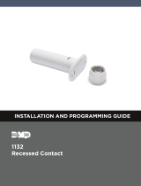
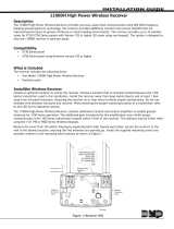
Figure 1: 1135 Details
A
B
C
Mounting Holes
PCB Snaps
Batteries
E
F
G
DSound Level
Wall Tamper
Case Tamper Switch
Survey LED
TAMPER
SWITCH
SOUNDER
C
A
AA
A
AA
F
D
B
B
C
B
B
G
E
100 dB
WALL
TAMPR DIS

1135 Series Installation and Programming Guide | Digital Monitoring Products 4
5
Test the Siren
After the sirenhas been installed, test to confirm that it is communicating reliably with the panel. Use the Tech
APP™ or Dealer Admin™ to perform a Wireless Check‑in Test on the system. To perform a Wireless Check‑in Test
from a keypad that is connected to the panel, complete the following steps:
At the keypad, enter 8144 (WALK) and select WLS. If the transmitter fails to check in at the keypad, ensure that it
is wired properly and check for sources of interference such as metal objects and electronic equipment.
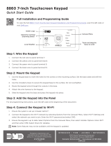
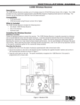
With Wall Tamper
When installing the siren with the wall tamper, refer to Figure 2.
1. Remove the two locking screws from the housing, then lift o the cover.
2. Press the top PCB snaps upward to release the PCB, slide it out of the
bottom snaps, then remove it from the housing.
3. Thread one of the supplied #6 screws through the top tamper hole and the
other through the top mounting hole, then secure the siren to the surface.
4. Snap the PCB back into the housing attached to the wall. Place the cover
back onto the base, then reinsert and secure the two locking screws.
Figure 2: Wall Tamper
Installation
ADDITIONAL INFORMATION
Requirements for Listed Installations
▶The siren cannot be mounted with double‑sided tape
▶UL 1610 Central station Burglar Alarm Units: Must be installed With Wall Tamper
▶UL 985 Household Fire Warning System: Must Enable Temporal 4 for CO Alarms
Disable the Wall Tamper
A two‑position header is provided to disable the wall tamper. Refer to Figure 1. To disable the wall tamper, place
the jumper over both header pins.
Change the Sound Level
The siren is equipped with a 100/110 decibel (dB) jumper and a two‑position header to change the decibel output.
The siren is shipped at the 110dB output level with the jumper placed on one pin for storage. If the 100dB setting
is required, place the jumper over both header pins. Refer to Figure 1.
Silence the Sounder
The following panel operations can silence the sounder:
▶BELL OUTPUT (XR150/XR550only)—Program the output in BELL OUTPUT so the sounder turns o at the
BELL CUTOFF time if less than fifteen minutes
▶Disarming—Program the output in ALARM ACTION for the zone that will be disarmed, then set the action
to STEADY
▶OUTPUTS ON/OFF—In the User Menu, select OUTPUTS ON/OFF. Enter the output number and choose
OFF
▶Output followszone condition—Program the output in ALARM ACTION and set the action to FOLLOW.
When thetransmitterzone restores, the output is turned o

1135 Series Installation and Programming Guide | Digital Monitoring Products 5
Status List
For XR Series systems to display wireless output troubles at a keypad, that keypad’s address must be entered in
STATUS LIST > AUX 1 ZONES (Auxiliary 1 Zones).
Output Response Time
Outputs operate with a 3‑second response time when used with the 1135‑W.
Battery Life Expectancy
Battery life expectancy for is 3years when the siren is operated for 5minutes once a month. DMP wireless equipment
uses two‑way communication to extend battery life. To extend battery life further, operate the siren infrequently and
extend supervision time in panel programming. Multiple on/o siren operations and extreme hot or cold environments
reduce battery life.
Replace the Battery
1. Remove the locking screws from the top and bottom of the siren housing.
2. Lift the cover from the bottom to remove it from the base.
3. Remove the old batteries and dispose of them properly. Always replace both batteries at the same time.
4. Install the two CR123 batteries and press into place. Refer to Figure 1 for battery locations.
5. Place the cover back onto the base and secure the housing using the locking screws.
Sensor Reset to Clear LOBAT
Once the battery is replaced, a sensor reset is required at the keypad to clear the LOBAT message. On an LCD keypad,
press and hold 2for two seconds. On a graphic touchscreen keypad, press RESET. Enter your user code, if required.
The keypad displays SENSORS OFF followed by SENSORS ON.
SPECIFICATIONS
Battery Life Expectancy 3 years
Battery Type 3.0 V lithium CR123
Internal Sounder Type Y
Tone Output 100 dBA at 3 ft (1 m)
Frequency Range 905 ‑ 924 MHz
Operating Temperature 32°F to 120°F (0°C to 49°C)
Relative Humidity 85% at 86°F (30°C)
Housing Material Flame retardant ABS
Weight 0.5 lbs (0.23 kg)
Dimensions 4.5 L x 4.5 W x 1.25 H in
(11.4 L x 11.4 W x 3.2 H cm)
PATENTS
▶U.S. Patent No. 7,239,236
CERTIFICATIONS
▶FCC Part 15 ID: CCKPC0123R8
▶Industry Canada: 5251A‑PC0123R8

18205
Designed, engineered, and
manufactured in Springfield, MO
using U.S. and global components.
LT-1106 1.06 22184
INTRUSION • FIRE • ACCESS • NETWORKS
2500 North Partnership Boulevard
Springfield, Missouri 65803-8877
800.641.4282 | DMP.com
© 2022
Underwriters Laboratory (UL) Listed
ANSI/UL 1023 Household Burglar Alarm System Units
ANSI/UL 1610 Central Station Burglar Alarm Units
ANSI/UL 985 Household Fire Warning System
FCC Information
This device complies with Part 15 of the FCC Rules. Operation is subject to the following two conditions:
1. This device may not cause harmful interference, and
2. This device must accept any interference received, including interference that may cause undesired operation.
Changes or modifications made by the user and not expressly approved by the party responsible for compliance could void the user’s authority to
operate the equipment.
Note: This equipment has been tested and found to comply with the limits for a Class B digital device, pursuant to part 15 of the FCC Rules. These
limits are designed to provide reasonable protection against harmful interference in a residential installation. This equipment generates, uses and
can radiate radio frequency energy and, if not installed and used in accordance with the instructions, may cause harmful interference to radio
communications. However, there is no guarantee that interference will not occur in a particular installation. If this equipment does cause harmful
interference to radio or television reception, which can be determined by turning the equipment o and on, the user is encouraged to try to correct
the interference by one or more of the following measures:
• Reorient or relocate the receiving antenna.
• Increase the separation between the equipment and receiver.
• Connect the equipment into an outlet on a circuit dierent from that to which the receiver is connected.
• Consult the dealer or an experienced radio/TV technician for help.
Industry Canada Information
This device complies with Industry Canada License‑exempt RSS standard(s). Operation is subject to the following two conditions:
1. This device may not cause interference, and
2. This device must accept any interference, including interference that may cause undesired operation of the device.
Le présent appareil est conforme aux CNR d’Industrie Canada applicables aux appareils radio exempts de licence. L’exploitation est autorisée aux deux
conditions suivantes:
1. l’appareil ne doit pas produire de brouillage, et
2. l’utilisateur de l’appareil doit accepter tout brouillage radioélectrique subi, même si le brouillage est susceptible d’en compromettre le
fonctionnement.
/