Page is loading ...

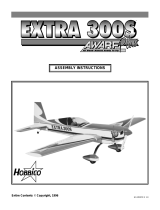
STARFIRE 40
Almost-ready-to-fly Radio Controlled Model Airplane
• Superior quality in an Almost-Ready-to-Fly model
• 80% complete out of the box - No Sanding, Painting, or Finishing required.
• Beautiful sporty appearance.
• Super acrobatic aircraft for experienced pilots
• All wood construction with sheeted wings
• Fuel Tank, Spinner, Wheels, Landing Gear, Engine Mount, and Hardware are included.
WINGSPAN: 55 1/2 in.
LENGTH: 49 3/4 in.
WING AREA: 534sq.in.
WEIGHT: 5 1/2 pounds
ENTIRE CONTENTS © 1991, HOBBICO , INC. V1.0
RADIO: 4 channel (not included)
ENGINE: .40 Performance 2-cycle (not included)
or .61-.91 4-cycle (not included)
ACCESSORIES: Standard field equipment (not included)

IMPORTANT: BEFORE YOU BEGIN.
Congratulations on your choice of an AWARF kit. BEFORE you begin assembly, carefully look through the box and
thoroughly read the instruction manual. Check the parts list against the items in the box to be sure you have everything that is
on the parts list. Although we have taken great pains to simplify the building process, there are no shortcuts to safety. These
instructions are your guide to safe and successful flying.
Only after you are thoroughly familiar with the construction process should you proceed with assembly. Remember! Under
no circumstances will a dealer accept a kit back for return if assembly has already begun.
If the Starfire is not quite what you expected, return it to your dealer in New and Unused condition. However, we think you
will agree with us that the Starfire kit is one of the finest models of its type and will offer you many hours of enjoyment.
BEFORE ASSEMBLY
CONSTRUCTION HINTS:
1. IMPORTANT! Trial fit each part before gluing.
Be certain that the parts fit properly.
2. Use PlastiZap or a thin type Cyanoacrylate glue for
installing the plastic parts. Do not use too much, as it
may run and spoil the appearance.
3. It is best to use 30 minute (or longer) epoxy for
assembly. This
will
allow time to position
the
parts
before the epoxy cures.
4. Before assembly, place your radio system on charge.
5. There is a metric ruler on page 3 to aid in finding the
correct screw or part sizes.
ADDITIONAL ITEMS
The following items are needed for completing the
Starfire kit:
Medium Fuel Tubing (12") .................................................1
.40 Sized 2-Cycle Engine....................................................1
OR
.61 - .70 Sized 4-Cycle Engine............................................1
4 - Channel Radio System.................................................1
Pacer PlastiZap CA Glue....................................................1
Goldberg #481 Foam Rubber .............................................1
Hobbico (HCAR3950) 30-Minute Epoxy............................1
Silicone Sealer.....................................................................1
Dubro 121 E-Z Connects (Optional)...................................2
Hobbico (HCAR3760)Threadlock...................................... 1
Dubro 340 in line Fuel Filter.............................................1
Propeller (Size depends on the engine) .............................1
Starter
12 V Battery
Glow Driver
Standard field equipment is required for running the engine:
Starter, 12V Battery, Hot Shot Glow Plug Driver and compatible
glow engine fuel.
O.S. 70 Surpass
4-cycle
O.S. .40 SF
2-cycle
Glow Fuel
l See Engine s
Recommendations)
REQUIRED FOR RUNNING THE ENGINE
TOOLS
You will need the following basic tools to assemble the kit. Hobby
knife. Phillips screwdriver (small and medium), needle nose pliers,
drill, drill bits, sanding block, ruler, and string.
A quality brand engine will be needed. We recommend the O.S.
.40 SF 2-Cycle engine or the O.S. 70 Surpass 4-cycle engine.
RADIO SYSTEM
A four-channel radio control system with 4 servos is required for
the Starfire 40.
2.

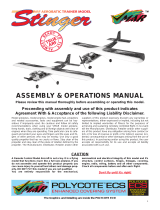
PARTS LIST
Before assembly, match the parts in the photo on this page with
the parts in the kit. Check off each part as they are located. If
any parts are missing or damaged, consult your hobby dealer.
( ) 1 Fuselage.........................1
( ) 2 Right Wing.....................1
( ) 3 Left Wing.......................1
( ) 4 7mm Dowel Rod ............2
( ) 5 Wing Joiner ...................1
( ) 6 Reinforcing Blocks ........2
( ) 7 Wing Center Cover........1
( ) 8 Hinges............................13
( ) 9 Ailerons..........................2
( ) 10 Aileron Servo Tray........1
( ) 11 Wing Mounting Blocks..3
( )12 Blind Nuts.....................2
( ) 13 4 x 30mm Wing Screws.2
( ) 14 4mm Washers ................2
( ) 15 0-Rings..........................2
( ) 16 Main Gear Struts..........2
( ) 17 Plastic Tree....................1
( ) 18 3 x 15mm S/T Screws....8
( ) 19 Bellcrank.......................1
( ) 20 3 x 8mm Screw ..............1
( ) 21 Front Gear Strut...........!
( ) 22 White Tube ....................2
( ) 23 450mm Rod....................2
( ) 24 Wheel Collars ...............7
( ) 25 3 x 5mm Screws ............7
( ) 26 Wheels ...........................3
( ) 27 Mounting Plates............2
( ) 28 3 x 15mm Screws ..........8
( ) 29 Lockwashers..................8
( ) 30 3mm Nuts......................4
( ) 31 Wing Pad .......................1
( ) 32 Cowl Decal..................... 1
( ) 33 Fuel Tank ......................1
( ) 34 Rubber Cap....................1
( ) 35 Fuel Tank Clunk ...........1
( ) 36 Fuel Line .......................1
( ) 37 Fuel Pipes......................3
( ) 38 3 x 18mm S/T Screw .....1
( ) 39 Large Disc......................1
( ) 40 Small Disc......................1
( ) 41 Neoprene Ring...............1
( ) 42 Clevis Retaining Tube...l
( ) 43 Bent Rods ......................2
( ) 44 Short Rods.....................2
( ) 45 Long Rods......................3
( ) 46 Wooden Push Rods........2
( ) 47 Shrink Tubing ...............4
( ) 48 Push Rod Exits..............3
( ) 49 Horizontal Stabilizer.....!
( ) 50 Vertical Stabilizer .........1
( ) 51 Rudder............................1
( ) 52 Elevators.........................2
( ) 53 Turtle Deck....................1
( ) 54 Spinner...........................1
( ) 55 2 x 20mm Screws ..........6
( ) 56 Right Cowl.....................1
( ) 57 Left Cowl.......................1
( ) 58 Canopy...........................1
( ) 59 Red Striping Decal........ 1
( ) 60 Side Decal......................2
3.

WING ASSEMBLY
3 Trial fit the 7mm dowel rods into the holes and butt them up
against the front spar They should be positioned straight in and
parallel to the wing root Once satisfied with the fit, epoxy them
in place using slow cure epoxy.
1. On both wing halves, make a mark exactly 1 from the wing root
on the leading edge
4. Next, using a sanding block sand the wing roots of both wing
halves to ensure that they are perfectly flat Be careful not to
change the dihedral angle of the root
2 Drill a 7mm hole at each mark Make sure that you drill straight
in at the center of the mark parallel to the wing root
5 Trim each wing half for the aileron servo as shown It's much
easier to do this now than after the wing is assembled
4.

IMPORTANT!
The
following
two
steps
are
critical
in
the
assembly
of this kit. If they are not done correctly, wing failure could result Be
sure to use plenty of slow cure (30 min) epoxy
6
Check
the
wing
joiner
to
find
the
angled sides
Place
the
joiner on
a flat surface and rock until you have identified the two angled
sides
The
angled
face
side
should
point
forward
and
the
angled
narrow side should face down for proper dihedral Using one of
the wing panels trial fit the wing joiner and check for proper
alignment Position
the
joiner so
it
will
be
centered
when
the
two
wing halves are joined together Once satisfied with the fit, glue
the joiner in place using slow cure epoxy Let cure
7 Trial fit the two halves together and line up the leading and
trailing edges Check for a good gap-free fit Sand if needed
Once satisfied, glue the two wing halves together using slow cure
epoxy You can tape the wing halves together to hold them tight
while the glue cures
9 Install the wing center cover using Plastizap CA Glue Wipe
off
any excess glue
immediately
Next on
the
front
of the
cover glue the wing pad on as shown using Plaslizap CA Glue
10 Install the six aileron hinges into the slots at the trailing edge of
the wing using epoxy Only a small amount of glue is needed
here
Use too much and it
will
seep
into
the
hinge
causing
it to
lock up You may wish to apply a small amount of vasiline to the
hinge joint to
pr
otect it against
epoxy
If
any
glue
does
set
up
into
the joint, remove it immediately using a soft cloth and rubbing
alcohol.
8 Line up the reinforcement blocks as shown so that the sides angle
in Remove the wing covering underneath the blocks Next, glue
the blocks to the wing using epoxy
11 Apply epoxy to the contiol rods and in the control rod slots of the
ailerons Next put a small amount of epoxy onto the the hinges
and install both ailerons
5.

12. Check the ailerons for smooth operation. By exercising the
ailerons after the glue is cured, you can loosen any of the stiffness
that might have been created by glue seeping into the hinges.
15. Glue the three wing mounting blocks together using slow cure
epoxy. Center the three blocks together by lining up the holes.
The larger block should be at the bottom.
13. Align the aileron servo tray on the wing and trace around it using
a ball point pen. Remove the covering material that was outlined
underneath the tray.
16. Install the blind nuts to the larger side of the mounting block.
These can easily be pressed in with a pair of pliers.
14. Glue the tray to the wing using slow cure epoxy.
17.
Epoxy
the
mounting block
inside
the
fuselage.
It
is
critical
that
this
joint
is
solid.
Use plenty
of
epoxy.
Let
cure.
6.

18. Thread the wing screws into the blocks so that the heads are 3/8"
above the block. Apply ink or paint to the heads of the screws.
Proceed with the next step immediately before the ink or paint
dries.
21. Place the two 4mm washers onto the 4 x 30mm screws and push
them through the wing from the bottom side. Next, slide the
rubber 0-rings onto the screws.
19. Place the wing onto the fuselage as shown. Put the front in first
by inserting the dowel rods in the holes. It may be necessary to
round the tips of the dowel rods and bevel the holes in order to
allow easier installation. Once in place, center and lower the
back onto the screw heads. This will mark where you need to
drill.
22. Trial fit the wing onto the fuselage. Check for a solid fit then
remove.
LANDING GEAR INSTALLATION
20. Drill two 3/16" holes 90° from the bottom wing surface using the
paint marks as a guide.
7.

1. Feel along the front edge of the blue stripe until you find the two
slots under the covering, trim out the covering over the slots.
4. Temporarily install the strut and mark the bottom of the fuselage
for the installation of the control rod Mark the hole about 1"
from the firewall and 7/8 from the left bide of the fuselage.
2. Install the two main gear struts into the wing and attach using
the plastic retaining straps and 3 x 10mm self-tapping screws.
You may with to drill eight 1/16" holes to prevent the wood from
splitting when installing the screws.
5. Drill a 1/8" hole angling back at the mark.
Attach the bellcrank onto the front gear strut and secure with a
3 x 8mm screw onto the flat.
6. Epoxy in the white tube so that it only protrudes 1/8" out of the
fuselage Make sure all exposed wood around the tube is covered
with glue in order to seal against fuel.
8.

7. Make a Z-bend on one end of the 450mm control rod. Install the
front strut with the rod and secure with a collar and a 3 x 5mm
screw.
1. Temporarily install the two mounting plates onto the mount so
the engine will angle slightly to the right for 2 degrees. Tighten
the screws only until they seat so that you can still move the
plates.
8. Install the wheels using a wheel collar on each side of the wheel.
Fasten the collars with 3 x 5mm screws.
2. Set the engine on the mounting plates so that the center line of
the engine is in line with the center of the engine mount. Make
sure that the engine has a slight right thrust angle of 1 or 2
degrees and that the front of the drive washer on the engine is
4-5/8" from the firewall Next, squeeze the plates against the
engine and mark the mounting holes on the plates.
Engine Installation
9
3. Remove the plates and drill four 1/8" holes at the marks.
Carefully remove off any burrs with a hobby knife.

4. Mount the engine to the mounting plates using four 3 x 15mm
screws, four lock washers, and four 3mm nuts as shown. Note:
Use thread locking compound on the screws and nuts to
prevent them from loosening under vibration.
7. Install the throttle control rod on the throttle arm of the engine.
5. Epoxy the white tube into the fuselage so that it sticks out I".
8. Slide the throttle control rod into the white tube and attach the
engine to the mount. Use four 3 x 15mm screws and four lock
washers to hold the engine in place. Note: Use thread locking
compound on the screws.
Fuel tank Assembly
6. Make a Z-bend in the 450mm rod as shown
10.

1. Install one of the long and one of the short fuel pipes through the
rubber cap. Center the pipes in the cap and place the two plastic
discs onto each side. The large one should be on the outside. The
flange on the small one should face the rubber cap. Put the 3 x
18mm self-tapping screw in the center hole from the large end
and tighten it only a couple of turns into the small disc.
4. Attach the completed fuel tank cap to the tank. Make sure that
the bent pipe is pointing to the top. Slide the cap on until the lip
on the fuel tank is in the groove of the cap. Then tighten the
screw. Check to make sure the clunk is free to swing at the
bottom of the tank.
5. Glue the neoprene ring to the tank with silicone sealer. Attach
two pieces of fuel tubing (5" long) to each of the pipes.
Attach the fuel line to the short fuel pipe and attach the clunk to
the other end. Adjust the length of the line so that the clunk
reaches nearly to the rear of the tank but not up against it once
installed.
Carefully bend the other fuel pipe so it will just touch the inside
top of the fuel tank
6. Put a bead of silicone sealer on the ring. Proceed with the next
step before the sealer dries.
11.

8. Install the completed tank into the fuselage. Route the fuel
tubing through the hole and push the tank cap through until
seated. Attach the carburetor line (bottom one) to the engine.
Shorten as needed.
Radio Installation
2. Screw the aileron horns onto the aileron arms. Make sure you use
the two horns with the larger holes.
3. Cut five 3/16" pieces of the clevis retaining tubing. You will use
two now and three later.
1. Check the fit of your aileron servo in the aileron servo tray. You
may have to trim away some of the servo tray for a good fit.
Install the grommets onto the servo and mount using the screws
provided with the radio system.
4. Screw two snap clevises halfway up the threads on the shorter
control rods. Next, slide two of the 3/16" clevis retaining tubes
onto the rods.
12.

5. Attach the clevises to the aileron horns and slide on the retaining
tubes. After checking the neutral position of the aileron servo
and ailerons, put a mark on the push rods (scratching with a
hobby knife) where the servo arm holes line up. Be sure the
ailerons are in there neutral position.
8. Connect the aileron servo to the receiver and check the movement
of the ailerons. Make sure that both ailerons are neutral when
the servo is neutral. Adjust the clevises as needed.
6. At each mark, bend the pushrods at a right angle. Next, cut off
the push rods 6mm from the bend.
9. Install the three remaining servos into the tray using the
grommets and screws provided with the radio system. Be sure
that the servos are positioned as shown. You may have to trim
the tray slightly for a perfect fit.
7. Attach the rods to the servo arm using the rod clevis. Install the
clevis from the underside of the servo horn then snap onto the
rod.
10. Install the switch into the tray. You will have to drill the two
mounting holes depending on the switch. For a cleaner look,
install the Dubro #203 Kwik-Switch mount.
13.

11. Bend the three long rods as shown for the elevator and rudder.
Note: the pre-bent rods will be used later in step 13.
14. Next, do the same with the rudder push rod. Make sure that each
rod fits in the groove Now slide the four pieces of shrink tubing
over the ends of the wooden rods and shrink them with a heat
gun or lighter To ensure durability, place a drop or two of
Cyanoacrylate glue on the edges of the shrink tubing
12 Drill a 1/16" hole 1 1/2" from the ends (2 holes 1/16" apart on one
end of one rod) of both wood push rods With a hobby knife,
carefully cut straight grooves from the holes to the ends Only
cut a groove on one side of each end, except for the end of the rod
with two holes. For this end, make a groove on both sides.
15. Trim out the three push rod exits at the tail and insert the
rudder and elevator pushrods into the fuselage from the front. It
may be necessary to bend the rods slightly for a perfect fit.
13. Assemble the elevator pushrod as shown. Place the two elevator
rods into the double grooved end of the rod Next, place one of
the short (pre-bend) rods into the other end.
16. Using PlastiZap, glue the three plastic push rod exits to the
fuselage Check to make sure that the rods will easily move in
and out with no resistance. You may have to bend the rods
slightly for perfect fit
14.

17. Slide the throttle rod through an E-Z Connector and attach to the
servo arm. With the throttle at low position, pull back the rod
and tighten the screw on the connector. Plug the throttle servo
into the receiver and check for proper operation.
1. Trim out the covering and the wood piece at the tail of the plane.
18.
Slide the nose wheel rod through an E-Z Connector and attach to
the servo arm. With the rudder servo at center position, center
the nose wheel straight and tighten the screw on the connector.
Plug the rudder servo into the receiver and check for proper
operation.
2. Temporarily install the wing. Next, place the horizontal
stabilizer in place. Visually inspect the wing and stabilizer to see
if they are parallel. If not, sand the higher side of the stabilizer
mount until the stabilizer is parallel. It is critical for proper
performance that these two surfaces are parallel. Take
extra time to ensure a correct fit.
Tail Assembly
15
3. Next, take a piece of string and attach it with a pin to the top
center of the fuselage. Make sure that the stabilizer is centered
and stretch the string to the corner of the elevator . Adjust the
positioning of the stabilizer so that both corners are the same
length when moving the string from side to side.

4. When the stabilizer is perfect, draw a line with a sharp pencil on
both sides top and bottom (4 lines total).
7. Measure the rear fuselage to find the center. Draw a line along
center.
5. Remove the covering between the lines using a hobby knife.
8. Apply slow cure epoxy to the line and the bottom of the vertical
fin and install the vertical fin. Line up the fin with the rear of
the fuselage and the center line. Temporarily install the turtle
deck as a guide for the fin. Check the fin using a 90° angle to
ensure that it is straight up and down. Let cure.
6. Using slow cure epoxy, glue the stabilizer in place applying glue
to the exposed wood areas. Recheck the alignment using the
string as done earlier in step 3. Wipe off any excess glue using a
soft cloth and rubbing alcohol.
9. Wrap the battery and receiver in foam and install. Place the
battery above the fuel tank and the receiver behind the fuel tank.
Make sure that the radio is hooked up correctly and that an
aileron extension is being used.
16.

10 Trial fit the turtle deck onto the fuselage and check for a good fit
Once satisfied with the fit attach the turtle deck to the fuselage
using Plastizap CA glue Be careful not to use to much glue
13 Glue on the control surfaces with slow cure epoxy and allow to
cure Check the operation of the elevator and the rudder to
ensure smooth performance If they seem stiff, continue to
exercise until they loosen up
11 Trial fit the rudder onto the vertical fin Notice where the bottom
hinge meets the fuselage and mark a spot in the fuselage where
the rudder hinge slot will need to be using a hobby knife
14 Position the control horns on the elevators and mark the holes for
each onto the surface
12 Using slow cure epoxy, glue the seven hinges into the elevator
halves and the rudder Do not use too much glue or you may glue
the hinge joint solid
15 Position the control horn on the rudder and mark the holes onto
this surface
17

16. Drill six 1/16" holes at the marks. Make sure to drill straight in
through to the other side and mount the three horns to the
surfaces with the 2 x 20mm screws. Pass the screws through the
horn, through the surface and finally thread them into the
backplates.
19. Align the control rods over the respective servo horns and make a
mark where they intersect. Make sure that the control surfaces
are in neutral (center position) before marking.
17. Slide one of the retaining tubes onto each rod. Screw on the
plastic snap clevises to the three push rods coming out of the
fuselage. Screw them on half way up the threads.
20. Next, make a 90° bend upwards at the mark and cut off the
excess so that there is only 6mm of rod after the bend.
18. Attach the respective control rods to each horn. Use the middle
hole of the horn. Make sure that both elevator surfaces are the
same.
You
will
have to adjust
the
clevises to equalize. Next,
slide
up the retaining tubes to lock the clevises.
21. Attach the rods to the servos using the rod clevises as shown in
the above picture. You may need to enlarge the holes in the
horns slightly for a good fit. Check to ensure that when right
rudder is given, the nose wheel also turns right. If not, simply
install the E-Z Connector on the other side of the servo arm.
18.

Cowl Installation
3 Position the cowl in place and drill two 2mm holes 1 1/2 apart on
each side and install the 2 5 x 10mm S/T screws to secure the
cowl in place Attach the muffler and pressure line
1 Lightly sand the flanges on the left and right cowl edges This
will allow the glue to adhere better to the plastic Next hold or
tape the right side over the flange of the left side and glue
together along the inside beam with Plastizap CA glue Let cure
Final Assembly
2 Trial fit the cowl over the engine You will have to trim slightly
to allow clearance for the needle valve and muffler
1 Using Plastizap CA glue the canopy onto the fuselage and apply
the red striping decal around the perimeter
19

2. Next, carefully apply the decals to the cowl and the turtle deck.
Use the box lid for a reference.
5. Route the antenna through the hole in the fuselage and through
the hole in the tail. Use the plastic retainer and secure the wire
to the tail.
3. Install the spinner back plate, prop, prop washer, prop nut and
spinner with the 2.5 x 12mm S/T screws.
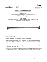
CENTER OF GRAVITY
4. Drill two 1/16" holes for the antenna. Position the first hole in
the left side of the fuselage and the second hole at the top of the
vertical fin.
Measure back 4-1/4" to 4-1/2" from the leading edge of
the wing next to the fuselage. Balance the plane at this
point. If not, add weight to the nose or the tail until it
balances perfectly. See below.
The center of gravity is a very important aspect of
setting up an airplane properly. It will control a large
part of what type of flying characteristics your plane
will have. If it is nose heavy the airplane will try to
dive, and the elevator will be sluggish to respond to
your control inputs. If the plane is tail heavy, it will be
very sensitive to the elevator and possibly
uncontrollable. The center of gravity should be checked
with the fuel tank empty and with radio equipment
installed. The plane should balance within 4-1/4" to
4-1/2" back from the leading edge at the fuselage. If it
does not balance within this range, add weight to the
nose or tail as you need to obtain the proper balance.
20.
/