Page is loading ...

ISD9 Data Sheet (NZ331) Page 1
Texmate, Inc. Tel. (760) 598-9899 • www.texmate.com
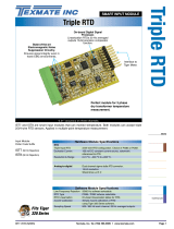
VOLTAGE & RESISTANCE SMART MODULE
Interface to
Tiger Meter.
On-board Digital
Signal Processor.
Optimized signal bandwidth
and output rate.
Attenuation Header.
1:100 selectable voltage
divider or DC current shunt.
Stable Voltage Reference
10 ppm / C
Constant Current Source.
Ratiometric referenced
5 mA excitation current.
Crystal
Controlled 50/60 Hz
Noise Rejection option.
Ultra-low Noise
16-bit A/D Convertor.
Approaches 19-bit
performance with additional
software filtering.
8-pin Input
Connector.
Voltage and resistance
inputs, voltage and
current excitation
outputs.
State-of-the-art
Electromagnetic Noise
Suppression Circuitry.
Ensures signal integrity under harsh
EMC environments.
Hardware Module Specifications
A/D Convertor Dual channel ultra-low noise 16-bit A/D
with effective 19-bit resolution in post processing software.
Input Sensitivity 0.08 µV/count maximum.
Zero Drift ± 40 nV/ °C typical.
Span Drift ± 5 ppm/ °C of full scale maximum.
Non-linearity ± 0.003% of full scale maximum.
Input Noise 160 µVp-p typical at 1 Hz output rate.
Voltage Reference + 2.5 V, 10 ppm.
Voltage Input Selection of ranges ± 25 mV to ± 2 V, 2.1 V common mode.
Attenuation Header 1:100 voltage ÷ for voltage inputs ≤ 60 V or
optional mA current shunt configuration.
Excitation Voltage + 24 V (50 mA) to drive external sensors.
Resistance Input Designed to measure voltage drop across small resistances
(typically ~10 Ω), +3 V common mode.
Resistance Resolution 1 mΩ (10 Ω load resistor).
Excitation current 5 mA constant current source to drive external resistor.
Ratiometrically referenced to A/D for precision
low-drift resistance measurement.
Software Module Features
Output Rates A choice of average response outputs, 1-20 Hz.
Gain Select 7 voltage ranges to optimize signal resolution.
Frequency Select 50 / 60 Hz noise rejection. Software selectable.
Initially designed to measure copper winding resistance to within fractions of an ohm and the surface
temperature using an infrared sensor. When coupled with the Tiger 320 Series operating system this
module, and its on-board current and voltage excitation outputs, satisfy OEMs wishing to accurately
measure a range of resistance and voltage/current signals.
The smart answer to precise resistance & voltage measurement
[50 Hz/60 Hz]
[60 Hz]
Fits Tiger 320 Series
Dual Smart
16-bit Precision
Volts DC
Resistance
INPUTS
ISD9 (50/60 Hz)
Input Module
Order Code Suffix

ISD9 Data Sheet (NZ331)
Page 2 Texmate, Inc. Tel. (760) 598-9899 • www.texmate.com
Programming Quick Start Guide
PIN 1
PIN 2
PIN 3
PIN 4
PIN 5
PIN 6
PIN 7
PIN 8
SIGNAL HI
EXTERNAL
TRANSDUCER
(Voltage output)
Resistance
Measurement
SIGNAL LOW
SUPPLY
GROUND
VOLT HI
VOLT LOW
VOLT EXC
EXC RTN
CURRENT EXC
RESISTANCE HI
RESISTANCE LOW
CURRENT RTN
318 A
mV
Programming Procedures
Connector Pinouts
Smart Setup Registers
The meter has three smart setup registers to configure all smart input modules.
ISD9 requires smart registers 1 and 2 to be configured. Because this is a dual input module , measuring voltage and resistance, independent sensor
inputs can be software selected for Tiger 320 Series meter channels 1, 2, 3, and 4. This module produces two output registers. One of these regis-
ters can be transferred to Channel 1 via Code 2, the same or another register to Channel 2 via Code 4, the same or another regi ster to Channel 3 via
Code 5, and the same or another register to Channel 4 via Code 6.
The following programming procedures cover all the steps required to configure smar t input module ISD9. Steps 1 to 5 describe how to select the line
frequency rejection, the voltage range, and the averaged output rate through smart setup register 1.
Steps 6to 9 describe how to select the resistance r ange through smart setup register 2.
Steps 10 to 19 describe how to select the output register for channels 1, 2, 3, or 4 as required.
Input Signal 1 CODE 2 SMART REGISTER 1 SETUP OUTPUT REGISTER MAP
Enter Code 2.
Select smart input module setup register 1.
This allows you to enter smart setup register 1 and
configure settings for input signal 1.
Select all rele vant settings
for input signal 1.The output register map
allows y ou to select a
specific output f or a
selected channel.
CH1
CH2
CH3
CH4
Input Signal 2 CODE 5 SMART REGISTER 2 SETUP
Enter Code 5.
Select smart input module setup register 2.
This allows you to enter smart setup register 2 and
configure settings for input signal 2.
Select all rele vant settings
for input signal 2.
Smart Setup Register – Operational Flow Diagram
SMART REGISTER 3 SETUP
Not required.
2
3
1
SIGNAL 1 VOLTAGE RANGE
0±±2 V
1±1 V
2±500 mV
3±250 mV
4±100 mV
5±50 mV
6±25 mV
7-
SECOND DIGIT
OUTPUT RATE
0 1 Hz averaged
1 5 Hz averaged
2 10 Hz averaged
3 20 Hz averaged
4-
5-
6-
7-
THIRD DIGIT
FIRST DIGIT
MEASUREMENT TASK
0 Voltage, Current
1 TC (3rd digit selects type of TC)
2 RTD 3-wire (3rd digit selects type
of RTD)
3 RTD 2- or 4-wire (3rd digit selects
type of RTD)
4 Frequency
5Period
6 Counter
7 Smart Input Module
SECOND DIGIT
0 -
1 60 Hz rejection
2 -
3 50 Hz rejection
FIRST DIGIT
This setting enters the smart register 1 code
setup menu.
This menu provides settings unique to smart
register 1 of the ISD9 input module.
Press the and buttons at the same time to enter the main programming mode.
P
Press the button.
This enters smart register 1 code setup menu.
P
Press the button twice to enter Code 2 for input signal 1 configuration settings. Set Code 2 to [X77].
P
OUTPUT REGISTER MAP
0 Averaged Signal 1
1 Averaged Signal 2
2-
3-
4-
5-
6-
7 Smart input module register 1
code setup
THIRD DIGIT
REFERENCE VOLTAGE
0 10 Hz
1 10 Hz
2 100 Hz
3 100 Hz
TIGER PROCESSING RATE
Note:
When the input signal is greater than 2 V the 1:100 attenuation header is set to ON.
For signals up to 10 V select the ±100 mV r ange for best resolution.
For signals larger than 10 V select ±1 V range.

ISD9 Data Sheet (NZ331) Page 3
Texmate, Inc. Tel. (760) 598-9899 • www.texmate.com
Using the buttons,
select the relevant line frequency rejection and voltage range for input sig-
nal 1, and the output rate common to both signal 1 and signal 2.
4
5Press the button. The display returns to [Cod_2] [X77].
P
6Using the button, reset the 3rd digit to z ero [X70] to leave the smart register 1 menu.
Note, leaving the 3rd digit as 7 means the displa y constantly cycles between [Cod_2] and [SMt1].
7Press the button three times to enter Code 5 f or input signal 2 configuration settings. Set Code 5 to [X77].
P
MEASUREMENT TASK
0 No function
1 Voltage, current
2TC
3RTD
4 Real time clock & timer
5-
6-
7 Smart input module
SECOND DIGIT
0 Direct Displa y of Input (no pr o-
cessing)
1 Square Root of Channel 3
2 Inverse of Channel 3
3Meters with 4 kB memor y
NO Linearization
Meters with 32 kB memor y
32-point Linear ization of CH3
using Table 3
Note:
All linear ization tables are set up
in the Calibration Mode [24X].
FIRST DIGIT
OUTPUT REGISTER MAP
0 Averaged Signal 1
1 Averaged Signal 2
2-
3-
4-
5-
6-
7 Smart input module register 2 code setup
THIRD DIGIT
CH3 POST PROCESSING
Note the output registers in the 3rd digit are
specific to ISD9. These register s v ary f or
each different smart input module.
8Press the button.
This setting enters the smart register 2 code setup menu.
P
Press the and buttons at the same time to retur n to the operational display.
P
Press the button to save the settings.
The display toggles between [Cod_5] and [X77].
P
9
Not Relevant
SECOND DIGITFIRST DIGIT
RESISTANCE RANGE
0 400 Ω(±2 V)
1 200 Ω(±1 V)
2 100 Ω(±50 mV)
3 50 Ω(±25 mV)
4 20 Ω(±100 mV)
5 10 Ω(±50 mV)
65 Ω(±25 mV)
7-
THIRD DIGIT
Not Relevant
11
10
12
Using the buttons, select the resistance setting f or smart
register 2 from the 3rd digit.
Using the button, reset the 3rd digit to 0 to lea ve the smart register 2 menu. Note resistance values
based on 5 mA current
excitation. For example, a
10 Ωresistor has a 50 mV
input voltage.
OUTPUT REGISTER MAP
0 Averaged Signal 1
1 Averaged Signal 2
2-
3-
4-
5-
6-
7 Smart input module register 1 code setup
THIRD DIGIT
CH1
Note the output register
map is different for each
smart input module type.
15 Set Code 2 to [X7X]. Select the required processing rate for CH1 in the 1st digit and the required
output register map setting in the 3rd digit.
0 10 Hz
1 10 Hz
2 100 Hz
3 100Hz
FIRST DIGIT
TIGER PROCESSING RATE MEASUREMENT TASK
0 Voltage, Current
1 TC (3rd digit selects type of TC)
2 RTD 3-wire (3rd digit selects type of R TD)
3 RTD 2- or 4-wire (3rd digit selects type of RTD)
4 Frequency
5Period
6 Counter
7 Smart Input Module
SECOND DIGIT
13
Select a Channel Select the output register for the required channels
Press the and button at the same time again to re-enter the main prog ramming mode.
P
Press the button three times to enter Code 2.
P
14
0 Channel 2 Disabled
1 Direct (no post processing)
2 Square Root of Channel 2
3 Inverse of Channel 2
4 Output Register 1 (smart module)*
5 Output Register 2 (smart module)*
6 Output Register 3 (smart module)*
7 Output Register 4 (smart module)*
CH2
If required enter Code 4 and select the required output register map settings f or CH2 in the 2nd digit. Note, the 1st digit must be set to 0.
16
MEASUREMENT TASK
0 Voltage, Current
1 TC (type as per 2nd digit)
2 RTD (type as per 2nd digit)
3 Second Digital Input
Channel (type as per 2nd
digit)
FOR VOLTAGE & CURRENT
SECOND DIGITFIRST DIGIT
*Note:
The logic for CH2 is not the same as CH1, CH3, or CH4.
The 1st and 3rd digits must both be set to 0.Selecting 040
to 070 in the 2nd digit of Code 4 directly selects one of the
following settings in the smar t register 1 map (3rd digit):
4 selects
5 selects
6 selects
7 selects
2nd Digit Output Register Map
0 Averaged Signal 1
1 Averaged Signal 2
2-
3-

ISD9 Data Sheet (NZ331)
Page 4 Texmate, Inc. Tel. (760) 598-9899 • www.texmate.com
Press the and buttons at the
same time to retur n to the oper ational
display.
P
Press the button to save the settings.
P
CH3
CH4
If required enter Code 5 and select the required post processing settings f or CH3 in the 1st digit
and the required output register map setting in the 3rd digit.
If required enter Code 6 and select the required post processing settings for CH4
in the 1st digit and the required output register map setting in the 3rd digit.
17
18
19
Note the output register
map is different for each
smart input module type.
FIRST DIGIT
0 Direct Display of Input (no processing)
1 Square Root of Channel 3
2 Inverse of Channel 3
3Meters with 4 kB memor y
NO Linearization
Meters with 32 kB memor y
32-point Linearization of CH3 using Table 3
Note:
All linearization tables are set up in the Calibr ation Mode [24X].
CH3 POST PROCESSING OUTPUT REGISTER MAP
0 Averaged Signal 1
1 Averaged Signal 2
2-
3-
4-
5-
6-
7 Smart input module register 1 code setup
THIRD DIGIT
CODE 2
Example Setup Procedure
Our customer wishes to calculate the resistiv e temperature coefficient for a copper coil winding. An infrared sensor
with a nominal 0-10 V (0-1000°C) output is used and typical coil resistance at 25 °C is 10 Ω.
1Select 50 Hz input line frequenc y, with a 5 Hz averaged output rate for both signals. Select voltage
range ±100 mV for the infrared sensor assuming 1:100 signal atten uation.
In select X77 then press button.
P
SMt1 000
Set 341
Display toggles between
SMt1 to
CODE 5
2Select 10 Ωresistance range for the resistance input (equivalent to 50 mV signal @ 5 mA e xcitation):
In reset to X77 then press button.
P
CODE 2
3Select the infrared sensor for CH1:
In select X70
SMt2 000
Display toggles between
Set XX1
SMt2 to
CODE 5
4Select the coil winding resistance f or CH3:
In select X71
Customer Configuration Settings:
1st Digit 2nd Digit 3rd Digit
1st Digit 2nd Digit 3rd Digit
CH3
CH4
CH2
1st Digit 2nd Digit 3rd Digit
1st Digit 2nd Digit 3rd Digit
1st Digit 2nd Digit 3rd Digit
CH1
7
7
7
00
FIRST DIGIT
0 Direct Display of Input (no processing)
1 Square Root of Channel 4
2 Inverse of Channel 4
3Meters with 4 kB memor y
NO Linearization
Meters with 32 kB memor y
32-point Linearization of CH4 using Table 4
Note:
All linearization tables are set up in the Calibration Mode [24X].
CH4 POST PROCESSING
WARRANTY
Texmate warrants that its products are free from def ects in mater ial and w orkmanship under
normal use and ser vice for a per iod of one y ear from date of shipment. Texmate’s obligations
under this warranty are limited to replacement or repair, at its option, at its factory, of any of the
products which shall, within the applicable period after shipment, be returned to Texmate’s facil-
ity, tr ansportation charges pre-paid, and which are , after e xamination, disclosed to the satis-
faction of Texmate to be thus def ective. The warranty shall not apply to an y equipment which
shall have been repaired or altered, except by Texmate, or which shall have been subjected to
misuse, negligence , or accident. In no case shall Texmate’s liability e xceed the or iginal pur-
chase price. The aforementioned provisions do not e xtend the original warranty period of any
product which has been either repaired or replaced b y Texmate.
USER’S RESPONSIBILITY
We are pleased to offer suggestions on the use of our v arious products either by way of print-
ed matter or through direct contact with our sales/application engineering staff. However, since
we ha ve no control o ver the use of our products once the y are shipped, NO WARRANTY
WHETHER OF MERCHANT ABILITY, FITNESS FOR PURPOSE, OR O THERWISE is made
beyond the repair, replacement, or refund of purchase pr ice at the sole discretion of Texmate.
Users shall deter mine the suitability of the product f or the intended application bef ore using,
and the users assume all risk and liability whatsoever in connection therewith, regardless of any
of our suggestions or statements as to application or constr uction. In no event shall Texmate’s
liability, in law or otherwise, be in excess of the purchase pr ice of the product.
Texmate cannot assume responsibility for any circuitry described. No circuit patent or software
licenses are implied. Texmate reserves the right to change circuitry, operating software, speci-
fications, and prices without notice at any time.
For product details visit www.texmate.com
Tel: 1-760-598-9899 • USA 1-800-839-6283 • That’s 1-800-TEXMATE
Email: [email protected] • Web: www.texmate.com
1934 Kellogg Ave. • Carlsbad, CA 92008
/